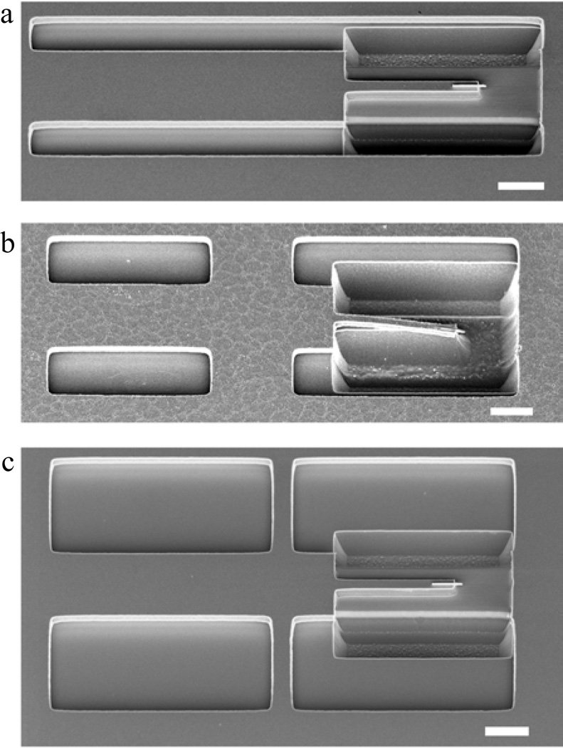
FIG. 5.
SEM images of unsuccessful alternative dimensions for the support tabs, slit widths, and silicon “finger” length. It was observed that (a) no support tabs, (b) long silicon fingers, and (c) wide slits and narrow support tabs all failed to prevent stiction-induced collapse of the leading finger supporting the tip’s overhanging magnet. For comparison, free-standing chips have an observable gap between the finger and the substrate, as shown in Fig. 4(a). All scale bars are 2 µm.

