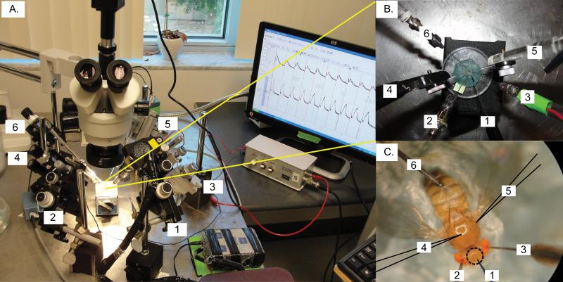
Figure 2. Micromanipulators set-up.
(A)A modified set-up of a previously published protocol14 is used to fit the injection micromanipulator for paired GFS recordings with simultaneous nanoinjections. The mounted fly preparation is oriented with the head of the fly towards the experimenter. The injection micromanipulator (#1) is placed in front of the experimenter between the two manipulators for the tungsten stimulating electrodes (2# and #3). The two micromanipulators for the glass recording electrodes (#4 and #5) are placed on the left and right side, respectively. The micromanipulator for the tungsten ground electrode (#6) is placed furthest in the back either on the left side (shown here) or on the right side.
(B) A close up view from the top of the arrangements of the various electrodes and injection micropipette.
(C) A properly mounted D. melanogaster impaled with electrodes and injection micropipette ready for injection. Notice that the animal's body is mounted with its thorax horizontally and its wings spread out. The wax is securely wrapped around its body preventing the animal from moving. Additionally, the ground electrode (#6, in the abdomen), the glass recording electrodes (#4 and #5, in the thorax, highlighted by dark outlines), and the stimulating electrodes (#2 and #3, one in each eye) are impaled in place, as previously described14. The injection micropipette (#1) is properly aligned with the center of the three ocelli (circled). Insertion of the injection micropipette should be placed in this area.

