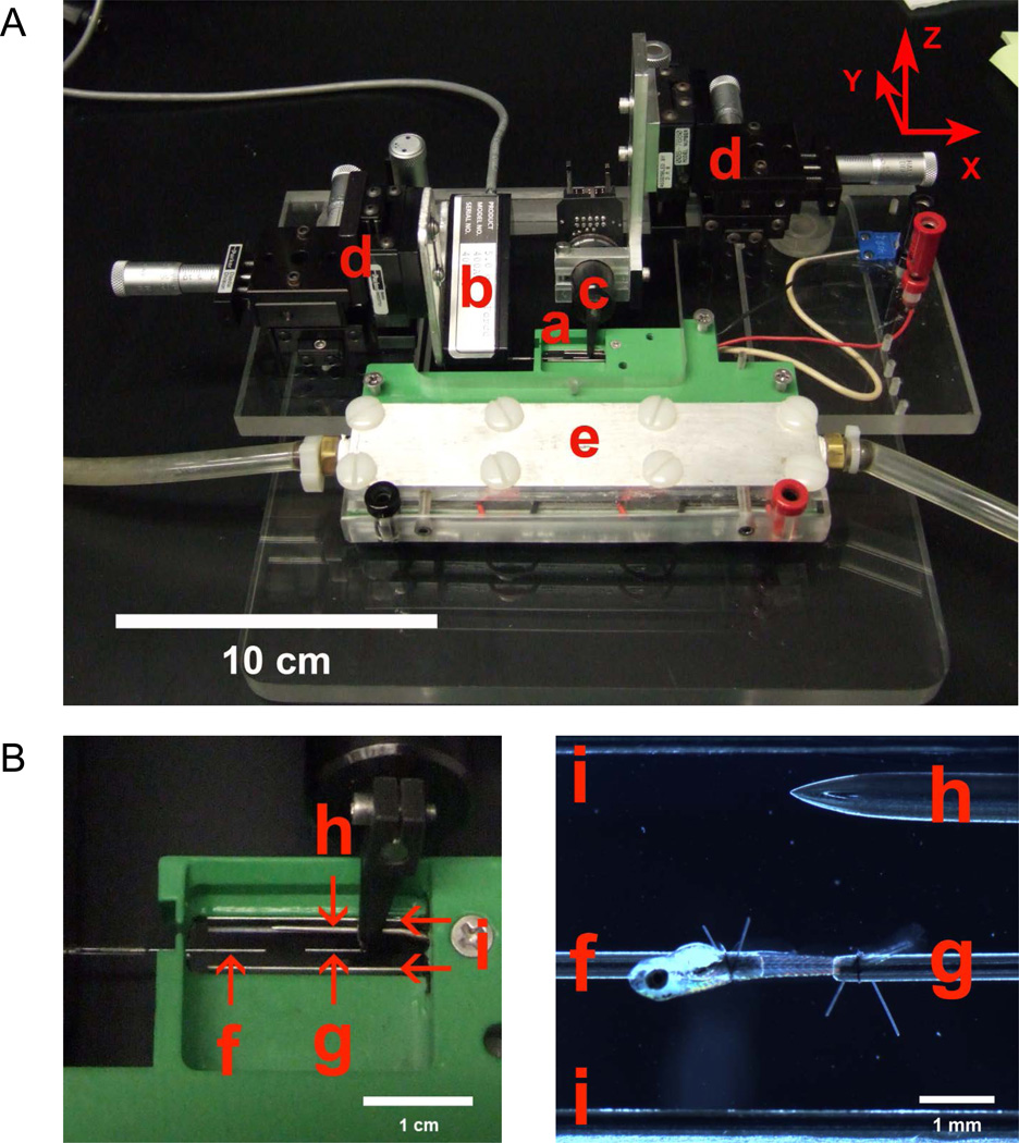
Figure 2.
(A) Testing apparatus with labeled components. (B) Close-up views of the experimental chamber. (a) Experimental chamber with transparent bottom. (b) Force transducer. (c) Length controller. (d) XYZ positioning devices. The X, Y, and Z axes are defined in the upper right corner. (e) Temperature control system utilizing thermoelectric modules. Tubing accommodates water flow for cooling of thermoelectric modules. (f) Stainless steel tube attached to force transducer. (g) Stainless steel tube attached to length controller. (h) Thermometer microprobe. (i) Platinum parallel plate electrodes spanning the length of the chamber. Platinum plates are 2.5 mm high and 0.255 mm thick.

