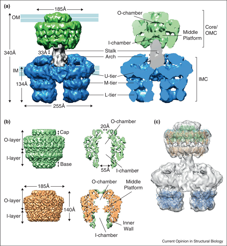
Figure 2.
EM reconstructions showing the structure of the T4SS3–10 complex and the core complex. (a) Front view (left) and cut-away front view (right) of the T4SS3–10 complex (EMD-2567) comprising the core/outer membrane complex (core/OMC, green), the stalk (grey) and the inner membrane complex (IMC, blue). U-tier, M-tier and L-tier stand for upper, middle and lower tier, respectively. The inner (IM) and outer (OM) membranes are indicated. (b) pKM101 core complex (EMD-2232) (top) and truncated core complex lacking the N-terminal part of VirB10 (EMD-2233) (bottom): side view (left) and cut-away side view (right). The bottom right panel shows the superposition of the difference map (between the full-length and the truncated core complex cryo-EM maps) in green, and the cryo-EM structure of the truncated core complex in orange (as in bottom left). The VirB10 N-terminus forms the inner wall of the I-layer and the base. (c) T4SS3–10 complex with fitted crystal structures of the VirB4 C-terminal domain from Thermoanaerobacter pseudethanolicus (PDB: 4AG5) and the pKM101 outer membrane complex (PDB: 3JQO) and in silico model of the N-terminal domain of VirB9 from pKM101 (PDB: 3ZBJ).

