Figure 2.
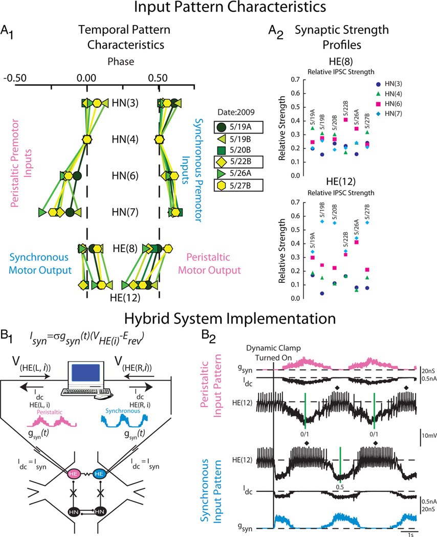
Heart motor neuron ensemble model input pattern characteristics and hybrid system implementation. A1, Simplifiedbilateralphasediagramillustratingthetemporalpatternofthefourpremotor heart interneurons and the HE(8) and HE(12) motor neurons measured in six experimental preparations denoted by the date in 2009 on which the experiments occurred. The letter next to the date denotes the preparation number for that date (A, first; B, second). The line connecting the same colored symbols show the intersegmental phase relationships between the premotor HN interneurons for both the peristaltic and synchronous coordination modes. Motor output is shown opposite its matched premotor input pattern because motor output is out of phase with its premotor input. The color/symbol scheme describing the temporal patterns of the premotor heart interneurons in the different preparations is repeated in Figures 4 and 7 (see key). Preparations 5/19A, 5/22B, and 5/27B were used both in modeling studies as well as in hybrid system experiments (boxes). A2, Synaptic strength profiles of the HE(8) (top) and HE(12) (bottom) heart motor neurons showing the strength of each premotor heart interneuron input, derived from each of the six preparations whose temporal patterns are illustrated in A1. The color code is the same as in Figure 1 (see key). The data for A1 and A2 are adapted from Norris et al. (2011). B1, Hybrid system setup. We recorded simultaneously from a pair of heart (HE) motor neurons [VHE(L,i) and VHE(R,i)] in a given segment, and pharmacologically isolated the motor neurons from their premotor heart (HN) interneuron inputs. The dynamic clamp computes and injects, in real time, the artificial equivalent (Idc) of the appropriate synaptic current (ISyn), into the heart motor neurons according to the equation indicated (see Materials and Methods). One motor neuron received a model derived peristaltic time-varying synaptic conductance wave form[gSyn(t)](pink) and the other motor neuron the synchronous equivalent (light blue). See Materials and Methods for details. B2, Exemplar dynamic-clamp experiment and determination of phase in the hybrid system experiments. At the beginning of the voltage recording, the heart motor neurons were firing tonically; gSyn is 0 nS. The vertical line shows when the dynamic-clamp synapse was activated. The dynamic clamp injects a time-varying current (Idc) proportional to the synaptic conductance gSyn. In subsequent figures, Idc is omitted and only gSyn is shown. The vertical green lines on the peristaltic trace represent the middle spike of our phase reference, the peristaltic HN(4) interneuron. The interval between the two green lines is the cycle period of the phase reference. The vertical green line on the synchronous trace represent the middle spike of the synchronous HN(4) interneuron. In subsequent figures, the middle spike of heart motor neuron bursts are indicated by a filled diamond, and the average phase for an experiment is indicated next to it. The green vertical lines are omitted in subsequent figures.

