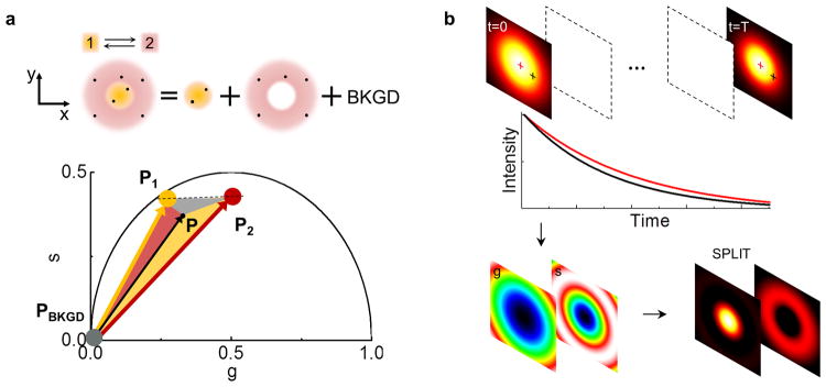
Figure 1. Schematic principle of the SPLIT method.

(a) It is assumed that the photons are emitted within the DL-PSF with a different dynamics (1 or 2) according to the emitter position. The goal is to separate the photons emitted from 1, those emitted from 2 and those with no temporal dynamics (uncorrelated background, BKGD). This is obtained in the phasor plot expressing the experimental phasor P as a linear combination of the phasors P1 and P2 plus the phasor of the background (PBKGD). (b) Schematic of the image formation process in SPLIT. The SPLIT method uses the temporal information of the signal at each pixel to generate a set of g and s images. These images are then processed to obtain the final SPLIT image.
