
Fig. 2.
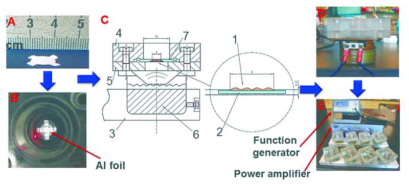
Flowchart showing the bioreactor assembly. (A): A photograph of a four-arm shaped PCL scaffold; (B): A photograph showing the PCL scaffold secured in the vibration chamber and the vibrometer laser focused on the bottom of the chamber; (C): A cross-sectional view of the vibration chamber. 1: PCL scaffold (red); 2: silicone membrane (cyan); 3: Al stationary bar; 4: top acrylic block; 5: bottom acrylic block; 6: mini-woofer; D: side view of the vibration module; E: A photograph showing the entire assembly. This figure has been modified from Tong et al.10 Copyright 2013, Mary Ann Liebert, Inc.