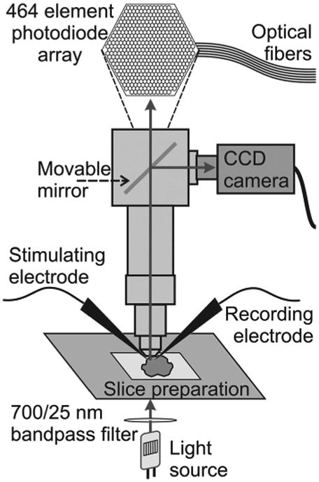
Figure 1.

Experimental setup. Schematic diagram of the microscope, photodiode array, and slice preparation show the basic components of the setup used for imaging experiments. The stimulating and recording electrodes (local field potential recordings) are shown. Arrows indicate the direction of light.
