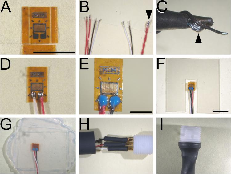
Figure 1. Principal stages of strain gage fabrication.
(A) Dual bonded elements that have been trimmed on three of four sides to final dimensions. (B) Representative ends of wires configured for attachment to gage elements (left) and terminal connectors (right). Note that dual red leads are joined only at the terminal end (arrowhead). (C) Representative placement of a strand of copper wire in proximity to fine (1.5 mm) soldering tip. Maintaining fresh solder along this junction (arrowhead) ensures sufficient heat transfer through the micro tip to melt 63% Tin: 36.65% Lead: 0.35% Antimony solder. (D) Representative extent of solder joints between wire leads and solder pads on the gage element. (E) Properly potted solder joints. (F) Representative notch in the internal silicone laminate sheet to accommodate strain gage element without deforming completed element. (G) Bonded layers of silicone sheets (three in total) forming a completed strain gage prior to final sizing. (H) Wire connections to gold plated sockets are reinforced with layers of succeedingly larger diameter shrink tubing before insertion into electrode pedestal. (I) Final shrink wrap affixing of terminal connectors and electrode pedestal. Calibration bars: (A - D), 5 mm; (E), 2 mm; & (F - I), 5 mm.

