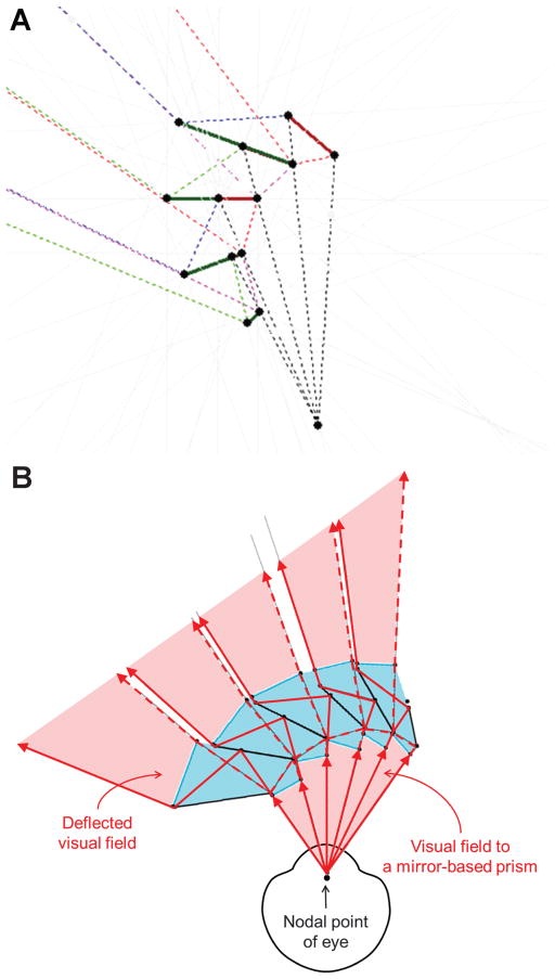
FIGURE 12.
Ray tracing of the field of view constraints of a reflective Fresnel prism design. (A) The mirrors-in-air design is restricted in extent by the limitations imposed by the field of view of each segment (because of lens thickness) and the increased angular rotation of the second prism in every pair, which leads to diminishing size. Shown here for approximately 40 degrees of deflection. The solid lines are mirror segments, and dashed lines are traced rays. (B) A solid design in PMMA provides additional flexibility of design, but with additional complexity. It can result in a larger extent of the Fresnel prism section than the in-air design (A). In the implementation shown here, there are very small blind areas (shown here as white gaps) that, because of their parallel tunnel-field nature,18 result in rapidly diminishing and negligible effects at the distances of objects of interest.

