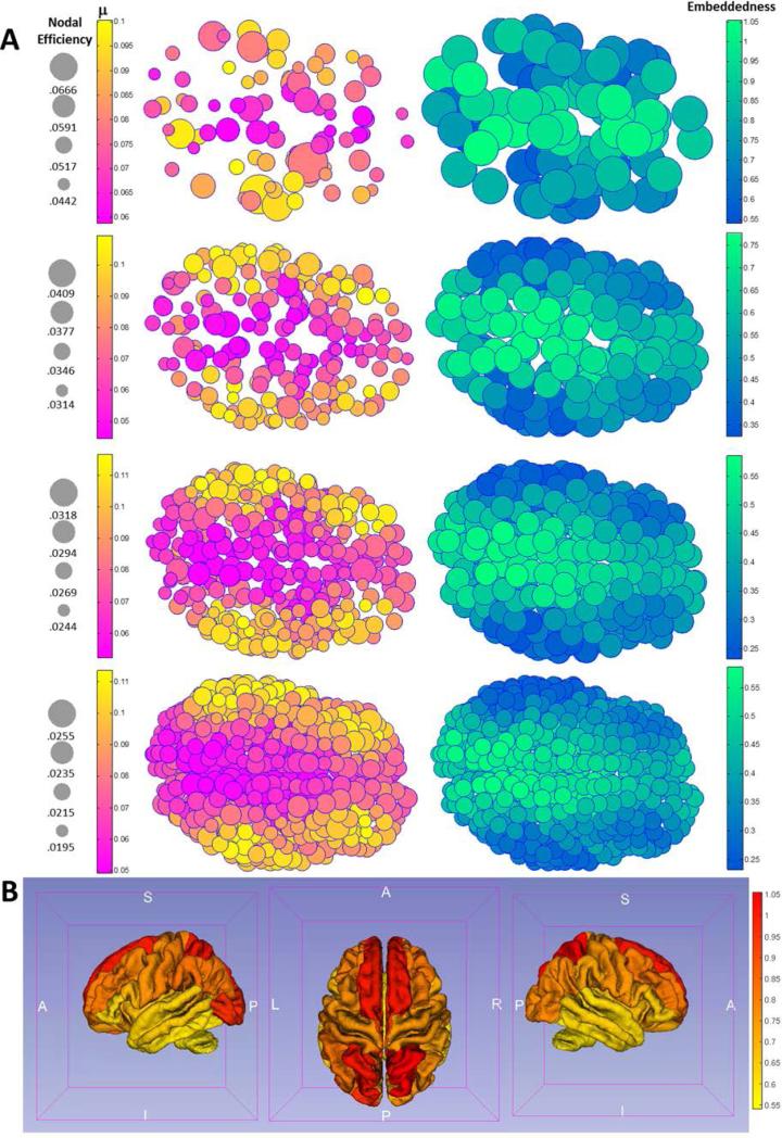
Figure 4.
Figure 4A visualizes both the decay rate constant μi (left panel) and the ratio (right panel) neuroanatomically using top views for all 4 parcellation schemes on the brain surface of a representative subject. Note that visually trends are consistent across all schemes, showing both a posterior-to-anteriro gradient and a medial-to-lateral gradient for μi and (the gradients are increasing for decay rate μi and decreasing for the ratio ). Figure 4B visualizes the embeddedness, as a heat map, on a Freesurfer-defined group average cortical surface using the 82-parcellation scheme.

