
Figure 4.
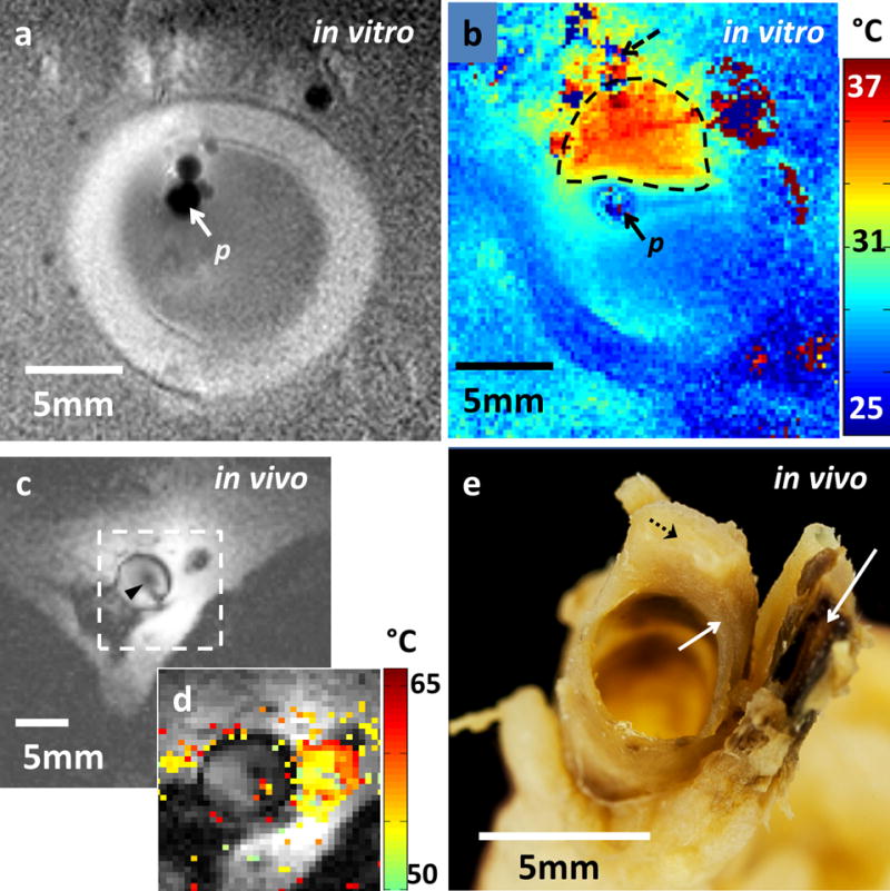
(a) MRI of a porcine aorta acquired in vitro from probe p (3D turbo spin-echo, TSE; TR/TE: 1500/16 ms; voxel-size =0.15×0.15×2 mm3; duration =170 s). (b) Temperature difference image (ΔTe; °C) produced by MRI thermometry (2D GRE; TR/TE =50/25 ms; FA=25°; voxel-size =0.25×0.25×6mm3; duration =8s) relative to a 25°C base-line temperature. The thermally affected region is annotated (dashed area). The artefact in top left (dashed arrow) above the heated area is attributed to rising thermal convection away from the ablation site, causing signal dephasing over the 8s time frame of this scan. (c) MRI acquired with the nitinol-probe (arrowhead) in a rabbit aorta in vivo annotated with a target area (dashed box; MIX sequence, TR/TE =948/22 ms; TI: 300 ms; FA =90°; voxel-size =0.3×0.3×5mm3; duration =240 s). (d) ΔTe map (°C) acquired by MRI thermometry (2D GRE, TR/TE =41/25 ms; FA =24°; voxel-size =0.3×0.3×8mm3; duration =6s) in the target area from (c), overlaid on the MRI. (e) Tissue damage in vessel wall and surroundings evidenced by dark discoloration (arrows) compared to the yellow viable tissue (dashed arrow) in post-mortem photograph of the sectioned vessel.