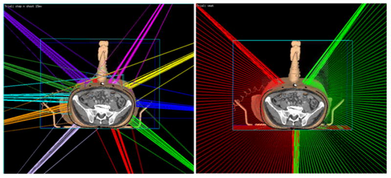
Fig. 8.

The 3D rendering of beam orientations for virtual simulation IMRT plan (left) and VMAT plan (right) of an example patient from this study in our planning system Pinnacle. The step-and-shoot IMRT plan consists of 10 beams, each beam has 5 to10 segments. The VMAT plan is composed of two arcs; each arc has about 70 control points. Gantry angle interval between two consecutive control points is 2 degree. In both IMRT and VMAT plans, the beam is restricted as least 30 degrees away from the probe.
