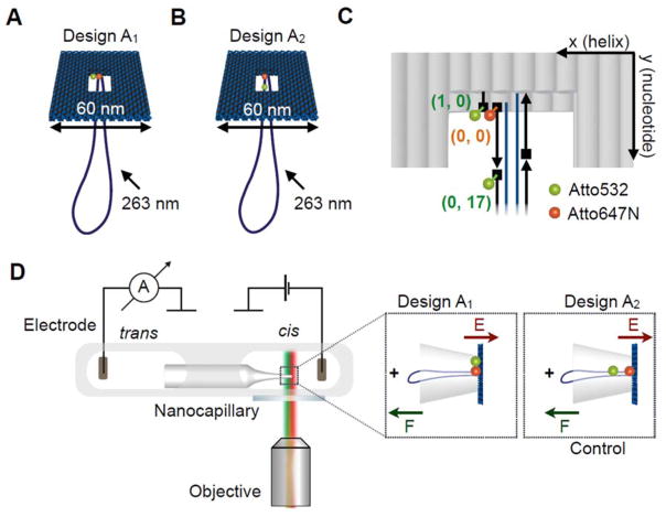
Figure 1.
A Illustration of the DNA origami plate with a double-stranded leash protruding from its central aperture. The plate is labelled with a FRET pair located at the edge of the central opening. The donor dye (ATTO532, green) is located closer to the edge of the plate while the acceptor is close to the leash in the centre (ATTO647N, red). B Illustration of the control DNA origami plate with leash labelled with the same FRET pair. The green donor dye is now located on the leash. C Exact positions of the dyes in the central part of the two-layered DNA origami platform. Each grey rod represents a double helix and the scaffold strand in dark blue and staple strands in black. The ATTO dyes are located in three locations. We denote the positions using a DNA origami coordinate system (x, y) with x (helix number) and y (nucleotide number). The acceptor dye (ATTO647N) is defined as origin (0, 0) and is attached to the 5′-end (illustrated as rectangle) of the staple strand marking the starting point of the leash with respect to the plate. One donor dye (ATTO532) can be positioned at the 5′-end of a staple one helix away (1, 0) at the edge of the plate. Another donor dye (ATTO532) can be positioned at the 5′-end of the staple strand adjacent to the acceptor strand in a distance of 17 nucleotides from the acceptor dye along the leash (0, 17). D Schematic of experimental design. The core of the experimental setup consists of a nanocapillary connecting two electrolyte reservoirs. A voltage can be applied across the nanocapillary for ionic current recordings. The microfluidic chip containing the nanocapillary is placed directly above a fluorescence microscopy objective for synchronous single-molecule fluorescence imaging. (Insets) The DNA origami plate is trapped onto the nanocapillary tip upon applying a positive voltage.

