

Abstract
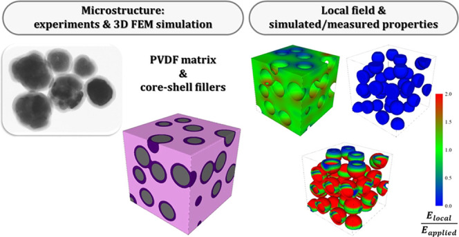
Polymer-based nanocomposites containing inorganic ferroelectric inclusions, typically ABO3 perovskites, have emerged as innovative dielectric materials for energy storage and electric insulation, potentially coupling the high breakdown strength (BDS) and easy processing of polymers with the enhancement of dielectric constant provided by the ferroelectric phase. In this paper, experimental data and three-dimensional finite element method (3D FEM) simulations were combined to shed some light on the effect of microstructures on the dielectric properties of poly(vinylidene fluoride) (PVDF)-BaTiO3 composites. The existence of particle aggregates or touching particles has a strong effect on the effective dielectric constant and determines an increase of the local field in the neck region of the ferroelectric phase with a detrimental effect on the BDS. The distribution of the field and the effective permittivity are very sensitive to the specific microstructure considered. The degradation of the BDS can be overcome by coating the ferroelectric particles with a thin shell of an insulating oxide with a low dielectric constant, such as SiO2 (εr = 4). The local field is highly concentrated on the shell, while the field in the ferroelectric phase is reduced almost to zero and that on the matrix is close to the applied one. The electric field in the matrix becomes less homogeneous with increasing the dielectric constant of the shell material, as happens with TiO2 (εr = 30). These results provide a solid background to explain the enhanced dielectric properties and the superior BDS of composites containing core–shell inclusions.
Keywords: polymer matrix composites, 3D FEM modeling, energy storage, ferroelectrics, electric properties
Introduction
Polymer-based composites containing insulating inorganic fillers are attracting a great deal of interest as potential dielectric materials for high-energy-density capacitors and other applications, including embedded planar capacitors, electroluminescent displays, and insulating layers. They potentially combine typical properties of polymers, such as easy processing at low temperature, flexibility, and high breakdown strength (BDS) with the high relative dielectric constant (or dielectric permittivity, εr′) of some inorganic compounds and, in particular, of ferroelectric perovskites such as BaTiO3, (Ba,Sr)TiO3, and Pb(Zr,Ti)O3. These perovskites have εr′ of the order of 1–5 × 10³ and loss tangent (tan δ) of 0.01–0.02 at room temperature, though their BDS is much lower than that of polymers. Among polymer matrices, poly(vinylidene fluoride) (PVDF) and PVDF-based copolymers are largely investigated because of their relatively high dielectric constant (about 10), low dielectric losses (tan δ = 0.02–0.05), ferroelectric character, and a remarkable BDS of 1500–5000 kV/cm. Since the energy density in a capacitor is proportional to the permittivity of the dielectric, composites with high εr′ are preferred in energy storage applications.1−4 However, the effective permittivity of the composite increases slowly with the volume fraction of inorganic filler, and substantial amounts of ceramic particles are needed to get a permittivity a few times higher than that of PVDF. For example, the addition of 30 vol % BaTiO3 particles leads to values of εr′ in the range 20–40, depending on composite processing, filler synthesis method, surface functionalization of filler particles, as well as on microstructural features such as shape and size of the inclusions.3 In general, an increase of composite BDS can be attained by reducing the particle size to a few tens of nm, provided that a homogeneous dispersion of the fillers is realized.5−7 The shape and orientation of nonspherical particles (sheets and fibers) have a strong effect on dielectric properties.8 Composites containing nanofibers aligned perpendicular to the direction of the applied field (the most common case) show the minimum increase of dielectric response and the maximum improvement of BDS.9 Composites containing a limited amount of BaTiO3 nanofibers (either neat or coated) often show higher permittivity than the materials containing spherical particles, at least for low filler amounts.3 However, the use of spherical fillers is most common and simplifies the material processing.
Surface functionalization of BaTiO3 has been widely investigated as a strategy to enhance the matrix–filler compatibility and, thus, the adhesion of the polymer on the inorganic surface.3,4,10−17 Surface functionalization can facilitate the dispersion of the inclusions in the polymer matrix, leading to a more homogeneous microstructure. While suppression of the loss tangent is generally observed, the effect on the dielectric constant is contrasting.
A further strategy to improve the dielectric properties of PVDF-BaTiO3 composites is by coating the ferroelectric inclusions with a film of a highly insulating binary oxide, such as SiO2,18−20 Al2O3,21−24 TiO2,25−29 and MgO.30 Some common trends have been identified irrespective of the shell nature and filler morphology (equiaxed particles or fibers/wires): the BDS is increased while the losses and leakage current are reduced, resulting in the improvement of the energy charge/discharge efficiency despite a lowering of the dielectric constant is generally observed. Two qualitative explanations have been proposed to elucidate the beneficial effect. First, the highly insulating coating avoids the formation of conducting pathways between percolating inclusions.3,31 Second, the interposition of an additional layer minimizes the electric mismatch between matrix and ferroelectric inclusion (“buffer” layer concept).3,4,14,26,30 However, this latter concept has not been elaborated using quantitative models. In some cases, a relatively high dielectric constant (of the order of 50 for 30 vol % spherical inclusions) is observed, even for coated inclusions.17,26 A reason for the improved dielectric response could be related to the contribution of an additional dielectric relaxation process taking place around room temperature over a wide frequency range.
A further important factor that is neglected in most studies despite its potential impact on the dielectric properties of composites is that the filler particles (either neat or coated) often form aggregates rather than being isolated. Aggregates frequently originate at the synthesis stage and, especially in the case of nanoparticles, are retained in the ensuing composites. Looking at the fracture surface of many composites, the existence of particle aggregates seems quite common.13,16,17,20,22,23,29,32 Furthermore, when the amount of filler is significant (≥30 vol %), approaching the percolation threshold, particles come in contact for merely statistical reasons. Despite the large numbers of studies on polymer-based composites with inorganic fillers, a detailed understanding of the impact of the interparticle contacts and, more generally, of microstructure is still largely missing, while finite element modeling (FEM) usually does not take explicitly into account the existence of aggregates or touching inclusions.16,17,21,25 Cai et al.,33 in their notable article, have concluded, on the basis of 2D FEM simulations, that a nonuniform distribution of ceramic nanoparticles will aggravate the concentration of local electric field, thus slightly enhancing the dielectric response but seriously decreasing the BDS of nanocomposites. However, composites containing touching particles and coated inclusions were not considered, while a comparison with experimental data is missing.
In this paper, we combine 3D FEM calculations and experimental results to gain insight into the effect of particle aggregation and particle coating on the dielectric properties of PVDF-based composites containing spherical BaTiO3 inclusions.
Composites were prepared with neat BaTiO3 (BT) particles, TiO2-coated BaTiO3 (BT@TiO2) particles, and SiO2-coated BaTiO3 (BT@SiO2) particles. The binary oxides have been selected as inorganic coatings because they correspond to two well-distinct situations. While the dielectric constant of TiO2 is intermediate between PVDF and BaTiO3, the permittivity of SiO2 is lower than that of the other two components. Furthermore, both oxides are excellent insulators with a high BDS. The distribution of the electric field in the material and the effective permittivity have been calculated for composites containing 30 vol % inclusions with variable agglomeration degrees, either containing single-phase BT particles or core–shell structures (BT@TiO2 and BT@SiO2), and the results have been compared with the experimental data.
Results and Discussion
Microstructure and Phase Composition
A detailed microstructural characterization was performed on both the inclusions and the composites to evaluate the shell thickness and the filler distribution inside the polymer matrix. Representative images of the morphology of BT@SiO2 and BT@TiO2 particles are shown in Figure 1. The crystal structure of the BT nanoparticles (mean size of 125 nm) is pseudocubic, as indicated by the X-ray diffraction pattern reported in Figure S1. The silica coating is homogeneous with a nearly constant thickness, whereas the titania shell is more irregular. The estimated average shell thickness and relative shell volume are reported in Table 1. The composites are free of evident porosity and show a good dispersion of the inorganic inclusions though the formation of small aggregates is evident. For composites with neat BT and BT@SiO2 fillers, single particles and agglomerates are well visible, as shown on the composite fracture surface of Figure 1. For BT@TiO2 inclusions, only a limited number of isolated particles are observed, and most of the inclusions correspond to agglomerates with a size <1 μm.
Figure 1.

Morphology of (a) BaTiO3@SiO2 and (b) BaTiO3@TiO2 particles. SEM images of the fracture surfaces of (c) C-BT, (d) C-BT-S15, and (e) C-BT-T13 composites. The white circles show the location of some particle agglomerates. Bar: 1 μm.
Table 1. Shell Type, Average Shell Thickness, and Relative Shell Volume of the Different BaTiO3 Particles Used for the Preparation of the Investigated PVDF-Based Composites (Columns 2–4), Dielectric Constant, Loss Tangent, Recoverable Energy Density, and Efficiency of Composites (Columns 5–8).
| composite | shell type | average shell thickness (nm) | volume fraction of shell (%) | dielectric constant at 1 kHz | loss tangent at 1 kHz | recoverable energy storage density (J·cm–3) | efficiency (%) |
|---|---|---|---|---|---|---|---|
| C-BT | 31.8 | 0.030 | 0.287 | 52 | |||
| C-BT-T6 | TiO2 | 6 | 24.0 | 20.9 | 0.023 | 0.213 | 62 |
| C-BT-T13 | 13 | 43.0 | 19.0 | 0.020 | 0.142 | 55 | |
| C-BT-T22 | 22 | 59.5 | 18.0 | 0.023 | 0.125 | 55 | |
| C-BT-S6 | SiO2 | 5.5 | 22.4 | 17.8 | 0.020 | 0.129 | 38 |
| C-BT-S15 | 15 | 47.5 | 13.9 | 0.024 | 0.098 | 41 |
According to the DSC measurements, the crystalline fraction in the polymer matrix is close to 50% in most samples and increases to ≈60% in composites with the BT@SiO2 inclusions (Table 2). The ATR-FTIR spectra (see Figure S2) indicate that the PVDF matrix contains only the polymorphs α and β with a predominance (up to 68%) of the latter phase in most composites (Table 2). The introduction of ceramic fillers significantly increases the fraction of ferroelectric β phase in comparison to the neat polymer, as already reported.34 The particles with the TiO2 shell seem especially effective, in agreement with previous work on composites with titania fillers.35
Table 2. Crystalline Fraction of PVDF (Xc), Amount of β Phase Referred to the Crystalline Fraction (Fβ) and to Overall Polymer Amount (FEA) for the Neat PVDF Polymer, and the PVDF-Based Composite Films.
| composite | Xc (%) | Fβ (%) | FEA (%) |
|---|---|---|---|
| PVDF polymer | 54 | 40 | 22 |
| C-BT | 50 | 57 | 27 |
| C-BT-T6 | 51 | 60 | 31 |
| C-BT-T13 | 49 | 64 | 31 |
| C-BT-T22 | 49 | 68 | 33 |
| C-BT-S6 | 61 | 53 | 32 |
| C-BT-S15 | 59 | 48 | 28 |
Low-Field Dielectric Properties
The low-field dielectric properties of C-BT-Ty composites are shown in Figure 2. The titania coating determines a systematic drop of permittivity with the shell thickness, from 32 (uncoated inclusions) to 21 (C-BT-T6), 19 (C-BT-T13), and 18 (C-BT-T22), respectively, at 1 kHz. For comparison sake, the permittivity of PVDF thick films processed with the same procedure is 10 at 1 kHz.36 The incorporation of coated particles does not determine an anomalous increase of permittivity at low frequency as observed in some composites and probably attributable to extrinsic interfacial polarization processes.16,17,37
Figure 2.

Room-temperature dielectric properties of PVDF composites containing 30 vol % of BT-Ty inclusions. (a) Relative dielectric constant. (b) Loss tangent. The data of composite C-BT are reported for comparison.
The presence of the TiO2 shell leads to a reduction of the dielectric losses to <0.03 in the range 102–104 Hz, the same level observed in the neat polymer.38 The loss tangent is increased at lower frequencies yet comparable to PVDF. Similar trends are also exhibited by composites containing the BaTiO3@SiO2 inclusions (Figure 3), though the permittivity undergoes a larger decrease. At 1 kHz, ε′ is 18 for C-BT-S6 and 14 for C-BT-S15. Irrespective of the coating nature, even a relatively thin shell of 6 nm (24% of the inclusion volume) is enough to suppress the dielectric constant by 34% (TiO2 shell) and 44% (SiO2 shell).
Figure 3.

Room-temperature dielectric properties of PVDF composites containing 30 vol % of BT-Sy inclusions. (a) Relative dielectric constant. (b) Loss tangent. The data of composite C-BT are reported for comparison.
High-Field Properties
The dielectric displacement vs field amplitude loops for the different composites measured at 10 Hz under a maximum field amplitude of 460 kV/cm are reported in Figure 4. In this field range, the nanocomposite materials behave as linear dielectrics with small losses. The maximum applied field is much lower than the coercive field of PVDF, and thus the dissipative motion and reorientation of the domains responsible for the polarization switching are not activated yet. Nevertheless, a significant impact of the filler coating can be observed. For all composites containing the core–shell particles, the loop area and, consequently, the losses are smaller than those of the material prepared using the uncoated particles. This indicates that the coating, either with TiO2 or SiO2, enhances the insulating properties of the composites, even at relatively high fields. Because of the lower losses, the C-BT-Ty composites have higher efficiency in energy storage (Table 1), although the energy density is inferior. The slant of the P(E) loops (Figure 4) decreases with increasing the shell thickness. This is a consequence of the diminishing effective permittivity, as the dielectric constant is proportional to the first derivative of the dielectric displacement with respect to the field.
Figure 4.

Dielectric displacement vs electric field loops at 10 Hz. (a) Composites with BaTiO3@TiO2 particles. (b) Composites with BaTiO3@SiO2 particles. The data of composite C-BT are reported for comparison.
FEM Simulations
Some selected results of FEM simulations for composites containing uncoated BT particles are shown in Figure 5. The figure reports the normalized local field (Elocal/Eapplied) distribution in the BT phase of four distinct microstructures selected from a number of simulations. It is worth remembering that the microstructures were randomly generated each time. The first one (Figure 5a), corresponding to perfectly isolated particles, gives the lowest permittivity value of 24.5. For noninteracting inclusions, the effective permittivity is practically independent on the specific configuration considered. All three other microstructures, containing a different number of contact points located in different positions, give higher εeff values, up to 44.2. The existence of interparticle contacts has a substantial effect on the effective permittivity, which increases considerably in comparison to the ideal case of perfectly isolated particles. The average value resulting from several calculations is ≈32, close to the experimental result (Table 1). In the absence of contact points, the electric field in the BT inclusions is practically suppressed by the presence of the low permittivity matrix, which tends to concentrate in its volume the field lines (i.e., the lower permittivity dielectric is subjected to a higher field). The distribution of the electric field in the matrix is highly inhomogeneous irrespective of the existence of interparticle contacts. As an example, the distribution of the electric field in the matrix and BT inclusions for the composite with εeff = 32.68 is shown Figure 6. As discussed in a previous paper,39 the increase of εeff in ideal composites with respect to the pure polymer is related only to the enhancement of the local field in the polymer matrix and not to the contribution of the high-permittivity component to the total energy of the system. However, when some particles touch each other, the electric field in the contact region increases considerably and can get similar (green regions) or even higher (yellow and red regions in Figures 5c and 6c) values than the applied field. The enhancement of the local field in BT provides an additional contribution to the effective dielectric constant of the composite and points out the significant effect exerted by the existence of agglomerates or touching particles, i.e., by the microstructure. As shown in Figure 5, the electric field distribution in the inclusions is much broader than in the ideal case of isolated particles. In particular, the local field is maximized when the segment connecting the centers of the two interacting particles is perpendicular to the applied field (see the red region for case (c) in Figure 5). Consequently, the field on the filler can exceed the BDS of BT (100–150 kV/cm40,41), even when the applied field is far from the critical threshold. The local failure can then trigger the propagation of a fatal crack. The risk of local failure is less serious for the matrix because the BDS of PVDF is usually 1–2 orders of magnitude (1500–5000 kV/cm3) higher than that of the inclusions.
Figure 5.

Local electric field maps and distributions in BT phase (30 vol %) as determined by FEM simulations in four PVDF-BT composites with different microstructures: perfectly isolated particles and εeff = 24.5 (a), touching particles and εeff = 29.4 (b), touching particles and εeff = 44.2 (c). The microstructure and local field maps for the composite with εeff = 32.7 are shown in Figure 6.
Figure 6.

Microstructure of a (a) PVDF-BT composite containing 30 vol % BT particles with εeff = 32.7 and local field maps in (b) PVDF matrix and (c) BT inclusions simulated by FEM.
The presence of the SiO2 shell (εr′ = 4) on the BT particles leads to a completely different electric field distribution (Figure 7). Even for touching inclusions, the electric field on the BT phase is virtually zero. The electric field on the matrix is relatively homogeneous and close to the applied field. In contrast, the field in the silica shell is highly inhomogeneous and strongly enhanced in comparison to the applied field, as apparent from the very broad local field distribution, which extends to values up to 6–7 times the applied field. Despite this strong increase of the local field, the BDS of silica is very high (5–15 × 103 kV/cm42), and thus the composite can withstand very high applied fields. The BDS of PVDF composites with silica-coated BT inclusions is reported to be significantly larger than that of PVDF.20 Thus, the effect of the silica coating is to protect both the BT filler and the polymer matrix from breakdown. A further consequence of the homogeneous fields on both the BT particles and the matrix is that εeff is only weakly dependent on the specific microstructure. The main drawback of using a silica coating is the resulting lower effective permittivity of such composites, which is predicted to be 12.3 for isolated inclusions and 12.8 for touching particles for a shell thickness of 15 nm, values not far from the experimental result of 13.9. A strongly suppressed permittivity results in a drop of the energy storage density (Table 1). However, these drawbacks can be partly relieved using thinner coatings. The simulations indicate that when the shell thickness is 5 nm, the effective permittivity increases to ≈18.
Figure 7.

(a) Microstructure of a PVDF composite with BaTiO3@SiO2 inclusions (30 vol %), (b) local field distribution expressed on a number of elements basis and the local field maps (c) in the BT inclusions, (d) polymer matrix, and (e) silica shell, simulated by FEM. Shell thickness is 15 nm.
The effect of TiO2 coating is summarized in Figure 8 for a shell thickness of 15 nm. Again, the coating leads to zeroing the electric field in the BT phase, but now, the local field is enhanced on both the shell and matrix and is strongly inhomogeneous. In particular, the field on the titania phase is maximized at the contact points. The value of εeff is 20.4 for isolated inclusions and 21.06 for touching particles, while the experimental result is 19 for a shell thickness of 13 nm. Similarly to the effect of the SiO2 shell, a titania coating protects both the BaTiO3 particles and the PVDF matrix from breakdown28,29 with the advantage of a higher effective permittivity, which is twice that of the neat polymer. Consequently, a gain of a factor of about 2 for the discharged energy density can be expected for a loss-free composite in comparison to PVDF for the same applied field. The BDS of rutile is 800 kV/cm,42 but no data are available for amorphous TiO2. Composites containing 30 vol % of BaTiO3@TiO2 particles have a BDS of 3700–3800 kV/cm28,29 comparable with that of composites with BaTiO3@SiO2 inclusions,20 and this supports a rather high breakdown voltage also for amorphous titania.
Figure 8.

(a) Microstructure of a PVDF composite with BaTiO3@TiO2 inclusions (30 vol %), (b) local field distribution expressed on a number of elements basis and the local field maps in (c) the BT inclusions, (d) polymer matrix, and (e) titania shell, simulated by FEM. Shell thickness is 15 nm.
The different behavior of the silica-coated and titania-coated inclusions is mainly determined by the dielectric constant of the shell. The dielectric constant of SiO2 is less than the permittivity of both PVDF and BaTiO3. Consequently, only the shell experiences high field values much larger than the applied field.
The above results identify 3D FEM simulations as a valuable tool for the design of dielectric composites with better properties. The calculation presented here can be extended to filler particles with different shapes and sizes and to explore architectures with improved dielectric response such as inclusions decorated with smaller particles of high permittivity, inclusions with multiple shells, star-like particles (and more generally particles with many spikes), and particles with high aspect ratio with embedded high-permittivity inclusions. In particular, fibers and sheets containing dispersed BaTiO3 nanoparticles have shown enhanced dielectric properties and BDS;21,23,43 similar architectures would deserve further FEM investigations. However, comparison of the FEM simulations with experimental results remains a fundamental step to gain further insight into processing–microstructure–property relationships of composite materials.
Conclusions
In this paper, we have combined experimental data and 3D FEM simulations to shed some light on the role of microstructure on the dielectric properties of PVDF-BaTiO3 composites, with special attention to the effect of a thin shell of an oxide such as SiO2 or TiO2 on the perovskite surface. The main conclusions are as follows:
In ideal composites with randomly distributed and well-isolated high-permittivity particles, the local field on the inclusions is virtually zero, while a strongly inhomogeneous and locally enhanced field (Elocal > Eapplied) acts on the matrix. This is a consequence of the much higher permittivity of the inclusions (εr′ ≈ 103) in comparison to the polymer (εr′ = 10). The increase of the effective permittivity with respect to the neat polymer value is only determined by the enhancement of the local field in the PVDF matrix and not by the contribution of the high-permittivity component to the total energy of the system.
The presence of particle agglomerates and touching particles results in an increase of the local field in the contact region of the high-permittivity inclusions. Elocal is highly dependent on the orientation of the contact point with respect to the applied field and is even larger than Eapplied. Therefore, εeff increases in comparison to the equivalent composite containing isolated particles owing to the additional contribution to the total electrostatic energy of the system determined by the enhancement of the field in the high-permittivity phase. However, the local field at the contact points can exceed the relatively low BDS (≈100 kV/cm) of the high-permittivity ferroelectric phase determining a deterioration of the breakdown strength of the composite.
The use of core–shell inclusions provides an effective approach to overcome the degradation of the BDS in composites containing particle agglomerates because the local field in the contact region of the high-permittivity phase is again reduced to zero. The same consideration applies to percolating composites. When the permittivity of the shell is less than that of the polymer (the case of SiO2), the field in the matrix will be close to the applied field. Thus, the BDS of the composite will be largely determined by the breakdown resistance of the shell, whose composition should be carefully selected to sustain local fields several times larger than the applied field. When the permittivity of the shell is intermediate between that of the matrix and that of the core (the case of TiO2), an inhomogeneous distribution of the field with local enhancements will again take place in the matrix, but the field in the core is still zeroed. Even for isolated particles, the use of a shell with low permittivity will enhance the BDS by lowering the local field in the matrix. Core–shell inclusions represent an effective approach to resolve the paradox that composites with a high dielectric constant usually suffer from the low breakdown strength of the high-permittivity ferroelectric fillers, high dielectric losses, and high leakage currents. The main disadvantage is represented by the drop of permittivity, which decreases with increasing shell thickness. The use of very thin coatings can limit this problem.
The above considerations apply to high-quality composites without porosity and good adhesion of the polymer matrix to the filler particles. Functionalization of the inclusions can be an effective solution to increase the polymer–filler compatibility. The contribution of additional dielectric relaxation phenomena associated with interfacial polarization or determined by a specific polymer coating can increase the effective permittivity of composites beyond the values predicted by the present FEM models.
The 3D FEM simulations represent a valuable tool for the design of dielectric composites with better properties.
Methods
Preparation of Filler Particles
A commercial poly(vinylidene fluoride) (PVDF) grade provided by Solvay (Solef 1008) was employed as a polymer matrix for the preparation of the composites. In the following, some of its relevant characteristics are itemized: Mn = 114 × 103 g/mol and Mw = 244 × 103 g/mol, MFI@230 °C = 24 g/10 min (ASTM D1238, 5 kg), melting point 172 °C.44
BaTiO3 (BT) nanoparticles with an average diameter of 125 nm were synthesized with a hydrothermal-like method using BaCl2·2H2O (Aldrich, 99.9%) and TiCl4 (Aldrich, 99.9%) precursors as described in.45 The BT particles were used as such or coated with a silica (SiO2) or titania (TiO2) shell. BT@TiO2 inclusions were prepared by a two-step method previously used for coating different kinds of inorganic particles.46 First, the BT particles were suspended in a peroxotitanium(IV) solution at pH 9 prepared from TiCl4 (Aldrich, 99.9%). Subsequently, the hydrolysis of the peroxotitanium(IV) complex induced by heating the solution for 4 h at 95 °C determined the formation of an amorphous titania coating on the BT particles. The thickness of the shell was controlled by the titanium concentration in the suspension. The obtained titania-coated particles are denoted as BT-Ty in the following, where T stands for TiO2 and y is the shell thickness (in nm).
The silica-coated particles (BT@SiO2) were prepared according to the modified Stöber-like process described by Mornet et al.47 In a typical synthesis, 0.5 g of BaTiO3 was dispersed by ultrasonication in 10 mL of nitric acid solution (1 M) and then in citric acid solution (0.01 M) and then washed with distilled water. Afterward, 200 μL of an ammonia solution (25 wt %) was added to a particle dispersion in distilled water. The obtained suspension was poured in a mixture of H2O/EtOH/NH3 (75/23.5/1.5 vol %) and reacted with a proper amount of tetraethyl orthosilicate (TEOS) solution (0.1 M in ethanol), added by dripping with a Hamilton syringe pump. The thickness of the shell was controlled by the amount of added solution.
The obtained silica-coated particles are denoted as BT-Sy in the following, where S stands for SiO2 and y is the shell thickness (in nm). In both cases, the average thickness of the shell was determined from TEM images of the coated particles.
Preparation of Composites
Composites containing 30 vol % of BT, BT@TiO2, and BT@SiO2 particles were prepared by solvent casting. The particles were dispersed in dimethylacetamide (DMA) by overnight mixing using YSZ media, and the final suspension was added to a solution of PVDF in DMA (20 wt %). The mixture was stirred at 90 °C until evaporation of most of the solvent and then poured on a glass substrate. The resultant film was finally dried in a vacuum and then in a vented oven; complete DMA removal was verified by attenuated total reflectance (ATR)-Fourier transform infrared (FTIR) spectroscopy. The obtained composites were compression-molded using a semiautomatic press P200E (Collin GmbH) using a two-step process previously optimized to obtain a high amount of ferroelectric β PVDF polymorph.36 In this procedure, a 3 mm thick plate of the composite is prepared at 200 °C and 50 bar for 4 min and then repressed at 170 °C and 240 bar for 4 min to obtain final sheets 0.6–0.8 mm thick. The composites were denoted with the same name of the corresponding filler particles inserting the prefix “C-.”
Microstructural and Dielectric Characterization
Morphological analyses of the particles and the fragile fractured composite surfaces were carried out using a Hitachi TM3000 benchtop SEM microscope (15 kV) and, for higher magnification, an LEO 1450VP (LEO Electron Microscopy Ltd.) SEM microscope (20 kV). A Zeiss EM900 TEM microscope (80 kV) was also employed to study the inclusions morphology and determine the thickness of the binary oxide shell.
A FTIR spectrometer (PerkinElmer Spectrum Two) operating in ATR mode was used to characterize neat PVDF, ceramic particles, and their composites. The quantitative evaluation of the relative fraction, FEA, of the crystalline electroactive phase (β and/or γ) in the PVDF matrix was carried out as previously described, using the infrared spectra.36 The crystallinity degree (Xc) of neat PVDF and of the composite materials was estimated with differential scanning calorimetry (DSC) using a Mettler DSC 821e instrument and considering the method reported in ref (36).
For dielectric characterization, the sample surfaces were sputtered with Au–Pd to obtain circular electrodes (diameter: 2.4 cm), and frequency sweep measurements (1 Hz to 1 MHz) at room temperature were performed using a Solartron SI1260 frequency response analyzer with a Novocontrol BDC dielectric interface. The relative dielectric constant (real part of permittivity, εr′) and tan δ (ratio of imaginary to real part of permittivity, εr″/εr′) were recorded.
Polarization vs field P(E) measurements were carried out at room temperature on electrode samples immersed in a transformer oil bath by a Sawyer–Tower modified circuit fed by a high-voltage sinewave (frequency: 10 Hz, maximum field amplitude: 460 kV/cm) using a TREK amplifier.
Finite Element Modeling
The composites were simulated by a 3D approach, assuming a random distribution of spherical particles (30 vol %) in a polymer matrix. Three types of spherical inclusions were considered: neat BaTiO3, BaTiO3@SiO2, and BaTiO3@TiO2. The diameter of the BaTiO3 particles was 125 nm (corresponding to the average size experimentally determined), and the thickness of the shell was varied between 5 and 20 nm, corresponding to a shell volume fraction from 20.6 to 56.8%.
According to our previous experimental data36 recorded on polymer films processed with the same procedure, a value εr′(PVDF) = 10 was assumed as representative of the relative dielectric constant of the PVDF matrix. The dielectric constant of the BaTiO3 particles was considered equal to 1000, a reasonable value for particles of this size, in agreement with recent measurements, εr′ = 1150, for 100 nm particles.48 Indeed, the permittivity of barium titanate is strongly dependent on size,49 but considering that εr′(BaTiO3) is much larger than that of the other phases, the exact value of the dielectric constant of barium titanate is practically irrelevant and determines only minor variations of the composite permittivity. Indeed, the BaTiO3 particles are subjected to very low local field values, and the increase of the effective permittivity is predominantly caused by the enhancement of the local fields located on the lower permittivity phases. A relative dielectric constant εr′(SiO2) = 4 was assumed for silica, in agreement with the literature data of fused silica and silica-rich glasses.42 Although polycrystalline rutile TiO2 has εr′ ≈ 100,42 amorphous titania has a lower permittivity, and values between 15 and 50 have been reported for thin films grown in different conditions.50−53 In the present calculations, it was assumed εr′(TiO2) = 30. To avoid any confusion, the dielectric constant of the composites, as obtained from FEM calculations, is denoted by εeff.
The microstructures of the composites (i.e., the way the spherical particles are arranged in the polymer matrix) have been randomly generated by considering a minimum distance of 130 or 120 nm between the inclusions’ centers to obtain either perfectly isolated particles or partially clustered inclusions, respectively. Cubic volumes of 1 μm3 having various types of fillers, as described before, were numerically generated and further divided into 27 million meshing elements. Further, the Laplace equation was solved using a Galerkin procedure described elsewhere,54 considering boundary conditions in a plan parallel-plate capacitor configuration with electrodes located on the top and bottom surfaces, subjected to a voltage of 1 V. This numerical procedure allows the calculation of the local potentials and electric fields and the determination of the effective permittivity from the total energy of the whole capacitor computed as a sum of electrostatic energy values of all of the discrete elements.
Acknowledgments
Part of this research work was supported by the Bank Foundation Compagnia di San Paolo, Torino, Italy [Project “Polycom: Engineered polymeric composites with high energy density” (ID ROL: 10359)]. The support of Romanian Ministry of Education and Research, CNCS–UEFISCDI, Project Number PN-III-P1-1.1-TE-2019-1929 within PNCDI III is acknowledged. The support of the Short Term Mobility program of the CNR “PVDF-based composites effect of surface engineering on energy density” is acknowledged.
Supporting Information Available
The Supporting Information is available free of charge at https://pubs.acs.org/doi/10.1021/acsami.2c23013.
X-ray diffraction patterns of the BaTiO3 and BaTiO3@TiO2 powders and ATR-FTIR spectra of the neat PVDF and the composite films (PDF)
The authors declare no competing financial interest.
Supplementary Material
References
- Srivastava S.; Schaefer J. L.; Yang Z.; Tu Z.; Archer L. A. Polymer–Particle Composites: Phase Stability and Applications in Electrochemical Energy Storage. Adv. Mater. 2014, 26, 201–234. 10.1002/adma.201303070. [DOI] [PubMed] [Google Scholar]
- Dang Z.-M.; Yuan J.-K.; Zha J.-W.; Zhou T.; Li S.-T.; Hu G.-H. Fundamentals, Processes and Applications of High-Permittivity Polymer–Matrix Composites. Prog. Mater. Sci. 2012, 57, 660–723. 10.1016/j.pmatsci.2011.08.001. [DOI] [Google Scholar]
- Prateek; Thakur V. K.; Gupta R. K. Recent Progress on Ferroelectric Polymer-Based Nanocomposites for High Energy Density Capacitors: Synthesis, Dielectric Properties, and Future Aspects. Chem. Rev. 2016, 116, 4260–4317. 10.1021/acs.chemrev.5b00495. [DOI] [PubMed] [Google Scholar]
- Huang X.; Jiang P. Core–Shell Structured High-k Polymer Nanocomposites for Energy Storage and Dielectric Applications. Adv. Mater. 2015, 27, 546–554. 10.1002/adma.201401310. [DOI] [PubMed] [Google Scholar]
- Hao Y.; Wang X.; Bi K.; Zhang J.; Huang Y.; Wu L.; Zhao P.; Xu K.; Lei M.; Li L. Significantly Enhanced Energy Storage Performance Promoted by Ultimate Sized Ferroelectric BaTiO3 Fillers in Nanocomposite Films. Nano Energy 2017, 31, 49–56. 10.1016/j.nanoen.2016.11.008. [DOI] [Google Scholar]
- Bi M.; Hao Y.; Zhang J.; Lei M.; Bi K. Particle Size Effect of BaTiO3 Nanofillers on the Energy Storage Performance of Polymer Nanocomposites. Nanoscale 2017, 9, 16386. 10.1039/C7NR05212J. [DOI] [PubMed] [Google Scholar]
- Zazoum B. Evaluation and Optimization of Dielectric Properties of PVDF/BaTiO3 Nanocomposites Film for Energy Storage and Sensors. ECS J. Solid State Sci. Technol. 2020, 9, 115005 10.1149/2162-8777/aba1fe. [DOI] [Google Scholar]
- Huang X.; Sun B.; Zhu Y.; Li S.; Jiang P. High-k Polymer Nanocomposites with 1D Filler for Dielectric and Energy Storage Applications. Prog. Mater. Sci. 2019, 100, 187–225. 10.1016/j.pmatsci.2018.10.003. [DOI] [Google Scholar]
- Cai Z.; Wang X.; Luo B.; Hong W.; Wu L.; Li L. Nanocomposites with Enhanced Dielectric Permittivity and Breakdown Strength by Microstructure Design of Nanofillers. Compos. Sci. Technol. 2017, 151, 109–114. 10.1016/j.compscitech.2017.08.015. [DOI] [Google Scholar]
- Dang Z.-M.; Wang H.-Y.; Xu H.-P. Influence of Silane coupling agent on morphology and dielectric property in BaTiO3/polyvinylidene fluoride composites. Appl. Phys. Lett. 2006, 89, 112902 10.1063/1.2338529. [DOI] [Google Scholar]
- Li J.; Claude J.; Norena-Franco L. E.; Seok S. I.; Wang Q. Electrical Energy Storage in Ferroelectric Polymer Nanocomposites Containing Surface-Functionalized BaTiO3 Nanoparticles. Chem. Mater. 2008, 20, 6304–6306. 10.1021/cm8021648. [DOI] [Google Scholar]
- Li J.; Seok S. I.; Chu B.; Dogan F.; Zhang Q.; Wang Q. Nanocomposites of Ferroelectric Polymers with TiO2 Nanoparticles Exhibiting Significantly Enhanced Electrical Energy Density. Adv. Mater. 2009, 21, 217–221. 10.1002/adma.200801106. [DOI] [Google Scholar]
- Kim P.; Doss N. M.; Tillotson J. P.; Hotchkiss P. J.; Pan M.-J.; Marder S. R.; Li J.; Calame J. P.; Perry J. W. High Energy Density Nanocomposites Based on Surface-Modified BaTiO3 and a Ferroelectric Polymer. ACS Nano 2009, 3, 2581–2592. 10.1021/nn9006412. [DOI] [PubMed] [Google Scholar]
- Zhou T.; Zha J.-W.; Cui R.-Y.; Fan B.-H.; Yuan J.-K.; Dang Z.-M. Improving Dielectric Properties of BaTiO3/Ferroelectric Polymer Composites by Employing Surface Hydroxylated BaTiO3 Nanoparticles. ACS Appl. Mater. Interfaces 2011, 3, 2184–2188. 10.1021/am200492q. [DOI] [PubMed] [Google Scholar]
- Xie L.; Huang X.; Wu C.; Jiang P. Core-Shell Structured Poly(methyl methacrylate)/BaTiO3 Nanocomposites Prepared by in Situ Atom Transfer Radical Polymerization: a Route to High Dielectric Constant Materials with the Inherent Low Loss of the Base Polymer. J. Mater. Chem. 2011, 21, 5897–5906. 10.1039/c0jm04574h. [DOI] [Google Scholar]
- Zhu M.; Huang X.; Yang K.; Zhai X.; Zhang J.; He J.; Jiang P. Energy Storage in Ferroelectric Polymer Nanocomposites Filled with Core–Shell Structured Polymer@BaTiO3 Nanoparticles: Understanding the Role of Polymer Shells in the Interfacial Regions. ACS Appl. Mater. Interfaces 2014, 6, 19644–19654. 10.1021/am504428u. [DOI] [PubMed] [Google Scholar]
- Fu J.; Hou Y.; Zheng M.; Wei Q.; Zhu M.; Yan H. Improving Dielectric Properties of PVDF Composites by Employing Surface Modified Strong Polarized BaTiO3 Particles Derived by Molten Salt Method. ACS Appl. Mater. Interfaces 2015, 7, 24480–24491. 10.1021/acsami.5b05344. [DOI] [PubMed] [Google Scholar]
- Yu K.; Niu Y.; Bai Y.; Zhou Y.; Wang H. Poly(vinylidene fluoride) Polymer Based Nanocomposites with Significantly Reduced Energy Loss by Filling with Core-Shell Structured BaTiO3/SiO2 Nanoparticles. Appl. Phys. Lett. 2013, 102, 102903 10.1063/1.4795017. [DOI] [Google Scholar]
- Liu S.; Xue S.; Shen B.; Zhai J. Reduced Energy Loss in Poly(vinylidene fluoride) Nanocomposites by Filling with a Small Loading of Core-Shell Structured BaTiO3/SiO2 Nanofibers. Appl. Phys. Lett. 2015, 107, 032907 10.1063/1.4927330. [DOI] [Google Scholar]
- Bi K.; Bi M.; Hao Y.; Luo W.; Cai Z.; Wang X.; Huang Y. Ultrafine Core-Shell BaTiO3@SiO2 Structures for Nanocomposite Capacitors with High Energy Density. Nano Energy 2018, 51, 513–523. 10.1016/j.nanoen.2018.07.006. [DOI] [Google Scholar]
- Pan Z.; Yao L.; Zhai J.; Shen B.; Liu S.; Wang H.; Liu J. Excellent Energy Density of Polymer Nanocomposites Containing BaTiO3@Al2O3 Nanofibers Induced by Moderate Interfacial Area. J. Mater. Chem. A 2016, 4, 13259–13264. 10.1039/C6TA05233A. [DOI] [Google Scholar]
- He D.; Wang Y.; Chen X.; Deng Y. Core–Shell Structured BaTiO3@Al2O3 Nanoparticles in Polymer Composites for Dielectric Loss Suppression and Breakdown Strength Enhancement. Composites, Part A 2017, 93, 137–143. 10.1016/j.compositesa.2016.11.025. [DOI] [Google Scholar]
- Yao M.; You S.; Peng Y. Dielectric Constant and Energy Density of Poly(vinylidene fluoride) Nanocomposites Flled with Core-Shell Structured BaTiO3@Al2O3 Nanoparticles. Ceram. Int. 2017, 43, 3127–3132. 10.1016/j.ceramint.2016.11.128. [DOI] [Google Scholar]
- Liu S.; Wang J.; Shen B.; Zhai J.; Hao H.; Zhao L. Poly(vinylidene fluoride) Nanocomposites with a Small Loading of Core-Shell Structured BaTiO3@Al2O3 Nanofibers Exhibiting High Discharged Energy Density and Efficiency. J. Alloys Compd. 2017, 696, 136–142. 10.1016/j.jallcom.2016.11.186. [DOI] [Google Scholar]
- Pan Z.; Yao L.; Zhai J.; Fu D.; Shen B.; Wang H. High-Energy-Density Polymer Nanocomposites Composed of Newly Structured One-Dimensional BaTiO3@Al2O3 Nanofibers. ACS Appl. Mater. Interfaces 2017, 9, 4024–4033. 10.1021/acsami.6b13663. [DOI] [PubMed] [Google Scholar]
- Rahimabady M.; Mirshekarloo M. S.; Yao K.; Lu L. Dielectric Behaviors and High Energy Storage Density of Nanocomposites with Core–Shell BaTiO3@TiO2 in Poly(vinylidene fluoride-hexafluoropropylene). Phys. Chem. Chem. Phys. 2013, 15, 16242–16248. 10.1039/c3cp52267a. [DOI] [PubMed] [Google Scholar]
- Zhang X.; Shen Y.; Zhang Q.; Gu L.; Hu Y.; Du J.; Lin Y.; Nan C.-W. Ultrahigh Energy Density of Polymer Nanocomposites Containing BaTiO3@TiO2 Nanofibers by Atomic-Scale Interface Engineering. Adv. Mater. 2015, 27, 819–824. 10.1002/adma.201404101. [DOI] [PubMed] [Google Scholar]
- Lin X.; Hu P.; Jia Z.; Gao S. Enhanced Electric Displacement Induces Large Energy Density in Polymer Nanocomposites Containing Core–Shell Structured BaTiO3@TiO2 Nanofibers. J. Mater. Chem. A 2016, 4, 2314–2320. 10.1039/C5TA09547F. [DOI] [Google Scholar]
- Hu P.; Jia Z.; Shen Z.; Wang P.; Liu X. High Dielectric Constant and Energy Density Induced By The Tunable Tio2 Interfacial Buffer Layer In Pvdf Nanocomposite Contained With Core–Shell Structured Tio2@Batio3 Nanoparticles. Appl. Surf. Sci. 2018, 441, 824–831. 10.1016/j.apsusc.2018.02.112. [DOI] [Google Scholar]
- Wang P.-J.; Zhou D.; Guo H.-H.; Liu W.-F.; Su J.-Z.; Fu M.-S.; Singh C.; Trukhanov S.; Trukhanov A. Ultrahigh Enhancement Rate of the Energy density of Flexible Polymer Nanocomposites using Core–Shell BaTiO3@MgO Structures as the Filler. J. Mater. Chem. A 2020, 8, 11124. 10.1039/D0TA03304A. [DOI] [Google Scholar]
- Jian G.; Liu M.; Yan C.; Wu F.; Son B.; Moon K.-S.; Wong C.-P. A Strategy For Design Of Non-Percolative Composites With Stable Giant Dielectric Constants and High Energy Densities. Nano Energy 2019, 58, 419–426. 10.1016/j.nanoen.2019.01.037. [DOI] [Google Scholar]
- Dang Z.-M.; Wang H.-Y.; Zhang Y.-H.; Qi J.-Q. Morphology and Dielectric Property of Homogenous BaTiO3/PVDF Nanocomposites Prepared via the Natural Adsorption Action of Nanosized BaTiO3. Macromol. Rapid Commun. 2005, 26, 1185–1189. 10.1002/marc.200500137. [DOI] [Google Scholar]
- Cai Z.; Wang X.; Luo B.; Hong W.; Wu L.; Li L. Dielectric Response and Breakdown Behavior of Polymer-Ceramic Nanocomposites: The Effect of Nanoparticle Distribution. Compos. Sci. Technol. 2017, 145, 105–113. 10.1016/j.compscitech.2017.03.039. [DOI] [Google Scholar]
- Gebrekrstos A.; Muzata T. S.; Ray S. S. Nanoparticle-Enhanced β-Phase Formation in Electroactive PVDF Composites: A Review of Systems for Applications in Energy Harvesting, EMI Shielding, and Membrane Technology. ACS Appl. Nano Mater. 2022, 5, 7632–7651. 10.1021/acsanm.2c02183. [DOI] [Google Scholar]
- Alam M. M.; Sultana A.; Sarkar D.; Mandal D. Electroactive β-crystalline Phase Inclusion and Photoluminescence Response of a Heat-controlled Spin-Coated PVDF/TiO2 Free-Standing Nanocomposite Film for a Nanogenerator and an Active Nanosensor. Nanotechnology 2017, 28, 365401 10.1088/1361-6528/aa7b25. [DOI] [PubMed] [Google Scholar]
- Brunengo E.; Castellano M.; Conzatti L.; Canu G.; Buscaglia V.; Stagnaro P. PVDF-based Composites Containing PZT Particles: How Processing Affects the Final Properties. J. Appl. Polym. Sci. 2020, 137, 48871. 10.1002/app.48871. [DOI] [Google Scholar]
- Xie L.; Huang X.; Huang Y.; Yang K.; Jiang P. Core-shell Structured Hyperbranched Aromatic Polyamide/BaTiO3 Hybrid Filler for Poly(vinylidene fluoride-trifluoroethylenechlorofluoroethylene) Nanocomposites with the Dielectric Constant Comparable to That of Percolative Composites. ACS Appl. Mater. Interfaces 2013, 5, 1747–1756. 10.1021/am302959n. [DOI] [PubMed] [Google Scholar]
- Brunengo E.; Conzatti L.; Schizzi I.; Buscaglia M. T.; Canu G.; Curecheriu L.; Costa C.; Castellano M.; Mitoseriu L.; Stagnaro P.; Buscaglia V. Improved Dielectric Properties of Poly(vinylidene fluoride)–BaTiO3 Composites by Solvent-Free Processing. J. Appl. Polym. Sci. 2021, 138, 50049. 10.1002/app.50049. [DOI] [Google Scholar]
- Padurariu L.; Curecheriu L. P.; Mitoseriu L. Nonlinear Dielectric Properties of Paraelectric-Dielectric Composites Described by a 3D Finite Element Method Based on Landau-Devonshire Theory. Acta Mater. 2016, 103, 724–734. 10.1016/j.actamat.2015.11.008. [DOI] [Google Scholar]
- Schomann K. D. Electric Breakdown of Barium Titanate: a Model. Appl. Phys. 1975, 6, 89–92. 10.1007/BF00883554. [DOI] [Google Scholar]
- Buscaglia V.; Buscaglia M. T.; Canu G.. BaTiO3-Based Ceramics: Fundamentals, Properties and Applications. In Encyclopedia of Materials: Technical Ceramics and Glasses; Elsevier, 2021; Vol. 3, pp 311–344. [Google Scholar]
- Kingery W.; Bowen H.; Uhlmann D.. Introduction to Ceramics; John Wiley and Sons, 1960; pp 947–963. [Google Scholar]
- Jian G.; Jiao Y.; Feng L.; Meng Q.; Yang N.; Zhu S.; Lü M.; Wong C.-P. High energy Density of BaTiO3@TiO2 Nanosheet/Polymer Composites via Ping-Pong-Like Electron Area Scattering and Interface Engineering. NPG Asia Mater. 2022, 14, 4. 10.1038/s41427-022-00356-w. [DOI] [Google Scholar]
- Solvay . SOLEF 1008 Data Sheet, 2008. https://www.solvay.com/en/product/solef-10080001.
- Testino A.; Buscaglia M. T.; Buscaglia V.; Viviani M.; Bottino C.; Nanni P. Kinetics and Mechanism of Aqueous Chemical Synthesis of BaTiO3 Particles. Chem. Mater. 2004, 16, 1536. 10.1021/cm031130k. [DOI] [Google Scholar]
- Airimioaei M.; Buscaglia M. T.; Tredici I.; Anselmi-Tamburini U.; Ciomaga C. E.; Curecheriu L.; Bencan A.; Buscaglia V.; Mitoseriu L. SrTiO3–BaTiO3 Nanocomposites with Temperature Independent Permittivity and Linear Tunability Fabricated Using Field-Assisted Sintering from Chemically Synthesized Powders. J. Mater. Chem. C 2017, 5, 9028. 10.1039/C7TC02629C. [DOI] [Google Scholar]
- Mornet S.; Elissalde C.; Hornebecq V.; Bidault O.; Duguet E.; Brisson A.; Maglione M. Controlled Growth of Silica Shell on Ba0.6Sr0.4TiO3 Nanoparticles Used as Precursors of Ferroelectric Composites. Chem. Mater. 2005, 17, 4530–4536. 10.1021/cm050884r. [DOI] [Google Scholar]
- Cooper E.; De Anda E.; Flitz E.; Kim H.; Casañas N.; Johnson L.; Kedzierski Z.; Domrzalski J.; Dato A.; Monson T. Investigating the Dielectric Constant of Barium Titanate in a Polymer-Matrix Nanocomposite. MRS Adv. 2022, 7, 799–804. 10.1557/s43580-022-00319-x. [DOI] [Google Scholar]
- Buscaglia V.; Randall C. A. Size and Scaling Effects in Barium Titanate. An Overview. J. Eur. Ceram. Soc. 2020, 40, 3744–3758. 10.1016/j.jeurceramsoc.2020.01.021. [DOI] [Google Scholar]
- Ha H.-K.; Yoshimoto M.; Koinuma H.; et al. Open Air Plasma Chemical Vapor Deposition of Highly Dielectric Amorphous TiO2 films. Appl. Phys. Lett. 1996, 68, 2965. 10.1063/1.116370. [DOI] [Google Scholar]
- Cheng Q.; Ahmad W.; Liu G.; Wang K. In Structural Evolution of Amorphous Thin Films of Titanium Dioxide, 11th IEEE International Conference on Nanotechnology, Portland, OR, August 15–18, 2011.
- Busani T.; Devine R. A. B. Dielectric and Infrared Properties of TiO2 Films Containing anatase and Rutile. Semicond. Sci. Technol. 2005, 20, 870–875. 10.1088/0268-1242/20/8/043. [DOI] [Google Scholar]
- Elbahri M. B.; Kahouli A.; Mercey B.; Prellier W.; Lüders U. Effects of Oxygen Pressure During Deposition on the Dielectric Properties of Amorphous Titanium Dioxide Thin Films. J. Phys. D: Appl. Phys. 2019, 52, 175308 10.1088/1361-6463/ab06a1. [DOI] [Google Scholar]
- Guzu A.; Ciomaga C. E.; Airimioaei M.; Padurariu L.; Curecheriu L. P.; Dumitru I.; Gheorghiu F.; Stoian G.; Grigoras M.; Lupu N.; Asandulesa M.; Mitoseriu L. Functional Properties of Randomly Mixed and Layered BaTiO3 - CoFe2O4 Ceramic Composites Close to the Percolation Limit. J. Alloys Compd. 2019, 796, 55–64. 10.1016/j.jallcom.2019.05.068. [DOI] [Google Scholar]
Associated Data
This section collects any data citations, data availability statements, or supplementary materials included in this article.