Abstract
Alzheimer’s disease (AD) is a brain disorder that eventually causes memory loss and the ability to perform simple cognitive functions; research efforts within pharmaceuticals and other medical treatments have minimal impact on the disease. Our preliminary biological studies showed that Repeated Electromagnetic Field Stimulation (REFMS) applying an EM frequency of 64 MHz and a specific absorption rate (SAR) of 0.4 – 0.9 W/kg decrease the level of amyloid-β peptides (Aβ), which is the most likely etiology of AD. This study emphasizes uniform E/H field and SAR distribution with adequate penetration depth penetration through multiple human head layers driven with low input power for safety treatments. In this work, we performed numerical modeling and computer simulations of a portable Meander Line antenna (MLA) to achieve the required EMF parameters to treat AD. The MLA device features a low cost, small size, wide bandwidth, and the ability to integrate into a portable system. This study utilized a High-Frequency Simulation System (HFSS) in the design of the MLA with the desired characteristics suited for AD treatment in humans. The team designed a 24-turn antenna with a 60 cm length and 25 cm width and achieved the required resonant frequency of 64 MHz. Here we used two numerical human head phantoms to test the antenna, the MIDA and spherical head phantom with six and seven tissue layers, respectively. The antenna was fed from a 50-Watt input source to obtain the SAR of 0.6 W/kg requirement in the center of the simulated brain tissue layer. We found that the E/H field and SAR distribution produced was not homogeneous; there were areas of high SAR values close to the antenna transmitter, also areas of low SAR value far away from the antenna. This paper details the antenna parameters, the scattering parameters response, the efficiency response, and the E and H field distribution; we presented the computer simulation results and discussed future work for a practical model.
Keywords: Alzheimer’s Disease, Meander Line Antenna, HFSS, EMF Linearity, SAR, Field Distribution
1. Introduction
Small size antennas have been the focus of cellular communication systems, bioinstrumentations, medical and IoT devices. This is due to high demand of the compact equipment. The small size antennas in medical applications are suited for use in and around human bodies. There are multiple antenna approaches [1] [2] [3] [4] for the E/H linearity within the human body, while lacks the portable size feature that enables integrating them around the human tissue sizes. The rapid development in devices that emit Radio Frequency Electromagnetic Fields (RF-EMF) has sparked a growing interest in their interaction with biological systems and their beneficial effects on human health. As a result, investigations are motivated by the potential for therapeutic applications and concern for any possible side effects of these EM energies. Some studies have indicated that a specific tuning of experimental and clinical Radio Frequency (RF) exposure may lead to their clinical application toward beneficial health outcomes.
Figure 1 shows the block diagram of the proposed system. The function generator will provide the EM power required to transmit the appropriate SAR in the brain layer. The antenna will radiate and focus the EM energy in the human head phantom direction. The antenna position will be on top of the head phantom. The head phantom will simulate a real human head with 5 tissue layers, EMF exposure will reach a SAR of 0.4 – 0.9 W/kg in the brain layer.
Figure 1.
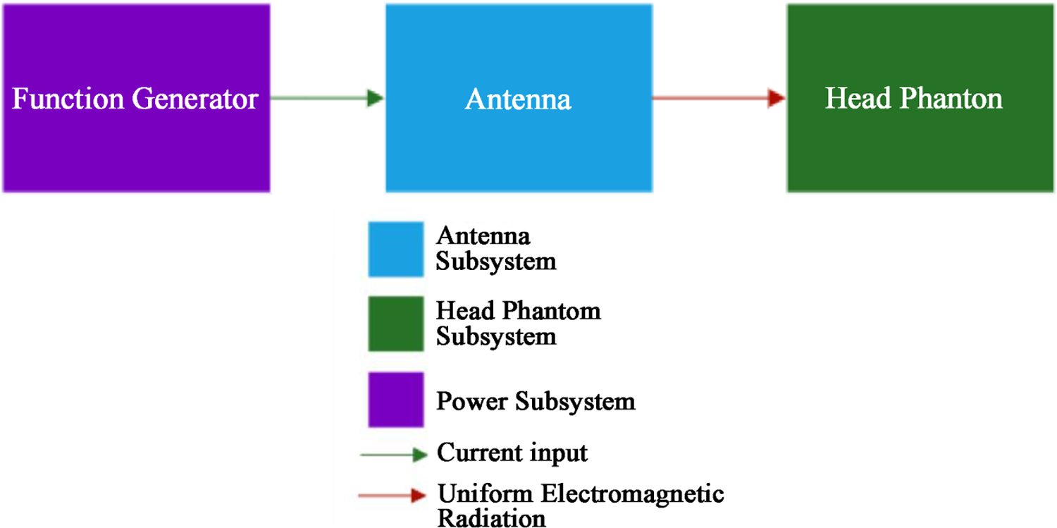
System block diagram.
The application investigated here is the near zone field distribution for HF/VHF antenna since the human head is placed very close to the antenna surface. The study of near zone field has been investigated and measured for their linear distribution [5] [6]. The size of the antenna to perform at 64 MHZ (VHF) is important for wearable devices. The design has been implemented for 64 MHZ while the size of the antenna was beyond the wearing device limitation [7].
2. Antenna Design
We chose the Meander Line Antenna (MLA) for this design [8] [9], because the antenna size is suitable for a portable system and satisfies the AD treatment SAR requirements. Figure 2 shows the geometry, and Table 1 shows the detailed dimensions of the antenna.
Figure 2.
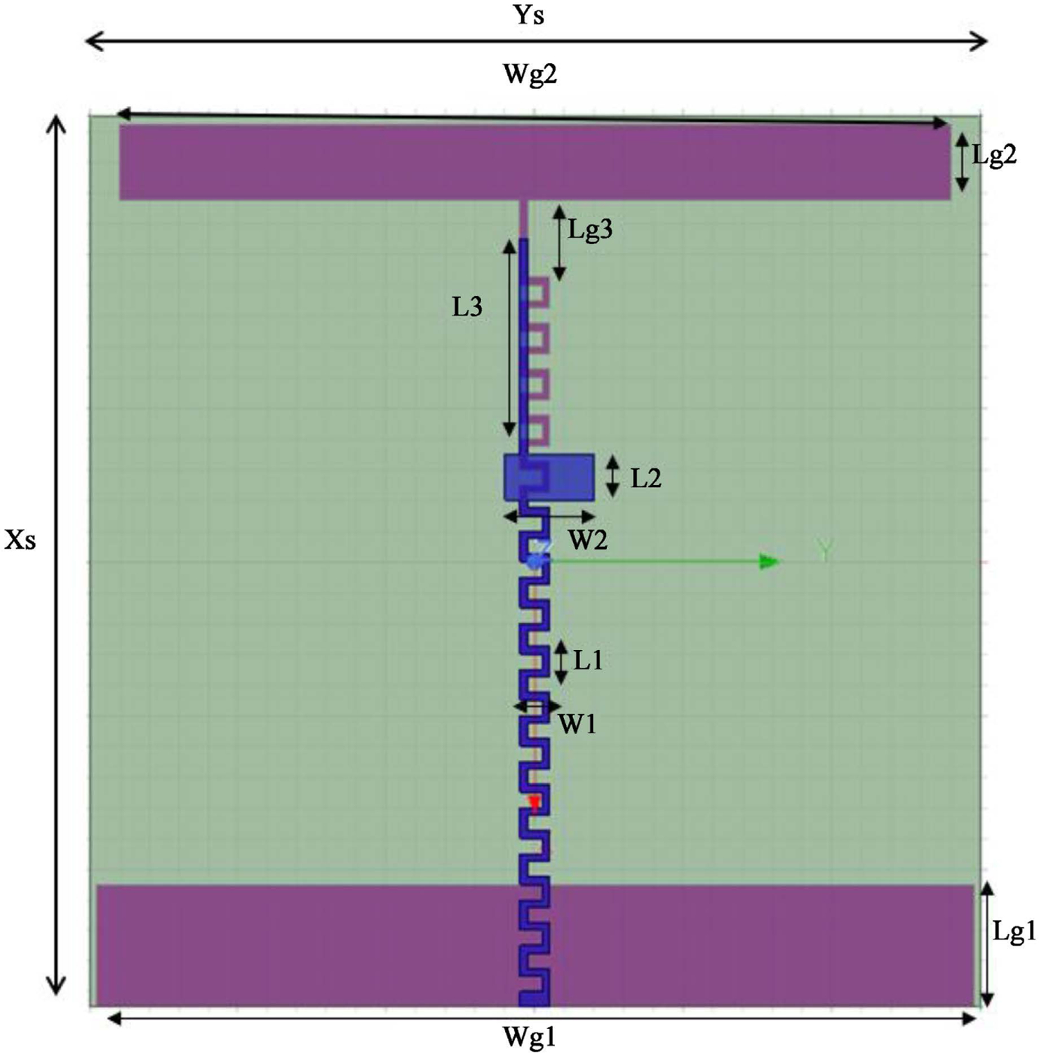
Geometry of the meander monopole line antenna.
Table 1.
Dimensions of the meander monopole line antenna.
| Xs | 58.0 cm | Wg2 | 56.0 cm | L2 | 3.0 cm |
| Ys | 60.0 cm | Lg2 | 5.0 cm | W2 | 6.0 cm |
| Wg1 | 59.0 cm | L1 | 2.0 cm | L3 | 14.0 cm |
| Lg1 | 8.0 cm | W1 | 2.0 cm | Lg3 | 7.0 cm |
Table 2 shows the dimensions of the various layers within the human head phantom and the dielectric properties of each layer. The parameters in Table 2 were incorporated into the HFSS simulation system for the antenna radiation at the given frequency. The material of the substrate is Rogers RO30130 which has a high dielectric value of 10.2 that allows the antenna to obtain a higher gain within the human head phantom direction. The number of meander turns also affects the radiation frequency. The number of turns for the meander line of ground is 27 turns and 21 turns for the top patch.
Table 2.
Properties of the Seven Different Layers of the Brain at a frequency of 64 MHz.
| Layer | Radius (mm) | Permittivity (er) | Permeability | Conductivity (S/m) | Mass Density (kg/m3) |
|---|---|---|---|---|---|
| Skin | 51.0 | 32 | 1 | 0.1483 | 1109.0 |
| Fat | 49.0 | 9 | 1 | 0.0776 | 0911.0 |
| Muscle | 47.0 | 50 | 1 | 0.4466 | 1090.4 |
| Skull | 45.0 | 10 | 1 | 0.0179 | 1908.0 |
| Dura | 36.5 | 40 | 1 | 0.0600 | 1174.0 |
| CSF | 36.0 | 65 | 1 | 1.8790 | 1007.0 |
| Brain | 28.1 | 40 | 1 | 0.6165 | 1045.5 |
3. The Head Phantom Models
In this study, we performed two different simulation head phantom models, the Multimodal Imaging-Based Detailed Anatomical Model of the Human Head and Neck (MIDA), and the Spherical Model Head Phantom.
Both head phantoms were based on the parameters stated in Table 2.
4. Results and Discussion
4.1. Antenna and MIDA Head Phantom
Figure 3 shows the Scattering S11 parameters of the resonating frequency of 64 MHz, and Figure 4 shows the SAR distribution in the MIDA human head phantom. Table 3 shows the minimum and maximum SAR observed in the various layers before reaching the brain layer; the SAR in the brain layer in blue color was between 0.9 and 0.0024 W/kg. We observed that the nonlinearity was an issue with this antenna exposure on the human head phantom model.
Figure 3.
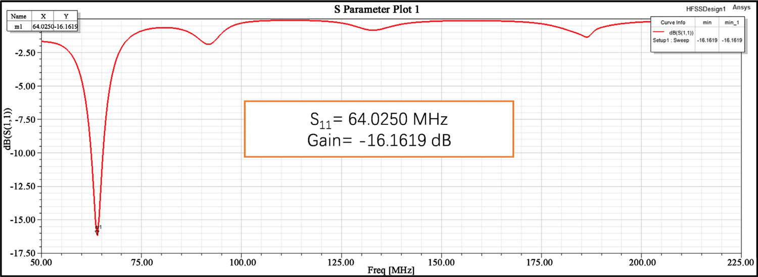
S11 Parameter VS gain graph of the antenna.
Figure 4.
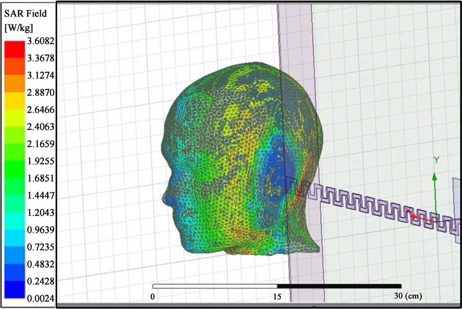
SAR result on the MIDA human head phantom.
Table 3.
Tabulated data of average SAR in the different layers of the MIDA human head phantom.
| Layers | Max. Value of Average SAR (W/kg) | Min. Value of Average SAR (W/kg) |
|---|---|---|
| Skin | 3.6082 | 0.0264 |
| Skull | 2.8870 | 0.0261 |
| Dura | 1.2043 | 0.0104 |
| CSF | 2.1669 | 0.0303 |
| Brain | 0.9639 | 0.0024 |
Within the five different layers of surfaces simulated for the SAR values for the MIDA [10] head phantom, the skin appeared to have a very high average SAR value because it is the closest surface to the antenna radiation. We observed that the power was dissipated in the skin before the radiation reached the skull. The values of the SAR across the head phantom are relatively not linear. One possible cause is that the source of the EMF radiation is on top of the head and the SAR decreases with increasing distance from the antenna. The other cause is that the SAR is calculated based on the mass density of each layer and not on the whole head. This causes some errors in the SAR value and produces a non-homogeneous distribution of the SAR values in each layer. For example, the SAR values in the brain layer are between 0.0024 and 0.9639 W/kg, therefore showing areas of the brain with insufficient energy to produce biological effects. The inconsistency of the SAR values is also due to the complex structure of the MIDA head phantom with complex boundaries between layers.
4.2. Antenna and Spherical Model Head Phantom
We utilized the same MLA antenna to perform EMF exposures to the spherical model head phantom with the S11 parameters. We tried several power levels until we reached the appropriate SAR of 0.4 – 0.9 W/kg. Figure 5 gives the SAR distribution for two different power values; 1 W and 50 W. Table 4 shows the SAR versus power generated and fed into the antenna. We reached a SAR of 0.6 W/kg at the brain tissue of the human head phantom using a power of 50 W.
Figure 5.
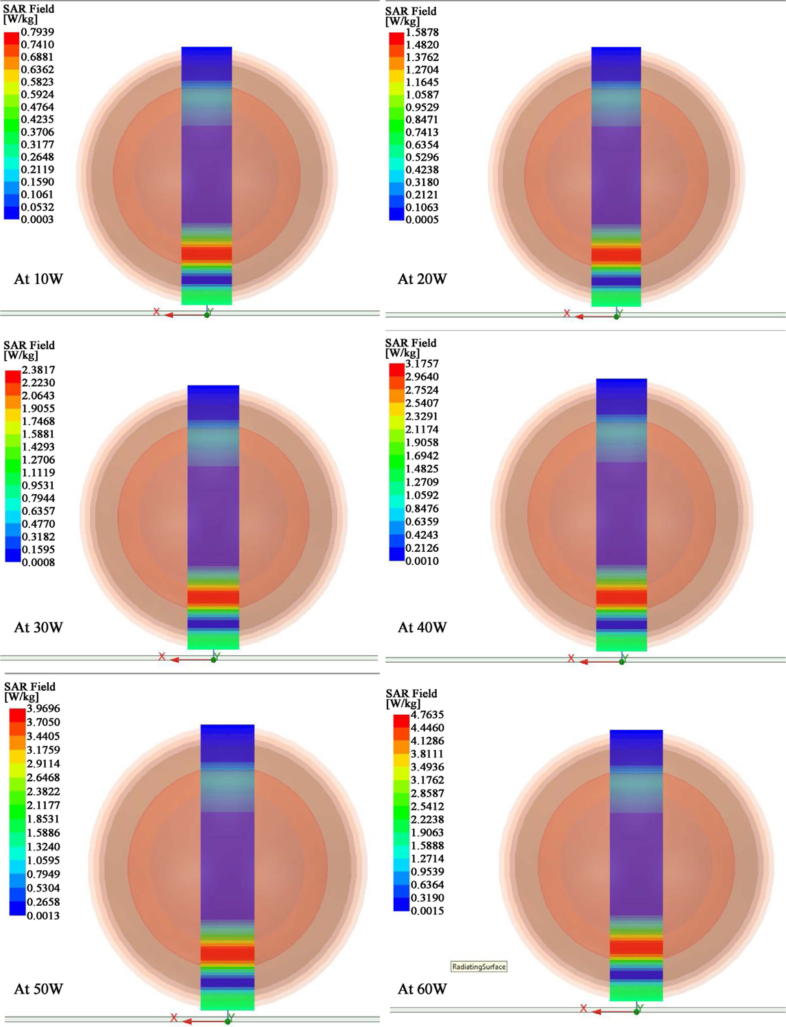
SAR field with various power applied. We determined that the 30 W, 40 W, 50 W and 60 W produced a SAR between 0.4 and 0.9 W/kg (see Table 4) in the center of the simulated brain layer (in purple color).
Table 4.
Average SAR in the simulated brain layer. We increased the power to 50 W to reach a SAR of 0.63 – 0.95 W/kg in the simulated brain.
| Power (W) | Average SAR (W/kg) | Median Value (W/kg) |
|---|---|---|
| 1 | 0.0113 – 0.0170 | 0.01415 |
| 10 | 0.1061 – 0.1590 | 0.13255 |
| 20 | 0.2121 – 0.3180 | 0.26505 |
| 30 | 0.3182 – 0.4770 | 0.39760 |
| 40 | 0.4243 – 0.6359 | 0.53010 |
| 50 | 0.5304 – 0.7929 | 0.66165 |
| 60 | 0.6364 – 0.9539 | 0.79515 |
| 70 | 0.7425 – 1.1129 | 0.9277 |
| 80 | 0.8486 – 1.2719 | 1.06025 |
| 90 | 0.9437 – 1.4309 | 1.1873 |
| 100 | 1.0607 – 1.5898 | 1.32525 |
The average SAR is higher in the layers near the antenna and decreases as the distance increases. These results were expected as the tissues absorbed the energy of the radiation emitted by the antenna. When the power of the antenna is manipulated, we can observe that the distribution pattern of the average SAR is kept constant on each layer of the tissue.
5. Conclusion & Future Work
In this work, we have demonstrated that the MLA antennas are suitable for portable devices and for producing a SAR of 0.4 – 0.9 W/kg in the simulated human brain within reasonable dimensions. The study was based on a near-field distribution. The HFSS simulation showed a scattering parameter S11 at 64 MHZ while keeping the antenna size within the portable range. The two head phantom models studied here show that the spherical model gives accurate data and better linearity; this is caused by the complex mathematical model of the MIDA phantom and the software capacity to handle it. Here we also determined that the SAR values decreased in tissues farthest from the antenna transmitter and produced a non-homogeneous distribution pattern which is not appropriate for future AD treatments unless we use two or more antennas to obtain a more homogeneous SAR distribution. A practical model is needed to confirm the HFSS data model, we will reserve the practical model for future consideration [11] [12].
Acknowledgements
The authors offer their appreciation to the senior design administrators and to Ms. Seemein Shayesteh, the instructor of the senior design course, for their follow-up with this work during the 2022 academic year.
Footnotes
Conflicts of Interest
The authors declare no conflicts of interest regarding the publication of this paper.
References
- [1].Dytioco Santos JP, Fereidoony F, Hedayati M and Wang YE (2020) High Efficiency Bandwidth VHF Electrically Small Antennas through Direct Antenna Modulation. IEEE Transactions on Microwave Theory and Techniques, 68, 5029–5041, 10.1109/TMTT.2020.3016381 [DOI] [Google Scholar]
- [2].Rodriguez V (2018) On Selecting the Most Suitable Range for Antenna Measurements in the VHF-UHF Range. 2018 IEEE Conference on Antenna Measurements & Applications (CAMA), Sweden, 3–6 September 2018, 1–3. 10.1109/CAMA.2018.8530667 [DOI] [Google Scholar]
- [3].Perez FP, Rahmani M, Emberson J, Weber M, Morisaki J, Amran F, Bakri S, Halim A, Dsouza A, Yusuff NM, Farhan A, Maulucci J and Rizkalla M (2022) EMF Antenna Exposure on a Multilayer Human Head Simulation for Alzheimer Disease Treatments. Journal of Biomedical Science and Engineering, 15, 129–139. 10.4236/jbise.2022.155013 [DOI] [PMC free article] [PubMed] [Google Scholar]
- [4].Rubtsova N, Perov S, Belaya O, Kuster N and Balzano Q (2015) Near-Field Radiofrequency Electromagnetic Exposure Assessment. Electromagnetic Biology and Medicine, 34, 180–182. 10.3109/15368378.2015.1076444 [DOI] [PubMed] [Google Scholar]
- [5].Choi J and Sarabandi K (2016) HF/VHF Antenna Characterization from Very-near-Field Measurements over Arbitrary Closed Surfaces. 2016 United States National Committee of URSI National Radio Science Meeting (USNC-URSI NRSM), Boulder, 6–9 January 2016, 1–2. 10.1109/USNC-URSI-NRSM.2016.7436254 [DOI] [Google Scholar]
- [6].Villers S and Malhage A (2014) VHF Probes for Antenna Measurement in a Near Field Range. 2014 IEEE Conference on Antenna Measurements & Applications (CAMA), Antibes Juan-les-Pins, 16–19 November 2014, 1–4. 10.1109/CAMA.2014.7003430 [DOI] [Google Scholar]
- [7].Perez FP, Bandeira JP, Morisaki JJ, Peddinti SVK, Salama P, Rizkalla J and Rizkalla ME (2017) Antenna Design and SAR Analysis on Human Head Phantom Simulation for Future Clinical Applications. Journal of Biomedical Science and Engineering, 10, 421–430. 10.4236/jbise.2017.109032 [DOI] [PMC free article] [PubMed] [Google Scholar]
- [8].Ma MJ (2010) The Study and Implementation of Meadler-Line Antenna for Integrated Transceiver Design. https://www.diva-portal.org/smash/get/diva2:299692/FULLTEXT01.pdf
- [9].Misman D, Abd. Aziz MZA, Husain MN and Soh PJ (2009) Design of Planar Meander Line Antenna. 2009 3rd European Conference on Antennas and Propagation, Berlin, 23–27 March 2009, 2420–2424. https://ieeexplore.ieee.org/document/5068103 [Google Scholar]
- [10].Iacono MI, Neufeld E, Akinnagbe E, Bower K, Wolf J, Oikonomidis IV, Sharma D, Lloyd B, Wilm BJ, Wyss M, Pruessmann KP, Jakab A, Makris N, Cohen ED, Kuster N, Kainz W and Angelone LM (2015) MIDA: A Multimodal Imaging-Based Detailed Anatomical Model of the Human Head and Neck. PLOS ONE, 10, e0124126. 10.1371/journal.pone.0124126 [DOI] [PMC free article] [PubMed] [Google Scholar]
- [11].Perez FP, Maloney B, Chopra N, Morisaki JJ and Lahiri DK (2021) Repeated Electromagnetic Field Stimulation Lowers Amyloid-β Peptide Levels in Primary Human Mixed Brain Tissue Cultures. Scientific Reports, 11, Article No. 621. 10.1038/s41598-020-77808-2 [DOI] [PMC free article] [PubMed] [Google Scholar]
- [12].Perez FP, Bandeira JP, Perez Chumbiauca CN, Lahiri DK, Morisaki J and Rizkalla M (2022) Multidimensional Insights into the Repeated Electromagnetic Field Stimulation and Biosystems Interaction in Aging and Age-Related Diseases. Journal of Biomedical Science, 29, Article No. 39. 10.1186/s12929-022-00825-y [DOI] [PMC free article] [PubMed] [Google Scholar]


