Abstract
Top-orthogonal-to-bottom electrode (TOBE) arrays, also known as row-column arrays, have shown great promise as an alternative to fully wired 2-D arrays, owing to a considerable reduction in channels. Novel imaging schemes with bias-switchable TOBE arrays were previously shown to offer promise compared with previous nonbias-switchable row-column imaging schemes and compared with previously developed explososcan methods, however, they required significant coherent compounding. Here, we introduce ultrafast orthogonal row-column electronic scanning (uFORCES), an ultrafast coded synthetic aperture imaging method. Unlike its FORCES predecessor, uFORCES can achieve coherent compounding with only a few transmit events and may, thus, be more robust to tissue motion. We demonstrate through simulations that uFORCES can potentially offer improved resolution compared with the matrix probes having beamformers constrained by the paraxial approximation. Also, unlike current matrix probe technology incorporating microbeamforming, uFORCES with bias-switchable TOBE arrays can achieve ultrafast imaging at thousands of frames per second using only row and column addressing. We also demonstrate the experimental implementation of uFORCES using a fabricated 128 × 128 electrostrictive TOBE array on a crossed 25-μm gold wire phantom and a tissue-mimicking phantom. The potential for improved resolution and ultrafast imaging with uFORCES could enable new essential imaging capabilities for clinical and preclinical ultrasound.
Keywords: 3-D imaging, row-column arrays, top-orthogonal-to-bottom electrode (TOBE) arrays, ultrafast orthogonal row-column electronic scanning (uFORCES)
I. INTRODUCTION
TWO-DIMENSIONAL array transducers have enabled 3-D ultrasound imaging but with clinical impact currently limited in part by the image quality. With such 2-D arrays, there exist difficult engineering tradeoffs between system complexity and achievable image quality. Large probes with high-element density would produce high-quality images but with a resulting large number of channels leading to significant interconnect and channel count difficulties. Implementation of fully wired arrays is currently prohibitive, with commercial (nonmicrobeamformer) arrays available with only 32 × 32 elements, leading to small aperture sizes and poor image quality. Various previous 3-D imaging techniques have been implemented by the mechanical sweeping of a linear or annular transducer but these were not capable of fast volumetric imaging [l]-[3], A few approaches have been made to reduce the channel count while having a larger aperture size, such as multiplexing and sparsely distributing the active elements, with limited channels but these methods have, thus, far demonstrated sidelobe artifacts that degrade image quality [4]-[6], Image quality from 2-D arrays has been dramatically improved with the use of microbeamforming, involving preamplifiers, analog-to-digital converters, and delay-and-sum circuitry implemented as a custom integrated circuit beneath the shadow of each element.
In microbeamforming, fine delays are introduced to elements before summing in groups, and coarse delays are implemented in the mainframe. Often, microbeamformers implement tilt-only fine-delays as a linear approximation to a quadratic delay profile. These approximations can be a source of image quality degradation, especially when using parallel beamforming to reconstruct a group of adjacent A-scan lines over a wide area, as ideal focal delays are accurate only for one line of sight. As a result, microbeamformer-based matrix probes may not necessarily provide the B-scan image quality, otherwise, found with simpler linear or phased array probes.
Beyond image quality considerations, such microbeamforming-based matrix probes do not yet provide ultrafast imaging capabilities. Such ultrafast ultrasound methods offer imaging at thousands of frames per second and have enabled ultrasensitive blood-flow tracking, shear-wave imaging, super-resolution imaging, and other emerging applications, but such work has primarily been done in 2-D with linear array transducers. Some groups have started to explore ultrafast imaging using 2-D fully wired or sparse arrays, but such fully wired 2-D arrays have been limited to 32 × 32 elements, and both fully wired and sparse array methods have, thus, far provided limited image quality [6], [7].
Row-column arrays have been investigated as a means of reducing interconnect complexity as they can be addressed using only row and column electrodes [8]–[17]. Also known as top-orthogonal-to-bottom electrode (TOBE) arrays, they offer significant promise for next-generation 3-D imaging. They have been implemented with piezoelectrics, capacitive micromachined ultrasound transducers (CMUTs), and more recently electrostrictive realizations. Unlike piezoelectric materials, electrostrictive materials show no piezoelectricity effect unless a dc bias voltage is applied, making them bias-sensitive. Additionally, the polarity of the applied bias voltage determines the polarity of dipoles inside the materials, making them a good candidate for bias coding applications. Thus, unlike piezoelectric implementations, CMUT- and electrostrictive implementations of TOBE arrays offer bias sensitivity, which can be used advantageously for novel imaging schemes. These have included simultaneous azimuthal and fresnel elevational (SAFE) compounding, which exploits Fresnel-lens-based elevational focusing, introduced by Latham et al. [18], [19], Importantly, each element of such a bias-sensitive TOBE array can be addressed by biasing a row and transmitting or receiving from a column. Hadamard or S-matrix-encoded biasing schemes have furthermore been proposed to improve signal-to-noise ratio with good success, including in our recent demonstrations of 3-D imaging techniques [15], [20]–[23].
Such Hadamard-encoding schemes have also been put to use for aperture-encoded synthetic aperture imaging (SAI) using our recently developed imaging scheme called fast orthogonal row-column electronic scanning (FORCES). FORCES involves biasing columns with a sequence of Hadamard biasing patterns while transmitting pulses along rows with focal delays to create a cylindrical elevational transmit focus. By using a new Hadamard pattern for each of N transmit events, while receiving echoes from columns, an encoded synthetic transmit aperture dataset is collected. After decoding by multiplying by an inverse Hadamard matrix, the decoded channel dataset represents a synthetic transmit aperture dataset, consisting of a received signal from each element for each respective (elevationally focused) transmitting column. FORCES was demonstrated to produce elevationally steerable B-scans with image quality superior to previous nonencoded row-column imaging schemes and significantly superior to Explososcan schemes constrained by a similar total channel count. These contributions were significant because they demonstrated the potential advantages of using a bias-switchable row-column array compared with previous nonbias-sensitive array schemes and compared with linear array transducers. Moreover, unlike a linear array, our methods provided electronic elevational focusing control, electronic scan-plane steering, and 3-D imaging.
A significant limitation of previous FORCES and SAFE compounding schemes, however, was the necessity for coherent compounding over a large number of transmits, which is troublesome in the presence of tissue motion. For a 128 × 128 array, FORCES would require motion-free coherent compounding over 128 transmit events, which may not be realistic in many clinical scenarios. Some recent work sought to minimize the number of transmit events for 3-D imaging using orthogonal plane-wave compounding and nonbias-sensitive row-column arrays. However, while enabling fast 3-D imaging, significant reconstruction artifacts were present, limiting image quality. Previous work in linear array-based SAI has demonstrated high image quality using sparse transmission schemes, where the number of transmit events for coherent compounding was limited.
In this work, we seek to achieve sparse SAI schemes similar to FORCES, but which require coherent compounding over only a few transmit events. We call our approach ultra-FORCES (uFORCES). We demonstrate through simulations that uFORCES can potentially offer improved resolution compared with microbeamformer-based and even fully wired matrix probes constrained by the paraxial approximation in dynamic focusing. Also, unlike current matrix probe technology incorporating microbeamforming, uFORCES with bias-switchable TOBE arrays can achieve ultrafast imaging at thousands of frames per second using only row and column addressing. Using a fabricated 128 × 128 electrostrictive TOBE array, we also experimentally show the implementation of uFORCES on a crossed 25-μm gold wire phantom. Our work could provide an alternative, and in some cases, improved 3-D imaging technology to matrix probe technology, ushering in new opportunities for improved image quality in clinical imaging and enabling ultrafast imaging modes for next-generation imaging.
II. SIMULATION METHODS
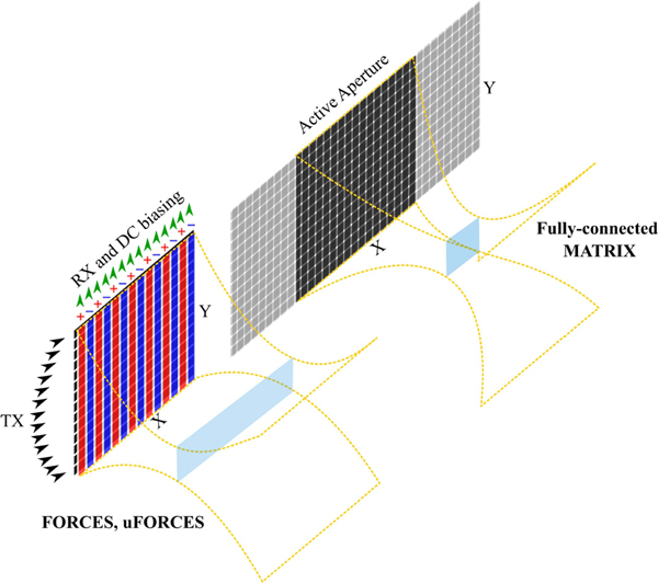
This article hypothesizes that the sparsely coded SAI scheme implemented on a bias-sensitive TOBE array (called uFORCES) will exhibit comparable or improved resolution to a state-of-the-art fully wired matrix probe. Thus, three different imaging schemes were investigated: 1) FORCES and 2) uFORCES were implemented with a TOBE array. 3) A walking aperture scheme on a fully wired 2-D array (simulating a matrix probe) was implemented for comparison. These imaging schemes are briefly illustrated in Fig. 1. The active aperture is kept the same in all simulations. A walking aperture scheme is selected for the matrix probe as it represents the best possible image quality that could be achieved (in contrast to sector scanning). Additionally, unlike a true matrix probe which implements microbeamformer approximations, we simulate a fully wired array and beamforming constrained to a quadratic delay profile associated with the paraxial approximation.
Fig. 1.
Illustration of different imaging schemes investigated in this article. The size of the active aperture for fully connected matrix probe is the same as the aperture size for TOBE arrays.
A. FORCES and uFORCES
FORCES has successfully been introduced and implemented in [20] and [21], In summary, as shown in Fig. 1, FORCES transmits delayed pulses on rows to achieve elevational focusing and receives along columns. The columns are bias coded with Hadamard patterns for each transmit/receive event. For a 128 × 128 TOBE array, FORCES uses 128 transmit/receive events. Decoding the data (using an inverse Hadamard matrix) recovers a full transmit-receive SAI dataset for the columns of the TOBE array. The role of the rows and columns can be interchanged to create cross-plane imaging. Electronic steering enables the acquisition of a 3-D image.
uFORCES is introduced here as an ultrafast variant of FORCES using TOBE arrays. uFORCES will enable steerable B-scan acquisition with only a few transmit events while achieving near-ideal synthetic aperture transmit and receive focusing everywhere in the image. Here, we describe the uFORCES approach and demonstrate using simulations that uFORCES with TOBE arrays has the potential to achieve improved in-plane resolution and comparable out-of-plane resolution as state-of-the-art matrix probes relying on micro beamforming.
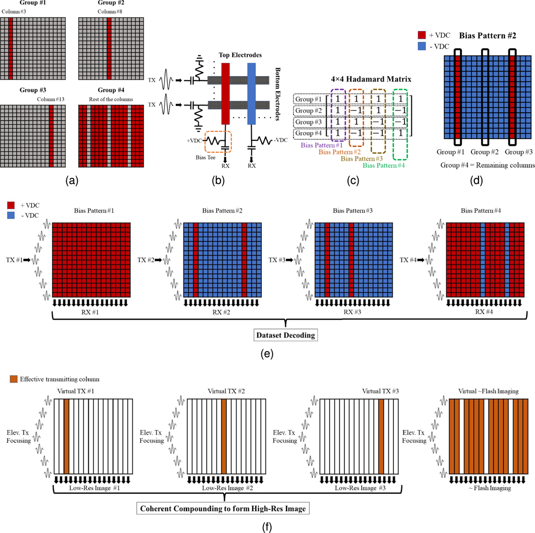
Fig. 2 illustrates the uFORCES scheme for a 16×16 TOBE array. FORCES would require as many transmit/receive events as columns in the array. However, our proposed uFORCES approach can achieve imaging with fewer transmit events. In this method, we select sparsely spaced columns as the desired transmitters. One might wonder if we could transmit on a single column at a time. However, the problem is that if we only biased one column and transmitted along rows for elevational focusing, the unbiased columns would be insensitive to receiving signals. Instead, we bias all the columns, but with a set of bias patterns. In this way, we can receive signals from every column after each transmit event. Previously we did this with bias patterns selected from rows or columns of a Hadamard matrix [20], In uFORCES, however, we first group elements into grouping, including sparse transmitters and remaining element groupings. In Fig. 2(a), we choose columns 3, 8, and 13 as sparse transmitters and all the remaining elements as a fourth grouping. Here, we arbitrarily use columns 3, 8, and 13 as sparse transmitters for illustrative purposes (as they are separated by a regular interval, in this case, five columns) but other choices are possible. As before, delayed pulses are sent on the rows to focus the beam in elevation. However, instead of selecting bias patterns from an N × N Hadamard matrix for an N × N TOBE array, (in this case, N = 16), we now select bias patterns from a smaller (e.g., M × M, where M < N) Hadamard matrix. In this example, we do this with a 4 × 4 Hadamard matrix. For example, the second column of a 4 × 4 Hadamard matrix is [1 −1 1 −1], Thus, we apply positive, negative, and positive bias voltages to sparse transmitting columns on columns 3, 8, and 13. Then, we apply a negative bias voltage to all remaining elements as illustrated in the dc pattern #2 in Fig. 2(d). We apply a biasing pattern in this manner for each of the four transmit events. After the complete set of transmit events has been sent, recovered column channel data (inverted when acquired from a negatively biased column) is aperture-decoded using the inverse of the 4 × 4 Hadamard matrix. This then recovers a column data synthetic aperture dataset. As shown in Fig. 2(f), for this example, it recovers channel data as if column 3 first transmitted (with an elevational focus) then data was received on all columns, then column 8 then column 13. A final dataset is recovered which is similar to a plane wave excitation with some of the sparse columns missing (however, it is not used in the beamforming). The synthetic aperture datasets are then reconstructed to form a synthetic aperture image, which is focused on transmission and received everywhere in the scan plane. This is accomplished by beamforming a low-resolution image from each sparse-transmitting element and then coherently compounding the low-resolution images to form a high-resolution image.
Fig. 2.
uFORCES imaging scheme illustrated with a 16 × 16 TOBE array using four transmits (four bias patterns), (a) Column groupings for arbitrarily selected sparse transmitters, (b) Schematic of the top and bottom electrodes and their bias tees, and (c) 4 × 4 Hadamard matrix for this example. One column of the Hadamard matrix is used as a biasing pattern for each transmit event, (d) Applied coded bias voltage pattern associated with bias pattern 2, (e) Illustration of the uFORCES imaging scheme for all the bias pattern sequences with transmitting on the rows and receiving on the columns, and (f) sparse synthetic aperture effective dataset and reconstruction scheme after aperture decoding with an inverse Hadamard matrix.
Steering the scan plane in elevation is also possible when acquiring a volumetric image. In previous sparse SAI work using linear arrays, as few as five sparse transmitting elements had been shown to produce image quality comparable to full SAI [3], Thus, in what follows, we will use uFORCES with 8, 16, or 32 groupings. An eight-transmit uFORCES scheme would recover a synthetic aperture dataset with seven sparse transmitting columns.
While our approach requires far fewer transmit events than FORCES, there will be a tradeoff between imaging speed and SNR. The higher the imaging speed, the lower the SNR would be since the effective active aperture with only a few sparse transmitting elements is small. The image quality can be dynamically changed during the imaging by adjusting the number of transmit events where needed.
The comparison is conducted in field II [24] with 128 × 128 arrays with parameters summarized in Table I. To form a TOBE array, the RF signals of each element on the columns and rows are added up. The effect of the dc bias switching for each pattern was applied to each individual element in field II by alternating the index of the apodization between 1 and −1 denoting positive and negative bias voltages, respectively. Additionally, this apodization is modified with a hamming-weighted shape, which is shown to reduce the artifacts caused by side lobes compared with the unity-weighted apodization. The hamming-shaped apodization can potentially be implemented by tapering the electrodes during the fabrication of the TOBE arrays.
TABLE I.
Parameter Used in Field II Simulations
| Parameter | Value |
|---|---|
|
| |
| Speed of sound | 1540 m/s |
| Center frequency | 10 MHz |
| Sampling frequency | 100 MHz |
| Kerf | 15 μm |
| Pitch | 150 μm |
| Number of excitation cycles | 1 |
| 2D array size | 128×128 |
B. Matrix Probe
In this article, the matrix probes are considered as a 2-D fully connected array which performs a walking aperture imaging scheme with either wide or narrow-focused transmit beams and with narrow dynamic-receive beamforming used in reception. In practice, the considered walking aperture implemented on a fully connected 2-D array will perform better than an actual matrix probe as no microbeamformer approximation is used. This was done to demonstrate the best possible performance of a matrix probe for comparison against our uFORCES simulations with TOBE arrays. As mentioned, the matrix probes used receive focusing with a dynamic quadratic delay profile as constrained by the paraxial approximation. This approximation limits reconstructions to f-numbers greater than unity without reconstruction artifacts. In contrast, our uFORCES synthetic aperture approach required no such restrictions.
C. Imaging Targets
The imaging simulations are conducted on two different phantoms. The first phantom, which is composed of 15-point scatterers located at depths of 15, 20, 25, 30, and 35 mm (on- and off-axes by 3 mm), was used for the simulation. However, the on-axis scatterers were only used for calculating the point spread functions (PSFs) and associated spatial resolution for each imaging scheme. Another phantom with 100000 scatterers and different cyst sizes were used for comparing the contrast and contrast-to-speckle ratio (CSR). The simulations were performed on a computer with a six-core processor and 32 GB of memory. However, due to the slow simulation, only walking aperture and uFORCES imaging were performed on the cyst phantom knowing that FORCES would give almost the same resolution as uFORCES with some improved SNR due to the more signal averaging in the coherent compounding.
The contrast-detail phantom images of different imaging schemes are compared with each other in terms of CSR, which are calculated using the following expressions [25]:
| (1) |
| (2) |
in which and are the average signals inside and outside of the area of interest, respectively, and denotes the standard deviation.
III. EXPERIMENTAL METHODS
A. Bias-Sensitive Ultrasound Transducer Based on PMN-PT
Bias-sensitive TOBE arrays allow for coding/decoding the aperture to be able to address each column and row individually by using, i.e., Hadamard matrix biasing. Unlike the piezoelectric materials, the bias-sensitive ultrasound transducers made of electrostrictive materials show no piezoelectricity effect unless a dc bias voltage is applied [20], [21], Lead magnesium niobate (PMN) with low lead titanate (PT) doping is an electrostrictive material that is naturally unpolarized at around room temperature and becomes polarized by applying a dc bias voltage (PMN38, TRS Technology, State College, PA, USA). These materials can also be made transparent/translucent when polished on both sides that potentially can be used in through-illumination photoacoustic applications [26], [27], CMUT is another bias-sensitive transducer that uses electrostatic forces between two clamped plates to generate acoustics which some of their applications in TOBE configurations have been demonstrated recently [8],
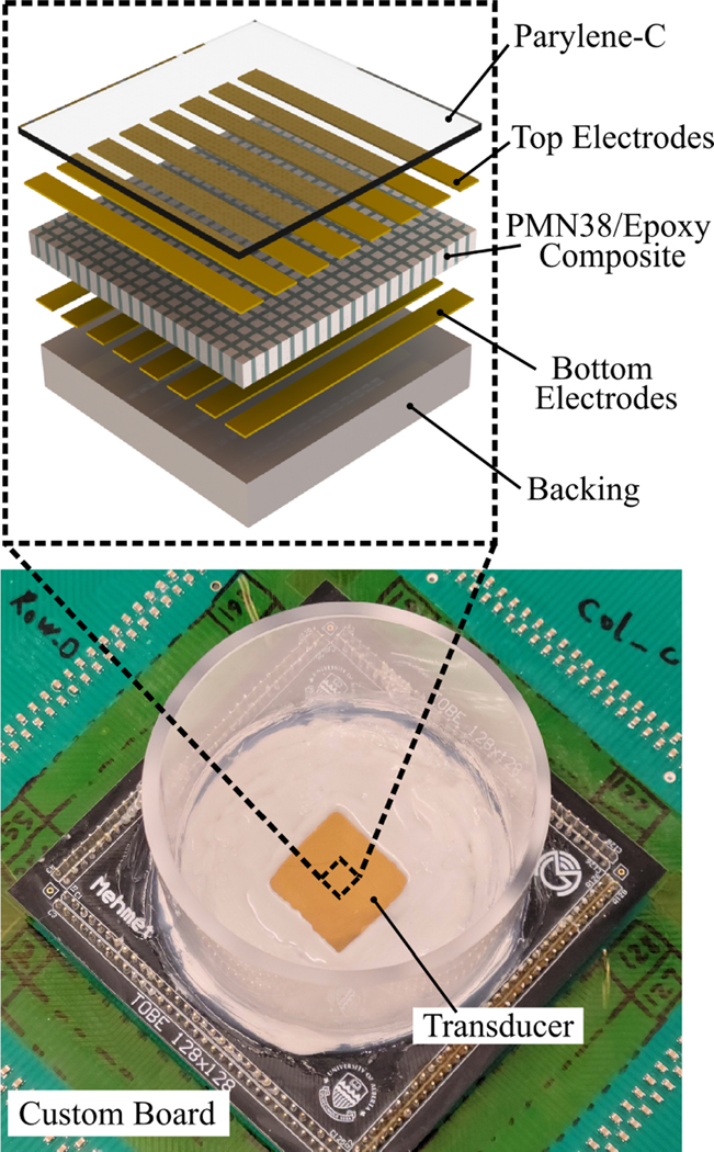
In this work, a 128 × 128 electrostrictive TOBE array was fabricated to perform uFORCES imaging. This is the largest such TOBE array fabricated to date. The fabrication was conducted with steps similar to those previously described [18] for 64 × 64 arrays. As shown in Fig. 3, the transducer is composed of a PMN-PT/epoxy composite material sandwiched in between the top and bottom electrodes which are orthogonal to each other. A quarter-wavelength parylene-C layer was deposited on top as the matching layer and a thick alumina-loaded epoxy on the back serves as a backing layer. Transducer fabrication was performed in the nanoFAB facility at the University of Alberta, Edmonton, AB, Canada. The fabricated array was wire-bonded to a printed circuit board on both the front- and back-sides, which was then connected to an interfacing board connected to our Verasonics Vantage ultrasound platform for testing and imaging. Custom high-voltage biasing electronics were used to apply bias patterns as controlled by the Verasonics system.
Fig. 3.
Photograph of the fabricated 128 × 128 TOBE array with the schematic exploded view showing its cross section.
B. Array Characterization and Testing
Prior to Parylene-C deposition, the bias sensitivity of the fabricated transducer was tested by measuring the input impedance for a few different dc biases. The bias-sensitivity for a smaller array was demonstrated previously in [21].
To measure the impedance of the array, we used a Keysight E4990A impedance analyzer and recorded both the magnitude and phase as a function of frequency in an air environment. A bias tee (Minicircuits ZFBT-4R2GW-FT+) was used to apply varying bias voltages for experiments. In performing these experiments we grounded all connections on one side of the array while testing one channel on the other side. These data were used to calculate the resonance () and antiresonance () frequencies and the associated electromechanical coefficient, , as follows [28]:
| (3) |
C. Bias Switching Electronics
A custom-made bias-switching electronics board was used for biasing the fabricated array. Each channel on the rows and columns is connected to a set of high-voltage MOSFET-based switches controlled by a 2–4 decoder. So each channel can be individually programmed to get four stages: positive high voltage, negative high voltage, ground, and high impedance (open circuit). A bias tee made of a capacitor and a resistor is used for each channel. The dc bias voltages from the dedicated electronics switches get to the channels through the resistors of the bias tees. The capacitor on the bias tee blocks the dc voltages from reaching the Verasonics platform while letting the Tx and Rx signals pass through it. The bias-switching electronics can switch from −175 V to +175 V in 648 ns without load [29], However, this switching speed drops to 300–400 μs when the array is connected to the biasing board, constrained by the high-value resistors used in the bias tees.
D. Channel Mapping
A script was written to find shorted elements in fabricated TOBE arrays. It applies a bias voltage to one channel at a time and grounds all other rows/columns. The high-voltage power supply has a current limit set to about 5 mA.
The script loops through all channels defined for the transducer and the user is asked to make a decision for each channel whether the channel is shorted or not. Usually, a channel is considered to have no shorts if the current drawn is less than 1 mA. Once the mapping procedure is finished, any shorted channel is set to a high impedance state to prevent damage to the electronics or array during imaging.
E. Immersion Testing and Imaging Experiments
To test the arrays for uFORCES imaging, we glued a water tank to the PCB with a transducer and conducted immersion experiments using a Verasonics Vantage 256 system.
We first characterized the transducer by performing a pitch-catch experiment using single channels. This experiment was used to characterize the center frequency and the bandwidth of the array.
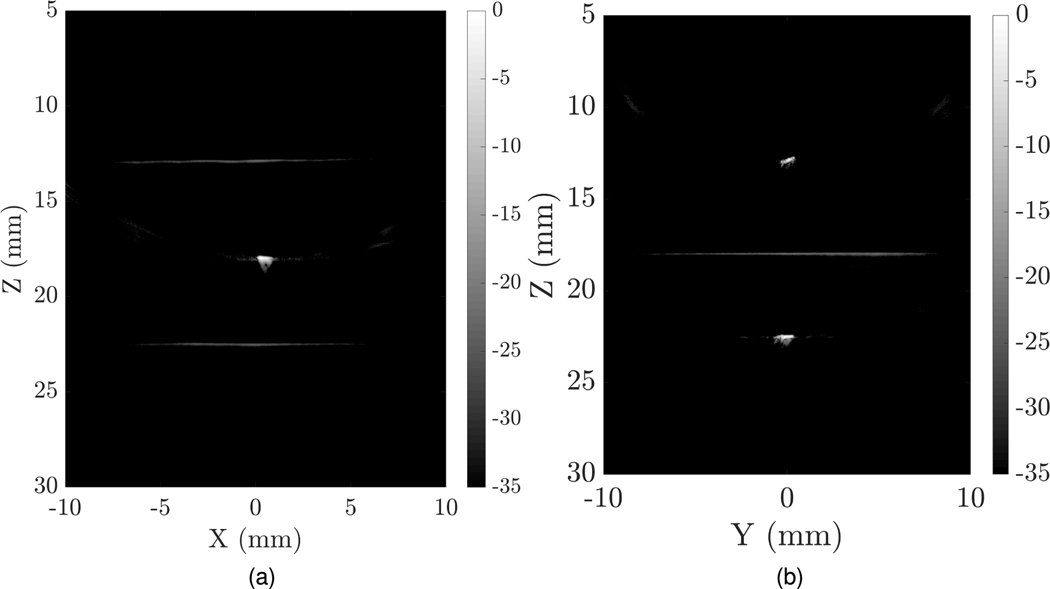
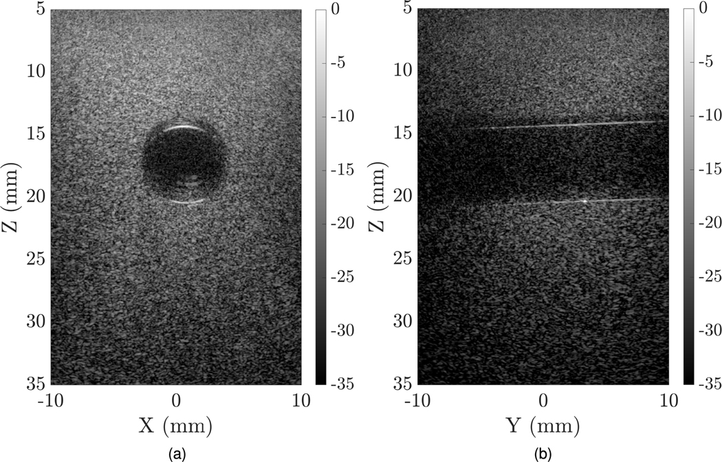
Next, We imaged cross-wire targets consisting of three 25-μm wire-bonding wires with approximately 5 mm spacing, and the middle wire being 90° rotated from the others. The purpose of these experiments was to demonstrate preliminary evidence that the uFORCES methods with TOBE arrays could achieve high-resolution images experimentally. We also imaged a tissue-mimicking phantom made of 85% water, 10% gelatin, and 5% cornstarch with a 6-mm-diameter hole in the center.
IV. RESULTS
A. Simulated Point Spread Functions
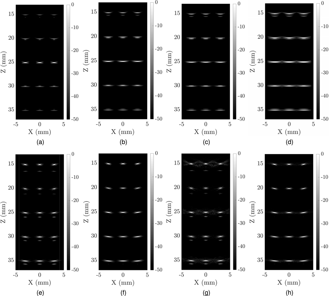
Fig. 4 illustrates the PSFs of different imaging schemes simulated in field II with a 128 × 128 array. All the images are plotted in a 50-dB dynamic range. The matrix probe walking aperture schemes use narrow dynamically focused reception with an applied 2-D Hanning apodization. We used both narrow and wide transmit beams without any apodizations. The narrow beam was created by using the entire active 128 × 128 elements, while for the wide beam, only 32 elements in the center were used. Both wide and narrow transmit/receive beams are focused at 25 mm depth. We reconstructed images with 501 A-scan lines. However, to compare with sparse-transmitting uFORCES schemes, we considered reducing the number of transmit events. We tested 501, 24, and eight transmit event imaging using these matrix simulations.
Fig. 4.
In-plane PSFs of different imaging schemes; (a) matrix probe with narrow transmit beam of 501 transmit events, (b) matrix probe wide with wide beam of 501 transmit events, (c) matrix probe with wide beam of 24 transmit events, (d) matrix probe with wide beam of eight transmit events, (e) FORCES without apodization with 384 transmit event, (f) FORCES with apodization with 384 transmit events, (g) uFORCES without apodization with 24 transmit events, and (h) uFORCES with apodization with 24 transmit events.
The images obtained by FORCES and uFORCES methods used three elevations (and azimuthal) focusing depths at 15, 25, and 35 mm. Images acquired using these different transmit focal depths were then stitched together using a Gaussian-weighted blending algorithm.
The FORCES scheme requires 128 biasing patterns multiplied by 3 focal zones for an overall 384 transmit/receive events. In contrast, the eight-transmit uFORCES scheme only requires 8 × 3 = 24 transmit/receive events making it 16 times faster.
The calculated lateral and axial resolutions for the PSFs are summarized in Table II. The axial and lateral resolutions are estimated with an error of ±2μm and ±5 μm, respectively. As can be seen, uFORCES PSFs in Fig. 4(g) and (h) are similar to FORCES PSFs in (e) and (f). Apodization helped reduce some edge-wave reconstruction artifacts. Lateral spatial resolution of FORCES and uFORCES reconstructions was improved compared with matrix probe simulations using wide or even narrow transmit beams.
TABLE II.
In-Plane SNR and Resolution Measurements for Each Imaging Scheme With and Without the Noise
| Scheme | Total Number of Transmits | Point distance (mm) | Lateral FWHM Resolution (μm) | Axial FWHM Resolution (μm) |
|---|---|---|---|---|
| Walking Aperture (Narrow Beam) | 501 (Focusing at 25 mm) | 15 | 544 | 92 |
| 20 | 556 | 91 | ||
| 25 | 284 | 95 | ||
| 30 | 334 | 91 | ||
| 35 | 706 | 91 | ||
| Walking Aperture (Wide Beam) | 501 (Focusing at 25 mm) | 15 | 476 | 100 |
| 20 | 488 | 93 | ||
| 25 | 528 | 995 | ||
| 30 | 598 | 94 | ||
| 35 | 658 | 93 | ||
| 24 (Focusing at 25 mm) | 15 | 554 | 94 | |
| 20 | 570 | 97 | ||
| 25 | 588 | 97 | ||
| 30 | 648 | 95 | ||
| 35 | 722 | 94 | ||
| FORCES | 3×128 (Focusing at 15, 25, 35 mm) | 15 | 266 | 101 |
| 20 | 258 | 93 | ||
| 25 | 340 | 99 | ||
| 30 | 384 | 100 | ||
| 35 | 410 | 96 | ||
| uFORCES | 3×8 (Focusing at 15, 25, 35 mm) | 15 | 233 | 114 |
| 20 | 256 | 94 | ||
| 25 | 296 | 94 | ||
| 30 | 370 | 96 | ||
| 35 | 390 | 93 |
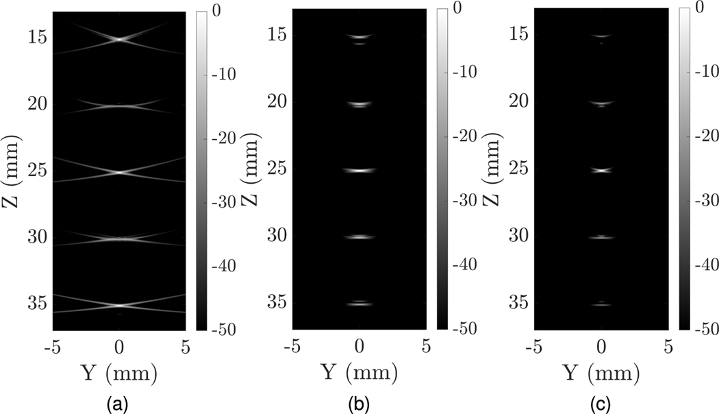
To assess the elevational scanning performance of the uFORCES scheme, we performed simulations to render the Y Z-scan plane of a TOBE array in comparison with a matrix probe. The results are shown in Fig. 5. In the uFORCES simulation in Fig. 5(a), we used three elevational transmit focal zones as discussed above and used eight transmit events per focal zone. As can be seen, elevational spatial resolution was comparable to the matrix probe but the uFORCES scenario exhibited more reconstruction artifacts since unfocused receive elements were used in elevation. Nevertheless, transmit elevational focusing, including using three elevation focal zones, produce reasonable elevation point-spread functions given the limitations of row-column-only addressing.
Fig. 5.
Elevationally scanned (YZ) plane imaging comparisons using (a) a 128 × 128 λ-pitch TOBE array and uFORCES, (b) 128 × 128 matrix probe using a wide beam excitation in azimuth, and (c) 128 × 128 matrix probe with narrow beam excitation in azimuth.
B. Contrast-Detail Phantom Simulations
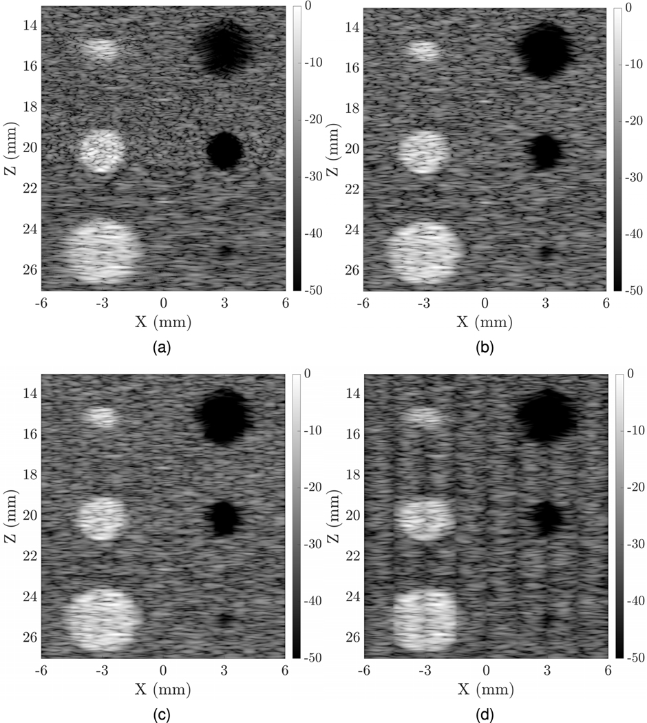
The walking aperture simulation was first done on the phantom with a narrow beam and single focus point at 20 mm depth. A total of 601 lines were scanned between −6 and 6 mm lateral distance (x-axis) to form a 2-D image of the phantom. We also simulated a wide transmit beam using the same number of transmit events, and wide-beam excitation using 24 and eight transmit events along with parallel beamforming (Fig. 6). These fewer transmit events were simulated to compare against uFORCES schemes having eight and 24 transmit events. Time-gain compensation was applied to achieve roughly uniform brightness with depth. Vertical stripes are seen in some of the wide transmit images owing to multiple receive lines reconstructed for each wide transmit event. Commercial systems will undoubtedly use improved blending in post-processing to ensure a more uniform image quality but this was not pursued in this article for simplicity.
Fig. 6.
Comparison of fully wired matrix array walking aperture imaging using (a) 601 transmit events and a narrowly focused transmit beam, (b) 601 transmit events and a wide transmit beam (c) 24 transmit events and parallel focusing of multiple lines per transmit event (d) eight transmit events and parallel focusing of multiple lines per transmit event. The eight- and 24-transmit event simulations are designed to compare against eight- and 24-transmit event uFORCES simulations.
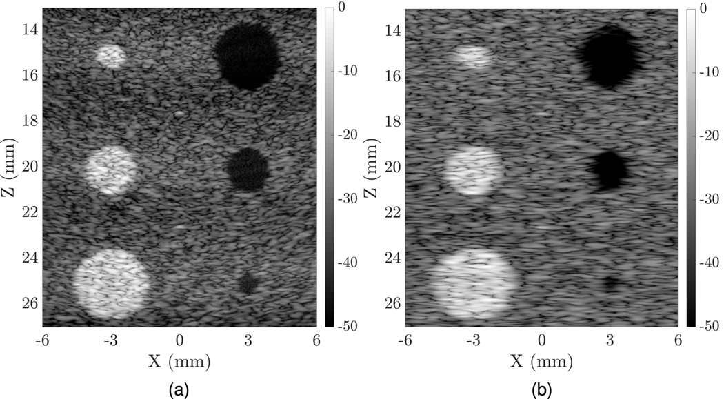
Since the simulations of such a large phantom were quite slow, only uFORCES imaging (which required fewer transmit-receive events than FORCES) was performed on the cyst phantom with three focal zones (and eight transmits per zone) for a total of 24 transmit/receive events, as shown in Fig. 7.
Fig. 7.
Simulated comparisons of a contrast detail phantom imaged using (a) TOBE uFORCES and (b) matrix probe wide-beam walking aperture. In both cases, a 10-MHz 128 × 128 lambda pitch array was used but the TOBE array used only row and column addressing. Here, the uFORCES simulation used eight transmit events per focal zone, and stitched results from three elevational focal zones. This required a total of 24 transmit events, with coherent compounding needed over only eight transmit events.
The CSR for both uFORCES and matrix probe simulations are presented in Table III. Visually, uFORCES simulations look crisper owing to improved spatial resolution. Note that the measured CSRs are not better for uFORCES compared with the matrix probe for the middle lesions since this is where the matrix probe is focused on both transmit and receive. However, for the top and bottom lesions, contrast is improved or similar for uFORCES compared with the matrix simulations, and CSRs are similar.
TABLE III.
Comparison of uFORCES and Matrix Probe in Cyst Phantom Simulation in Terms of Contrast and CSR
| Scheme | Cyst Phantom | |||||||||||
|---|---|---|---|---|---|---|---|---|---|---|---|---|
| Z = 15 mm | Z = 20 mm | Z = 25 mm | ||||||||||
| Left | Right | Left | Right | Left | Right | |||||||
| Contrast | CSR | Contrast | CSR | Contrast | CSR | Contrast | CSR | Contrast | CSR | Contrast | CSR | |
| Narrow Beam | 6.7 | 1.4 | −0.8 | −1.3 | 13 | 1.4 | −0.8 | −0.8 | 8.1 | 1.5 | −0.5 | −0.6 |
| Wide Beam (601) | 7.6 | 1.4 | −0.8 | −1.4 | 11.2 | 1.6 | −0.7 | −0.9 | 8.4 | 1.6 | −0.5 | −0.7 |
| Wide Beam (24) | 7.6 | 1.4 | −0.8 | −1.4 | 11.3 | 1.6 | −0.7 | −0.9 | 8.4 | 1.6 | −0.5 | −0.7 |
| Wide Beam (8) | 5.1 | 1.4 | −0.8 | −1.4 | 11.9 | 1.4 | −0.6 | −0.6 | 9 | 1.5 | −0.5 | −0.6 |
| uFORCES | 10.5 | 1.4 | −0.8 | −1.1 | 8.9 | 1.4 | −0.7 | −0.9 | 8.6 | 1.6 | −0.5 | −0.6 |
C. Impedance Testing
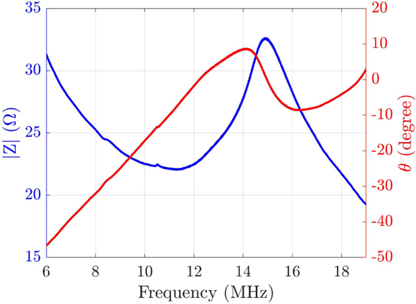
The unloaded input impedance of the fabricated transducer with an applied dc bias of 120 V is demonstrated in Fig. 8. The fabricated transducer showed a maximum kt value of ~0.67 for a voltage of 120 V. As expected, the fabricated bias-sensitive TOBE array shows no piezoelectric effect for a 0-V bias voltage while the sensitivity and polarity scale with the bias voltage amplitude and polarity as reported in Fig. 4 in [21],
Fig. 8.
Impedance measurement of a single channel of the fabricated arrays done in air.
D. Pulse-Echo Testing
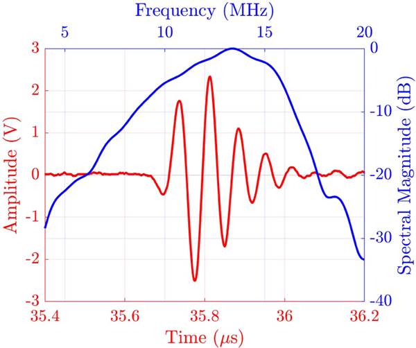
Fig. 9 shows results from an immersion transmit test, where a single channel of the array was used to transmit ultrasound, which was reflected from an aluminum plate to be received by the same channel. To this end, a pulser/receiver with an excitation spike voltage of −180 V and a receive gain of 10 dB at a frequency range of 5–20 MHz was used (PANAMETRICS-NDT, 5073PR). The center frequency of the array was measured to be 13.6 MHz with −6-dB bandwidth of 51%.
Fig. 9.
Temporal and frequency response of a single channel from the fabricated array in pulse-echo experiment.
E. Experimental Crossed-Wire and Phantom Imaging
Experimental imaging of wire targets was done with a fabricated 128 × 128 TOBE array using bias voltages of ±100 V. uFORCES was implemented using a custom imaging script which sent bias-voltage patterns to custom 256-channel high-voltage biasing electronics. The image shown in Fig. 10 was obtained by stitching images with three different transmit elevational focal zones. Here, we implemented uFORCES with 32 transmits per elevational focal depth. This array had 20–25 dead elements per side and improved results are expected with an improved array. We also performed the same imaging scheme on a tissue-mimicking phantom with a hole in the center. uFORCES with 32 transmit events and an elevational focal zone at 16 mm was used for the imaging, as shown in Fig. 11. This is the preliminary result obtained by an array with a considerable number of channels shorted. A higher quality image is desired with a well-performing array.
Fig. 10.
Experimental cross-plane uFORCES images of a cross-wire phantom using 32-transmits per elevational focal zone and three such focal zones at 12, 18, and 22 mm depths, (a) XZ plane, (b) YZ plane. These images were obtained by electronically reversing the roles of rows and columns and were obtained without mechanically moving the transducer.
Fig. 11.
Cross-plane experimental uFORCES image of a tissue-mimicking phantom using 32-transmits with elevational focal zone at 16 mm depth, (a) XZ plane, (b) YZ plane. These images were obtained by electronically reversing the roles of rows and columns and were obtained without mechanically moving the transducer.
V. DISCUSSION
This article introduces uFORCES as a means to form images much faster than with FORCES, but with little degradation in image quality. Whereas FORCES requires N transmit events for an N × N array, uFORCES requires less, and we used as few as eight such transmit events for a 128 × 128 TOBE array. This represents a speedup of 16-fold using uFORCES compared with FORCES for this array.
Our uFORCES simulations demonstrate improved in-plane spatial resolution compared with similar dimension fully wired matrix probes with a walking aperture imaging scheme. We believe this can be explained by two key reasons. First, uFORCES effectively implements in-plane SAI, which achieves focusing in transmit and receive everywhere in the scan plane. This is in contrast to the scanning scheme used by our matrix probe simulations, where a single-transmit focal depth is used per transmit event, and away from this focal zone, the transmitted wave is unfocused. Second, the matrix beamforming is limited to a quadratic delay profile as constrained by the paraxial approximation. As such, focusing is not well achieved without artifacts for f-numbers smaller than unity. In contrast, uFORCES achieves SAI, which is not limited by the paraxial approximation and can achieve fine focusing even for low f-numbers.
Elevational focusing with uFORCES is seen to exhibit more beamforming artifacts compared with matrix simulations but the resolution is comparable. uFORCES is limited by unfocused elevational receive elements, even though there is an elevational transmit focus. As such, we used multiple elevational transmit focal zones to improve the depth of field. It should be noted that elevation stitching using multiple transmit focal zones could be achieved without the need for coherent compounding. Thus, even though we used a total of 24 transmit events, coherent compounding was needed over only eight such transmit events. This is important as tissue motion can lead to degradation of coherent compounding unless it can be done quickly relative to tissue motion.
With current bias tees with a switching time of 300–400 μs, we achieved an imaging rate of > 300 fps when using eight-transmit uFORCES. With future improvements in bias switching electronics, we anticipate thousands of frames per second. Thus, with improved electronics and bias tees, eight-transmit uFORCES with an 8-kHz PRF would result in kHz B-scan imaging rates. In principle matrix probes can transmit wide beams and execute parallel receive focusing to reconstruct many lines at once. However, the fine delays in the microbeam-former stage are technically valid for a single-receive line-of-sight, and the more parallel beamforming the worse the reconstruction error.
In practice, matrix probes will probably not use the walking aperture scheme simulated here. They will likely use all the elements and implement a sector-scanning approach. However, sector-scanning will lead to even more artifacts owing to grating lobes becoming more significant at higher steering angles. The purpose of using a walking aperture scheme here was to compare TOBE uFORCES against the best possible theoretical matrix probe and associated imaging scheme.
Imaging advantages over matrix probes are only demonstrated in simulation for now. These simulations further included array apodization. This apodization was not yet implemented in array fabrication, but work is underway to do so. Such apodization is important to mitigate edge-wave artifacts and improve imaging point-spread functions.
Experiments were conducted with unapodized 128 × 128 arrays. Fabrication of these large arrays was found to be highly non-trivial and the tested arrays had 20–25 shorted or dead channels per side, which was a source of some image quality degradation. If a robust fabrication procedure for large TOBE arrays can be developed, these arrays could hold great promise for significant developments in preclinical and clinical imaging applications.
Signal-to-noise is degraded using uFORCES compared with FORCES since uFORCES uses a sparse SAI scheme. Strategies for improving signal-to-noise ratio should be investigated in future work and could include coded excitation schemes, element binning, and so on.
Two-dimensional arrays for high-frequency applications do not yet exist commercially. Our technology could achieve this and lead to advances in preclinical ultrasound.
Our current experimental results were achieved using a tabletop testbed setup with an integrated water tank. This enables rapid prototyping of new arrays and new imaging schemes but is not yet practical for imaging. Future work should develop handheld, endoscopic, and other form factors for clinical and preclinical applications.
TOBE arrays, unlike matrix probes, also have great potential for scaling up to large arrays of unprecedented size. For this, a robust fabrication process is needed. If successful, this could lead to better deep imaging because the numerical aperture will be improved. It will also enable greatly expanded fields of view and we envision future large 1024 × 1024 or larger arrays for whole organ imaging.
For TOBE probes and uFORCES to be realized, nontrivial fast bias-switching electronics are needed, which are absent in conventional ultrasound systems. While there will be additional development complexity and cost associated with these electronics, they can be used with any TOBE array. By taking the electronics complexity out of the probe head, it should greatly simplify the development costs of the probes.
TOBE arrays are additionally simple enough to be wearable. This prospect could open up opportunities for longitudinal imaging that were previously not possible.
Future work should take advantage of the ultrafast imaging capabilities demonstrated with uFORCES for novel flow-imaging and shear-wave imaging opportunities.
For the full potential of TOBE arrays to be realized, highly parallelized computing architectures will be needed which may be absent on even state-of-the-art ultrasound platforms. However, the massive explosion of GPU computing accelerated by the deep-learning era will surely prove essential to future high-resolution, massive field-of-view 3-D and 4-D imaging technologies of the future. We envision that TOBE array technology will be an important component of this future wave. Successful realization of uFORCES depends on several practical factors. Ideally, the sensitivity of elements will be uniform but practically, process variations may lead to different responses from different elements. These variations may lead to image quality degradation. Calibration and compensation algorithms could help mitigate some of these problems. Shorted channels could be a source of imaging artifacts. In practice, we assigned the shorted channels to high impedance with our custom bias-switching electronics.
VI. CONCLUSION
We have simulated and experimentally demonstrated our newly proposed uFORCES imaging scheme using 128 × 128 TOBE arrays. One might presume that since these arrays provide only row and column addressing that the achievable image quality might be compromised compared with a fully wired matrix probe with integrated microbeamformers. However, we have shown the opposite, since our approach can achieve transmit and receive focusing everywhere in the scan plane and since we are not limited by the paraxial approximation. Moreover, our approach can achieve ultrafast imaging rates, unlike matrix probes. With these promising results, we believe that there is a bright future for TOBE arrays as a potential candidate to finally provide clinicians with the 3-D image quality they need. We also envision a future with large-scale and wearable TOBE arrays which will bring new opportunities for the future of medicine.
Acknowledgments
This work was supported in part by Alberta Innovates (AB Innovat) under Grant CASBE 212200391, in part by NSERC under Grant A AC AS BE 567531, in part by AB Innovat [Accelerating Innovations into CarE (AICE) - Concepts (AICEC)] under Grant 202102269 and Grant RGPIN-2018-05788, in part by the Canadian Institutes of Health Research (CIHR) under Grant PS 168936, in part by the Mathematics of Information Technology and Complex Systems (MITACS), CliniSonix Inc., and in part by NIH under Grant EITTSCA R21EY033078.
Biographies

Mohammad Rahim Sobhani (Student Member, IEEE) was born in Tabriz, Iran. He received the B.Sc. degree (Hons.) in biomedical engineering (bio-electric) from the Sahand University of Technology, Tabriz, in 2012, and the M.Sc. degree in electrical and electronics engineering from Özyeǧin University, Istanbul, Turkey, in 2015. He is currently pursuing the Ph.D. degree with the Department of Electrical and Computer Engineering, University of Alberta, Edmonton, AB, Canada.
He is currently a Graduate Assistant with the Department of Electrical and Computer Engineering, University of Alberta. His current research interests include the development of large-area top-orthogonal-to-bottom electrode arrays, transparent ultrasound transducers, and microfabrication.

Mahyar Ghavami (Student Member, IEEE) was born in Tabriz, Iran. He received the B.Sc. degree in mechanical engineering from the University of Tabriz, Tabriz, and the M.Sc. degree in mechanical engineering from Tarbiat Modares University, Tehran, Iran, in 2014 and 2017, respectively. He is currently pursuing the Ph.D. degree with the Department of Electrical and Computer Engineering, University of Alberta, Edmonton, AB, Canada, under the supervision of Dr. Zemp.
His research focuses on the development of ultrasound transducers for biomedical applications.

Afshin Kashani Ilkhechi (Member, IEEE) was born in 1989. He received the B.Sc. degree in electronic engineering from the University of Tabriz in 2012, the M.Sc. degree in electronic engineering from the Sahand University of Technology in 2014, and the Ph.D. degree in biomedical engineering from the University of Alberta, Edmonton, AB, Canada, in 2022.
He has authored and coauthored numerous journals and conference papers in the field of microsystems and microelectromechanical systems, and biomedical imaging technology. He is currently working on state-of-art biomedical devices to treat eye disease mainly wet-stage age-related macular degeneration and diabetic retinopathy.
Dr. Ilkhechi is also a reviewer of a number of journals and conferences in his fields of interest.

Jeremy Brown (Member, IEEE) was born in London, ON, Canada, in 1978. He received the B.Sc.Eng. degree in engineering physics and the Ph.D. degree in applied physics from Queen’s University, Kingston, ON, Canada, in 2001 and 2005, respectively.
From 2006 to 2008, he was a Postdoctoral Researcher with the Sunnybrook Health Sciences Center, Toronto, ON, Canada. In 2008, he joined as a faculty member in biomedical engineering with Dalhousie University, Halifax, NS, Canada, where he is currently cross appointed to the Department of Electrical Engineering. In 2009, he joined the Department of Surgery, Nova Scotia Health Authority, Halifax, as an Affiliated Scientist. His research in high-frequency ultrasound is focused on the development of very high-resolution microfabricated imaging endoscopes for guided surgical applications and low-frequency ultrasound is focused on developing miniature highly focused therapeutic transducers for precision tissue ablation. His research interests include piezoelectric transducer design, fabrication, and characterization for both ultrasonic imaging and therapeutic applications and all of the associated electronic hardware required to drive capture, and process the ultrasonic signals.

Roger Zemp (Member, IEEE) received the B.Sc. degree in physics from the University of Alberta, Edmonton, AB, Canada, in 1998, the M.A.Sc. degree in electrical and computer engineering from the Institute of Biomaterials and Biomedical Engineering, University of Toronto, Toronto, ON, Canada, in 2000, and the Ph.D. degree in biomedical engineering from the University of California at Davis, Davis, CA, USA, in 2004.
From 2004 to 2006, he was a Postdoctoral Researcher with the Optical Imaging Laboratory of Prof. Lihong Wang, Texas A&M University, College Station, TX, USA. From 2006 to 2007, he was with Washington University in St. Louis, St. Louis, MO, USA. He is currently a Professor with the Department of Electrical and Computer Engineering, University of Alberta. His current research interests include micromachined ultrasound transducers, photoacoustic tomography, photoacoustic microscopy, biomedical optics, ultrasound-aided biomarker release, ultrasound-aided drug and gene delivery, and novel technologies for molecular and functional imaging with an emphasis on cancer.
Contributor Information
Mohammad Rahim Sobhani, Department of Electrical and Computer Engineering, University of Alberta, Edmonton, AB T6G 2R3, Canada.
Mahyar Ghavami, Department of Electrical and Computer Engineering, University of Alberta, Edmonton, AB T6G 2R3, Canada.
Afshin Kashani llkhechi, Department of Electrical and Computer Engineering, University of Alberta, Edmonton, AB T6G 2R3, Canada.
Jeremy Brown, Department of Electrical and Computer Engineering, Dalhousie University, Halifax, NS B3H 4R2, Canada.
Roger Zemp, Department of Electrical and Computer Engineering, University of Alberta, Edmonton, AB T6G 2R3, Canada.
REFERENCES
- [1].Solberg OV, Lindseth F, Torp H, Blake RE, and Nagelhus Hernes TA, “Freehand 3D ultrasound reconstruction algorithms–A review,” Ultrasound Med. Biol, vol. 33, no. 7, pp. 991–1009, Jul. 2007. [DOI] [PubMed] [Google Scholar]
- [2].Sobhani MR, Ozum HE, Yaralioglu GG, Ergun AS, and Bozkurt A, “Portable low cost ultrasound imaging system,” in Proc. IEEE Int. Ultrason. Symp. (IUS), Sep. 2016, pp. 1–4. [Google Scholar]
- [3].Lockwood GR, Talman JR, and Brunke SS, “Real-time 3-D ultrasound imaging using sparse synthetic aperture beamforming,” IEEE Trans. Ultrason., Ferroelectr., Freq. Control, vol. 45, no. 4, pp. 980–988, Jul. 1998. [DOI] [PubMed] [Google Scholar]
- [4].Austeng A and Holm S, “Sparse 2-D arrays for 3-D phased array imaging-design methods,” IEEE Trans. Ultrason., Ferroelectr., Freq. Control, vol. 49, no. 8, pp. 1073–1086, Aug. 2002. [DOI] [PubMed] [Google Scholar]
- [5].Savord B and Solomon R, “Fully sampled matrix transducer for real time 3D ultrasonic imaging,” in Proc. IEEE Symp. Ultrason, vol. 1, Oct. 2003, pp. 945–953. [Google Scholar]
- [6].Provost J et al. , “3D ultrafast ultrasound imaging in vivo” Phys. Med. Biol, vol. 59, no. 19, p. LI, 2014. [DOI] [PMC free article] [PubMed] [Google Scholar]
- [7].Correia M, Provost J, Tanter M, and Pernot M, “4D ultrafast ultrasound flow imaging: In vivo quantification of arterial volumetric flow rate in a single heartbeat,” Phys. Med. Biol, vol. 61, no. 23, pp. L48–L61, Dec. 2016. [DOI] [PubMed] [Google Scholar]
- [8].Sampaleanu A, Zhang P, Kshirsagar A, Moussa W, and Zemp RJ, “Top-orthogonal-to-bottom-electrode (TOBE) CMUT arrays for 3-D ultrasound imaging,” IEEE Trans. Ultrason., Ferroelectr., Freq. Control, vol. 61, no. 2, pp. 266–276, Feb. 2014. [DOI] [PubMed] [Google Scholar]
- [9].Logan AS, Wong LLP, Chen AIH, and Yeow JTW, “A 32×32 element row-column addressed capacitive micromachined ultrasonic transducer,” IEEE Trans. Ultrason., Ferroelectr., Freq. Control, vol. 58, no. 6, pp. 1266–1271, Jun. 2011. [DOI] [PubMed] [Google Scholar]
- [10].Morton CE and Lockwood GR, “Theoretical assessment of a crossed electrode 2-D array for 3-D imaging,” in Proc. IEEE Ultrason. Symp, vol. 1, Oct. 2003, pp. 968–971. [Google Scholar]
- [11].Démoré CEM, Joyce A, Wall K, and Lockwood GR, “Real-time volume imaging using a crossed electrode array,” IEEE Trans. Ultrason., Ferroelectr., Freq. Control, vol. 56, no. 6, pp. 1252–1261, Jan. 2009. [DOI] [PubMed] [Google Scholar]
- [12].Seo CH and Yen JT, “A 256×256 2-D array transducer with row-column addressing for 3-D rectilinear imaging,” IEEE Trans. Ultrason., Ferroelectr., Freq. Control, vol. 56, no. 4, pp. 837–847, Apr. 2009. [DOI] [PMC free article] [PubMed] [Google Scholar]
- [13].Flesch M et al. , “4D in vivo ultrafast ultrasound imaging using a row-column addressed matrix and coherently-compounded orthogonal plane waves,” Phys. Med. Biol, vol. 62, no. 11, p. 4571, 2017. [DOI] [PubMed] [Google Scholar]
- [14].Bouzari H, Engholm M, Nikolov SI, Stuart MB, Thomsen EV, and Jensen JA, “Imaging performance for two row-column arrays,” IEEE Trans. Ultrason., Ferroelectr., Freq. Control, vol. 66, no. 7, pp. 1209–1221, Jul. 2019. [DOI] [PubMed] [Google Scholar]
- [15].Holbek S, Christiansen TL, Stuart MB, Beers C, Thomsen EV, and Jensen JA, “3-D vector flow estimation with row-column-addressed arrays,” IEEE Trans. Ultrason., Ferroelectr., Freq. Control, vol. 63, no. 11, pp. 1799–1814, Nov. 2016. [DOI] [PubMed] [Google Scholar]
- [16].Savoia A et al. , “P2B-4 crisscross 2D cMUT array: Beamforming strategy and synthetic 3D imaging results,” in Proc. IEEE Ultrason. Symp. Proc, Oct. 2007, pp. 1514–1517. [Google Scholar]
- [17].Stuart Savoia A et al. , “A 120+ 120-element crisscross CMUT probe’s with real-time switchable electronic and Fresnel focusing capabilities,” in Proc. IEEE Int. Ultrason. Symp. (IUS), Oct. 2018, pp. 1–4. [Google Scholar]
- [18].Latham K, Ceroici C, Samson CA, Zemp RJ, and Brown JA, “Simultaneous azimuth and Fresnel elevation compounding: A fast 3-D imaging technique for crossed-electrode arrays,” IEEE Trans. Ultrason., Ferroelectr., Freq. Control, vol. 65, no. 9, pp. 1657–1668, Jun. 2018. [DOI] [PubMed] [Google Scholar]
- [19].Brown J, Samson C, and Latham K, “Systems and methods for ultrasound beamforming using coherently compounded Fresnel focussing,” WO Patent 2018 107299, Jun. 21, 2018. [Online]. Available: https://patents.google.com/patent/W02018107299A1/en
- [20].Ceroici C, Harrison T, and Zemp RJ, “Fast orthogonal row-column electronic scanning with top-orthogonal-to-bottom electrode arrays,” IEEE Trans. Ultrason., Ferroelectr., Freq. Control, vol. 64, no. 6, pp. 1009–1014, Jun. 2017. [DOI] [PubMed] [Google Scholar]
- [21].Ceroici C, Latham K, Greenlay BA, Brown JA, and Zemp RJ, “Fast orthogonal row-column electronic scanning experiments and comparisons,” IEEE Trans. Ultrason., Ferroelectr., Freq. Control, vol. 66, no. 6, pp. 1093–1101, Jun. 2019. [Google Scholar]
- [22].Ceroici C, Latham K, Chee R, Brown JA, and Zemp RJ, “Bias-sensitive crossed-electrode relaxor 2D arrays for 3D photoacoustic imaging,” Proc. SPIE, vol. 10494, Feb. 2018, Art. no. 1049420. [Google Scholar]
- [23].Ceroici C et al. , “3D photoacoustic imaging using Hadamard-bias encoding with a crossed electrode relaxor array,” Opt. Lett, vol. 43, no. 14, pp. 3425–3428, 2018. [DOI] [PubMed] [Google Scholar]
- [24].Jensen JA and Svendsen NB, “Calculation of pressure fields from arbitrarily shaped, apodized, and excited ultrasound transducers,” IEEE Trans. Ultrason., Ferroelectr., Freq. Control, vol. 39, no. 2, pp. 262–267, Feb. 1992. [DOI] [PubMed] [Google Scholar]
- [25].Patterson M and Foster F, “The improvement and quantitative assessment of B-mode images produced by an annular array/cone hybrid,” Ultrason. Imag, vol. 5, no. 3, pp. 195–213, Jul. 1983. [DOI] [PubMed] [Google Scholar]
- [26].Sobhani MR, Latham K, Brown J, and Zemp RJ, “Bias-sensitive transparent single-element ultrasound transducers using hot-pressed PMN-PT,” OSA Continuum, vol. 4, no. 10, pp. 2606–2614, 2021. [Google Scholar]
- [27].Ghavami M, Ilkhechi AK, and Zemp R, “Flexible transparent CMUT arrays for photoacoustic tomography,” Opt. Exp, vol. 30, no. 10, pp. 15877–15894, May 2022. [DOI] [PubMed] [Google Scholar]
- [28].Cobbold RS, Foundations of Biomedical Ultrasound. Oxford, U.K.: Oxford Univ. Press, 2006. [Google Scholar]
- [29].Ilkhechi AK, “Transparent transducers and fast electronics for next-generation ultrasound and photoacoustic imaging,” Ph.D. dissertation, Dept. Elect. Comput. Eng., Univ. Alberta, Edmonton, AB, Canada, 2022. [Google Scholar]


