Abstract
Millimeter wave (mm-Wave) wireless communication systems require high gain antennas to overcome path loss effects and thereby enhance system coverage. This paper presents the design and analysis of an antenna array for high gain performance of future mm-wave 5G communication systems. The proposed antenna is based on planar microstrip technology and fabricated on 0.254 mm thick dielectric substrate (Rogers-5880) having a relative permittivity of 2.2 and loss tangent of 0.0009. The single radiating element used to construct the antenna array is a microstrip patch that has a configuration resembling a two-pronged fork. The single radiator has a realized gain of 7.6 dBi. To achieve the gain required by 5G base stations, a 64-element array antenna design is proposed which has a bore side gain of 21.2 dBi at 37.2 GHz. The 8 × 8, 8 × 16, and 8 × 32 antenna array designs described here were simulated and optimized using CST Microwave Studio, which is a 3D full-wave electromagnetic solver. The overall characteristics of the array in terms of reflection-coefficient and radiation patterns makes the proposed design suitable for mm-Wave 5G and other communication systems.
Subject terms: Engineering, Electrical and electronic engineering
Introduction
The fifth generation (5G) technology standard for broadband cellular networks is needed to accommodate the exponential growth in the wireless data traffic driven by the proliferation of smart devices and live streaming. With advancement in technology, it is anticipated that the 5G wireless system will need to cope with a huge amount of data traffic resulting from high-resolution video streaming, tactile Internet, IoT based remote monitoring, real-time control applications and connected devices and vehicles. Billions of devices will be connected to the global IP network which will be a challenge and will require a lot of bandwidth1. At the present the overflow of data has primarily been attributed to streaming video but the emergence of new unforeseen applications like holographic tv will introduce even more demand on bandwidth2. To support good user experience, the 5G network will also have to reach unique levels of flexibility and intelligence; spectrum regulation will need to be reviewed and enhanced, energy and cost efficiencies will become even more serious concerns3,4.
The current 5G wireless communication system is not equipped to meet this explosive growth in traffic demand hence the need for 5G systems to operate at millimeter-waves to acquire much larger bandwidth to accommodate the intense data traffic. The frequency bands below 20 GHz are highly congested, so a shift to higher part of the frequency spectrum is inevitable5. The prominent frequency bands for the 5G mm-Wave based cellular communication are 24–28 GHz, 37–40 GHz, and 64–71 GHz6,7. This will inevitably raise new challenges8–10 including the free space path loss and hardware impairments. The amount of array gain required to compensate free space path loss becomes higher with the increase in frequency and the impact of atmospheric absorption due to carbon dioxide, oxygen and rain/fog/snow attenuation will impact significantly on service coverage compared to existing broadband mobile systems. Consequently, the number of antennas required needs to be increased. This increases the associated electronics with each antenna elements making the overall array very expensive compared to its lower frequency counterpart11.
A lot of work has been done recently in developing antennas for 5G wireless systems covering the frequency band 37–40 GHz5,12–16. At this frequency band the atmospheric losses are effectively minimal17. This should to some extent ease the design of 5G mm-Wave systems to achieve specifications of high bandwidth and data rate requirements. Reported in5 is an antenna operating at 38 GHz, i.e., one of the 5G, which could handle the atmospheric attenuations challenge at mm-wave transmission. The peak gain of the antenna is 10 dBi. An array antenna comprising four elements is reported in12 which operates at the 38 GHz band. This antenna array is shown to have a gain of greater than 12 dBi, which is sufficient for the 5G mobile systems. Similarly, the antenna presented in13 operates over the 5G mm-Wave band, i.e., 37–40 GHz. The array configuration exhibits gain of up to 12 dBi. Antenna array in14 covering the 37–39 GHz band has a maximum gain of 8.81 dBi. The concept of metasurface would be helpful for the design of base station antennas operating over 5G mm-Wave spectrum15–17. Metasurface is used to enhance the antenna’s performances in18 but the maximum gain is limited to 8.91 dBi. The antenna presented in19 can cover the band from 37.1 to 38.1 GHz, but no gain enhancement is implemented to handle the atmosphere attenuations challenge. Likewise, an array structure is implemented in24 for the similar antenna element presented in18 to improve the gain. But still, maximum gain of nearly 12 dBi is achieved which is not sufficient for base station communication. Thus, the antenna element design presented in18,24 is considered in this work to develop such an array structure which could provide enough gain for the base station communication.
The antennas mentioned above are dedicated for the 5G mobile devices but cannot be adopted for base station applications because of their low gain. Consequently, in this work, we propose a novel antenna array suitable for 5G mm-wave base station applications. Each radiating structure in the antenna array consists of a 2 × 2 array. This configuration is used to boost the overall gain of the array at the mm-wave band. The gain of the proposed 8 × 32 antenna array is more than 20 dBi at 37.2 GHz, which is suitable for application in future 5G mm-Wave base stations.
Design methodology
Antenna array evolution
The geometry of the antenna used in the design the 5G mm-Wave arrays, i.e., 8 × 8, 8 × 16, and 8 × 32, is shown in Fig. 1. The antenna resembles a two-pronged fork that is excited with a microstrip feedline that is edge connected to the U-shaped arm of the fork18,24. This antenna configuration was chosen for its impedance matching characteristic compared to the conventional rectangular patch antenna24. However, it has a smaller effective aperture size than a conventional rectangular patch antenna operating at the same center frequency and hence a lower gain. The antenna was designed to resonate at 37.2 GHz. The antenna is constructed on a Rogers 5880 dielectric substrate with a relative permittivity of 2.2, a thickness of 0.254 mm, and loss tangent of 0.0009. The size of the substrate used is 10 × 6 mm2. The dimensions of the antenna are listed in Table 1.
Figure 1.
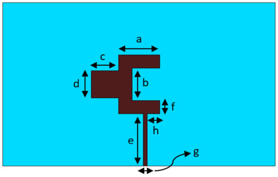
Geometry of the proposed antenna element used in the antenna arrays.
Table 1.
Dimensions of the antenna parameters.
| a | 1.5 mm | f | 0.5 mm |
| b | 1.2 mm | g | 0.15 mm |
| c | 1.0 mm | h | 0.46 mm |
| d | 1.0 mm | – | – |
| e | 1.9 mm | – | – |
The proposed antenna was used to implement an 8 × 8 antenna array, shown in Fig. 2, which consist of 16 interconnected antennas using power dividers. The array is excited though a 50-Ω feed network. In the design the distance between the radiating elements was made a multiple of 0.5λ to mitigate mutual coupling among the radiating elements. The spacing between the elements is optimized to obtain the best results. The length of the feedlines is made such that there is phase coherency and power equity at the individual antennas. This is important for preventing the erosion of the gain and radiation characteristics of the array. The dimensions of the other parameters annotated in Fig. 2 are given in Table 2. The overall size of the 8 × 8 array is 25.5 × 27.5 mm2.
Figure 2.
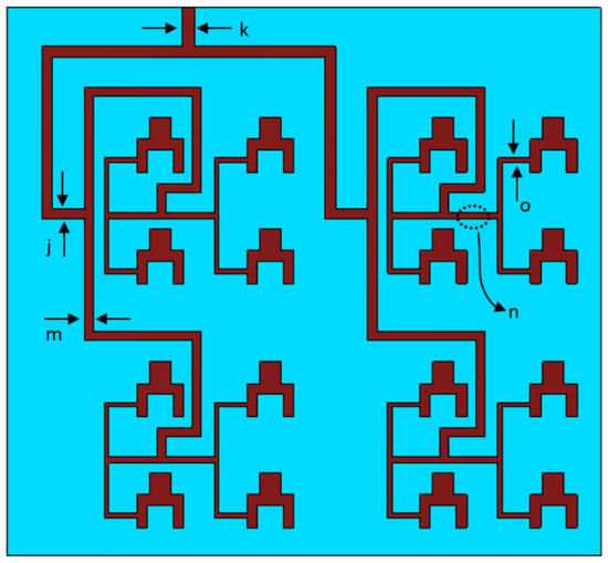
Geometry of the proposed 8 × 8 antenna array.
Table 2.
Dimensions of the proposed 8 × 8 and 8 × 16 antenna parameters.
| k | 0.6 mm | p | 0.7 mm |
| j | 0.5 mm | g | 0.15 mm |
| m | 0.41 mm | h | 0.46 mm |
| n | 0.3 mm | – | – |
| o | 0.19 mm | – | – |
The 8 × 8 array was extended to 8 × 16 array, which consisted of 32 antenna elements. This was achieved by using a power divider to split the input signal into two equal phase output signals that are applied to the two 8 × 8 array, as shown in Fig. 3a. The overall size of the 8 × 16 array is 27.5 × 55 mm2. The dimensions of the 8 × 8 array is given in Table 2. Again, it was important to ensure the length of the feedlines is made such that there is phase coherency and power parity at the individual antennas constituting the 32-element array. A quarter-wave transformer is used with the power divider to ensure impedance matching at the input.
Figure 3.
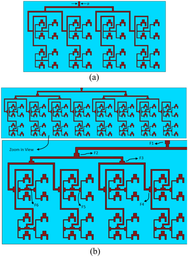
Geometry of the proposed antenna array, (a) 8 × 16, and (b) 8 × 32.
The 8 × 16 array was extended to 8 × 32 array using the above principles, as shown in Fig. 3b. The overall size of the array is 30 × 110 mm2. The dimensions of the F-parameters annotated in Fig. 3b are given in Table 3.
Table 3.
Dimensions of the F parameters in the 8 × 32 antenna array.
| Parameter | Length (mm) |
Width (mm) |
|---|---|---|
| F1 | 1 | 1.4 |
| F2 | 1 | 1.5 |
| F3 | 0.5 | 1.5 |
| F4 | 0.5 | 1.5 |
| F5 | 0.5 | 1.1 |
| F6 | 0.4 | 1.4 |
Results and discussion
Scattering parameter
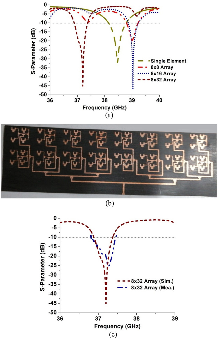
The simulated reflection coefficient of the single element antenna and the three antenna arrays, i.e., 8 × 8, 8 × 16 and 8 × 32, are shown in Fig. 4a. The single element antenna resonates at approximately 38.5 GHz with a reflection coefficient better than − 30 dB. The single element was used to construct the three arrays of increasing matrix size. Figure 4a shows the 8 × 8 array to resonate at 39 GHz with a reflection coefficient of − 20 dB, which is a reduction of nearly 10 dB compared to the single element antenna. The 8 × 16 array however has a significantly improved reflection coefficient of − 47 dB and it resonates at 39.1 GHz. This indicates excellent impedance matching. The 8 × 32 array too has a very good reflection coefficient of − 45 dB and it resonates at 37.2 GHz. In terms of footprint size, the 8 × 8 array occupies an area of 25.5 × 27.5 mm2 however this increases to 30 × 110 mm2 for a 8 × 32 array. The 8 × 32 operates at the 5G mm-Wave band. The fabricated prototype of the 8 × 32 array is shown in Fig. 4b. The measured reflection coefficient of the 8 × 32 array is shown in Fig. 4c. The measured result is in good agreement with the simulated one in terms of resonant frequency however the reduction in the reflection coefficient is attributed to unaccounted conductor loss, dielectric loss, and radiation loss. It should be noted that the conductivity of the metal, the skin effect, and surface roughness affect conductor losses in microstrip lines.
Figure 4.
Reflection coefficient comparison of the three antenna array designs, (a) simulated, (b) photograph of the fabricated 8 × 32 array, and (c) measured results of the 8 × 32 array.
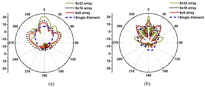
The radiation patterns of the proposed antenna and the three arrays of different matrix size using the antenn are compared in Fig. 5. The gain of single element antenna is 7.6 dBi. This gain is acceptable for a mobile handset but is not enough for 5G mm-Wave base stations that need to overcome signal attenuation resulting from path loss, multipath effects and atmoshoeric absorption. Figure 5 shows 8 × 8 array has a gain of 13 dBi however its side lobes are only less than − 6 dB in the phi = 0 degree plane however in the phi = 90 degree plane it is less than − 3 dB. This is not good as the system is prone to interference. In the case of the 8 × 16 array, it provides a gain of 15.3 dBi, which is acceptable for base stations however its side lobes too are less than − 6 dB in the phi = 0 degree plane and less than − 4 dB in the phi = 90 degree plane. In the case of the 8 × 32 array, it provides a substantial gain of 21.2 dBi and its side lobes are less than − 10 dB in the phi = 0 degree plane and less than − 12 dB in the phi = 90 degree plane, which is acceptable for practical applications. From Fig. 5 we can determine the angular width of the antenna in the phi = 90 degree plane. For the single antenna element the angular width is 82.5 degrees, for 8 × 8 array it is 18.4 degrees, for 8 × 16 array it is 7.2 degrees, and for 8 × 32 array it is 4.1 degrees. As expected the radiation beam becomes narrow and directed with increasing array size. The main purpose of this study was to verify the feasibility of the proposed antenna in arrays. However, further works is required to reduce the side lobes and to create a dual polarized array.
Figure 5.
Polar radiation patterns of the single antenna element and the three arrays (8 × 8, 8 × 16, and 8 × 32), (a) phi = 0 degree plane, and (b) phi = 90 degree plane.
Comparison with recent work
Over recent years numerous mm-wave antenna array designs have been investigated. Table 4 shows comparison of the proposed antenna array with recently reported works. In21 a dual band 5G multiple input multiple output (MIMO) antenna is reported that operates at 28 GHz and 38 GHz. The sub-array in21 consists of four gap-coupled microstrip slotted dual band patch antennas with corporate microstrip feed network. This sub-array exhibits a realized gain of 12 dBi at 28 GHz and 13 dB at 38 GHz. The antenna array in22 is based on stacked square ring patch arrangement. This antenna has a sharp roll-off and a filter like response between the operating bands due to the strongly coupled resonators. The antenna operates from 24.25 to 29.5 GHz and 37 to 40 GHz. This antenna array has a realized gain of between 5 and 6 dBi. In23 the authors have created an antenna array by stacking multiple split-ring resonators that interact with each other via aperture coupling. This antenna array operates from 24.25 to 29.5 GHz and has a realized gain between 5 to 6 dBi.
Table 4.
Comparison of the proposed antenna array with recent works.
| Refs | No. of elements | Center Freq. (GHz) | Gain (dBi) | Substrate permittivity (εr) | Dimensions (mm) |
|---|---|---|---|---|---|
| 23 | 1 × 2 | 26.87 | ~ 5–6 | 3.35 | 5 × 5 |
| 22 | 1 × 4 | 26.87 | ~ 5–6 | 3.35 | 5 × 5 |
| 22 | 1 × 4 | 38.5 | ~ 5–6 | 3.35 | 5 × 5 |
| 27 | 1 × 8 | 33.5 | 14.10 | 2.2 | 58 × 5.5 |
| 28 | 1 × 8 | 36 | 16.90 | 2.2 | 50 × 40 |
| 24 | 2 × 2 | 37 | 12.80 | 2.2 | 20 × 8 |
| 25 | 2 × 2 | 29 | 14.03 | 2.2 | 9.7 × 9.7 |
| 21 | 4 × 3 | 28 | 12.60 | 2.2 | 122 × 156 |
| 21 | 4 × 3 | 38 | 13 | 2.2 | 122 × 156 |
| 26 | 4 × 4 | 30.1 | 11.35 | 2.94 | 90 × 54 |
| 29 | 8 × 8 | 26 | 23.96 | – | – |
| 30 | 8 × 8 | 39 | 22 | 3.3 | 100 × 90 |
| 31 | 8 × 8 | 28 | 22 | 2.55 | 100.6 × 96.2 |
| 32 | 8 × 32 | 35 | 25.70 | 2.22 | 212 × 56 |
| This work | 8 × 32 | 37.2 | 21.20 | 2.20 | 110 × 30 |
The MIMO antenna array in24 consists of a two-antenna array combination where each antenna array consists of four elements which are arranged orthogonally with respect to each other. The antenna array has a gain of 12.8 dBi at 37 GHz. The 29 GHz magneto electric (ME) dipole array in26 is realized by the method of connecting and cutting patches. In27 a printed ridge gap waveguide 4 × 4 Butler matrix is shown to operate over the frequency range from 26.9 to 33.3 GHz with gain variation from 10.2 to 11.35 dBi. The array element in the broadband end-fire antenna in28 consists of a horizontally oriented printed electric dipole and a vertically aligned tapered slot radiator, where the two orthogonal radiated electric-field components are excited simultaneously. A parasitic director is introduced near the printed dipole to compensate for the gain degradation of the dipole element at higher frequencies.
In29 the 8 × 8 antenna array consists of a block of metallic array antenna sitting directly on the top surface of a printed circuit board (pcb) with electrical connections between them. The metallic array antenna is a metallic structure with 64 units of antenna radiating elements surrounded by a ring of metallic wall. The pcb provides the feeding mechanism for all 64 units of antenna radiating elements on the metallic array antenna. This antenna has a gain of 23.95 dBi at 26 GHz. The 8 × 8 element antenna array reported in30 uses a stacked multilayered pcb. It uses 16 commercial quad-core transmitter and receiver integrated circuits to independently control the phase and amplitude at each radiating element. The array designed at 39 GHz frequency band has a gain of 22 dBi. Reported in31 is an 8 × 8 aperture-coupled microstrip patch antenna array. It constructed from two substrate layers that are separated with an air gap. The patch antenna on the top layer is excited through a ground slot implemented on the top of the bottom substrate layer with a feedline on the bottom layer. This array is designed to operate over the 22–27 GHz frequency band with 22 dBi gain.
The work reported on 8 × 32 patch antenna arrays is scarce however the authors managed to find one paper32. The 8 × 32 antenna array in32 consists of a square patch antenna designed to operate at 35 GHz. The antenna array is reported to have a gain of 25.7 dBi. Although the gain in32 is higher than the proposed 8 × 32 antenna array however it has a much larger size by a factor of 3.6.
Conclusion
Results presented in the paper show the feasibility of a novel patch antenna configuration in the design of high-gain antenna arrays for application in future 5G mm-Wave base stations. The gain provided by the proposed singular antenna is 7.6 dBi. Although, this gain is suitable for mobile communication devices but it is not sufficient to overcome path loss and atmospheric loss experienced my millimeter wave signals at the 5G base station. Hence, a 64-element array antenna was implemented using the proposed antenna. This antenna array is shown to have a bore side gain of 21.2 dBi at 37.2 GHz, an angular width of 4.1 degrees and side lobe levels less than − 10 dB. This antenna has a significantly smaller form factor than 8 × 32 antenna array reported to date.
Declaration
All of the figures, materials, and data within the manuscript are original and owned by authors.
Acknowledgements
Dr. Mohammad Alibakhshikenari acknowledges support from the CONEX-Plus programme funded by Universidad Carlos III de Madrid and the European Union's Horizon 2020 research and innovation programme under the Marie Sklodowska-Curie grant agreement No. 801538. In addition, this work was partially supported by Ministerio de Ciencia, Innovación y Universidades, Gobierno de España (Agencia Estatal de Investigación, Fondo Europeo de Desarrollo Regional -FEDER-, European Union) under the research grant PID2021-127409OB-C31 CONDOR. The authors also sincerely appreciate funding from Researchers Supporting Project number (RSP2023R58), King Saud University, Riyadh, Saudi Arabia.
Author contributions
Conceptualization, D.A.S., J.K., M.A., M.AS., M.AB., B.V., W.A.S., S.K., M.I., S.J., A.U., F.F.; methodology, D.A.S., J.K., M.A., M.AS., M.AB., B.V., W.A.S., S.K., M.I., S.J., A.U., F.F.; software, D.A.S., J.K., M.A.; validation, D.A.S., J.K., M.A., M.AS., M.AB., B.V., W.A.S., S.K., M.I., S.J., A.U., F.F.; formal analysis, D.A.S., J.K., M.A., M.AS., M.AB., B.V., W.A.S., S.K., M.I., S.J., A.U., F.F.; investigation, D.A.S., J.K., M.A., M.AS., M.AB., B.V., W.A.S., S.K., M.I., S.J., A.U., F.F.; resources, D.A.S., J.K., M.A., M.AS., W.A.S., S.K., M.I., S.J., A.U.; data curation, D.A.S., J.K., M.A., M.AS., W.A.S., M.I.; writing—original draft preparation, D.A.S.; writing—review and editing, D.A.S., J.K., M.A., M.AS., M.AB., B.V., W.A.S., S.K., M.I., S.J., A.U., F.F.; visualization, D.A.S., J.K., M.A., M.AS., M.AB., B.V., W.A.S., S.K., M.I., S.J., A.U., F.F.; supervision, M.AB., M.AS.; project administration, M.AB., B.V., F.F.; funding acquisition, M.AB., S.K., F.F.. All authors have read and agreed to the published version of the manuscript.
Data availability
All data generated or analyzed during this study are included in this article.
Competing interests
The authors declare no competing interests.
Footnotes
Publisher's note
Springer Nature remains neutral with regard to jurisdictional claims in published maps and institutional affiliations.
Contributor Information
Muhammad Asif, Email: masifeed@ustb.edu.pk, Email: mohammad.alibakhshikenari@uc3m.es, Email: francisco.falcone@unavarra.es.
Mohammad Alibakhshikenari, Email: masifeed@ustb.edu.pk, Email: mohammad.alibakhshikenari@uc3m.es, Email: francisco.falcone@unavarra.es.
Francisco Falcone, Email: masifeed@ustb.edu.pk, Email: mohammad.alibakhshikenari@uc3m.es, Email: francisco.falcone@unavarra.es.
References
- 1.Sehrai DA, Asif M, Shah WA, Khan J, Ullah I, Ibrar M, Jan S, Alibakhshikenari M, Falcone F, Limiti E. Metasurface based wideband MIMO antenna for 5G millimeter-wave systems. IEEE Access. 2021;9:125348–125357. doi: 10.1109/ACCESS.2021.3110905. [DOI] [Google Scholar]
- 2.E.C. Strinati, S. Barbarossa, J. L. Gonzalez-Jimenez, D. Kténas, N. Cassiau, L. Maret, and C. Dehos, “6G: THE NEXT FRONTIERFrom Holographic Messaging to Artificial Intelligence Using Subterahertz and Visible Light Communication,” IEEE Vehicular Technology Magazine, 2019, pp. 42–50.
- 3.Zhang J, Huang Y, Wang J, Schober R, Yang L. Power-efficient beam designs for millimeter wave communication systems. IEEE Trans. Wireless Commun. 2020;19(2):1265–1279. doi: 10.1109/TWC.2019.2952340. [DOI] [Google Scholar]
- 4.Xu H, Yu J, Zhu S. Ping-pong optimization of user selection and beam allocation for millimeter wave communications. IEEE Access. 2019;7:133178–133189. doi: 10.1109/ACCESS.2019.2941261. [DOI] [Google Scholar]
- 5.Sharaf MH, Zaki AI, Hamad RK, Omar MMM. A novel dual-band (38/60 GHz) patch antenna for 5G mobile handsets. Sensors. 2020;20:2541. doi: 10.3390/s20092541. [DOI] [PMC free article] [PubMed] [Google Scholar]
- 6.Hussain N, Jeong M-J, Abbas A, Kim N. Metasurface-based single-layer wideband circularly polarized MIMO antenna for 5G millimeter-wave systems. IEEE Access. 2020;8:130293–130304. doi: 10.1109/ACCESS.2020.3009380. [DOI] [Google Scholar]
- 7.Tariq S, Naqvi SI, Hussain N, Amin Y. A metasurface-based MIMO antenna for 5G millimeter-wave applications. IEEE Access. 2021;9:51805–51817. doi: 10.1109/ACCESS.2021.3069185. [DOI] [Google Scholar]
- 8.S. Vij and A. Jain. 5G: Evolution of a Secure Mobile Technology, 3rd International Conference on Computing for Sustainable Global Development (INDIACom), 2016, pp. 2192–2196.
- 9.Barreto AN, Faria B, Almeida E, Rodriguez I, Lauridsen M, Amorim R, Vieira R. 5G-wireless communications for 2020. J. Commun. Inform. Syst. 2016;31:146–163. [Google Scholar]
- 10.Storck CR, Duarte-Figueiredo F. A survey of 5G technology evolution, standards, and infrastructure associated with vehicle-to-everything communications by internet of vehicles. IEEE Access. 2020;8:117593–117614. doi: 10.1109/ACCESS.2020.3004779. [DOI] [Google Scholar]
- 11.M.A.B. Abbasi and Q.H. Abbasi, “Development Challenges of Millimeter‐Wave 5G Beamformers,” Wiley 5G Ref. Wiley, 2020, pp. 1–22.
- 12.Khan J, Sehrai DA, Ali U. Design of dual band 5G antenna array with SAR analysis for future mobile handsets. J. Electr. Eng. Technol. 2019;14:809–816. doi: 10.1007/s42835-018-00059-9. [DOI] [Google Scholar]
- 13.M. Peng, A, Zhao, “High Performance 5G Millimeter-Wave Antenna Array for 37–40 GHz Mobile Application,” Proceedings of the IEEE International Workshop on Antenna Technology (iWAT), Bucharest, Romania, 25–28 February 2018, pp. 1–4.
- 14.J. Park, D. Choi, W, Hong, “37–39 GHz Vertically-Polarized End-Fire 5G Antenna Array Featuring Electrically Small Profile,” Proceedings of the IEEE International Symposium on Antennas and Propagation & USNC/URSI National Radio Science Meeting, Marina Bay Sands, Singapore, 2018, pp. 637–638.
- 15.Yuan Y, Sun S, Chen Y, Zhang K, Ding X, Ratni B, Qun Wu. Shah Nawaz Burokur, Cheng-Wei Qiu, A fully phase-modulated metasurface as an energy-controllable circular polarization router. Adv. Sci. 2020;7(18):2001437. doi: 10.1002/advs.202001437. [DOI] [PMC free article] [PubMed] [Google Scholar]
- 16.Zhang K, Wang Y, Burokur SN, Wu Q. Generating dual-polarized vortex beam by detour phase: from phase gradient metasurfaces to metagratings. IEEE Trans. Microw. Theory Tech. 2022;70(1):200–209. doi: 10.1109/TMTT.2021.3075251. [DOI] [Google Scholar]
- 17.Wang Y, Yuan Y, Yang G, Ding X, Wu Q, Jiang Y, Burokur SN, Zhang K. Perfect control of diffraction patterns with phase-gradient metasurfaces. ACS Appl. Mater. Interfaces. 2022;14(14):16856–16865. doi: 10.1021/acsami.2c00742. [DOI] [PubMed] [Google Scholar]
- 18.Khan J, Sehrai DA, Khan MA, Khan HA, Ahmad S, Ali A, Arif A, Memon AA, Khan S. Design and performance comparison of rotated Y-shaped antenna using different metamaterial surfaces for 5G mobile devices. Comput. Mater. Contin. 2019;2:409–420. [Google Scholar]
- 19.Nosrati M, Tavassolian N. A single feed dual-band, linearly/circularly polarized cross-slot millimeter-wave antenna for future 5G networks. Proceedings of the IEEE International Symposium on Antennas and Propagation & USNC/URSI National Radio Science Meeting, Denver, CO, USA. 2017;10–15:2467–2468. [Google Scholar]
- 20.Sehrai DA, Asif M, Shoaib N, Ibrar M, Jan S, Alibakhshikenari M, Lalbakhsh A, Limiti E. Compact quad-element high-isolation wideband MIMO antenna for mm-wave applications. Electronics. 2021;10:1300. doi: 10.3390/electronics10111300. [DOI] [Google Scholar]
- 21.T. Elhabbash and T. Skaik, “Design of Dual-band Dual-polarized MIMO Antenna for mm-wave 5G Base Stations with Octagonal Prism Structure,” IEEE 7th Palestinian International Conference on Electrical and Computer Engineering (PICECE), 2019, pp. 1–6.
- 22.Z. Siddiqui, M. Sonkki, J. Chen, M. Berg, M. E. Leinonen and A. Pärssinen, “Dual-band Dual-polarized Antenna for mm-Wave 5G Base Station Antenna Array,” 14th European Conference on Antennas and Propagation (EuCAP), 2020, pp. 1–4.
- 23.Z. Siddiqui et al., “Dual-Polarized Filtering Antenna for mm-Wave 5G Base Station Antenna Array,” 15th European Conference on Antennas and Propagation (EuCAP), 2021, pp. 1–4.
- 24.Khan J, Ullah S, Ali U, Tahir FA, Peter I, et al. Design of a millimeter-wave MIMO antenna array for 5G communication terminals. Sensors. 2022;22:2768. doi: 10.3390/s22072768. [DOI] [PMC free article] [PubMed] [Google Scholar]
- 25.K.-X. Li, Y.-W. Wu, Z.-C. Hao, “A 5G Millimeter-Wave Circularly Polarized Planar Antenna Array,” 9th Asia-Pacific Conference on Antennas and Propagation (APCAP), 2020, pp.1–2.
- 26.Afifi A, Sebak A-R. Wideband 4×4 butler matrix in the printed ridge gap waveguide technology for millimeter-wave applications. IEEE Trans. Antennas Propag. 2020;68(11):7670–7675. doi: 10.1109/TAP.2020.2981716. [DOI] [Google Scholar]
- 27.Yu Y, Jiang ZH, Zhang J-D, Wu W. Broadband millimeter-wave endfire circularly polarized array with a low-profile feeding structure. IEEE Trans. Ant. Propag. 2022;70(8):7270–7275. doi: 10.1109/TAP.2022.3164895. [DOI] [Google Scholar]
- 28.Li A, Luk K-M. Millimeter-wave end-fire magneto-electric dipole antenna and arrays with asymmetrical substrate integrated coaxial line feed. IEEE Open J. Ant. Propag. 2021;2:62–71. doi: 10.1109/OJAP.2020.3044437. [DOI] [Google Scholar]
- 29.Y. C. M. Tan and N. Guan Hong, “64-Elements mmWave Detachable Phased Array Antenna for 5G 26GHz Band,” 2020 IEEE International Symposium on Antennas and Propagation and North American Radio Science Meeting, 2020, pp. 1317–1318.
- 30.R. Valkonen, E. Doumanis, “Analysis and Design of Mm-Wave Phased Array Antennas for 5G Access,” IEEE Int. Symposium on Antennas and Propagation and USNC-URSI Radio Science Meeting, 2019, pp. 611–612.
- 31.Islam MA, Karmakar NC. An 8×8 mm-wave LP ACMPA array for a long-range mm-wave chipless RFID tag-sensor reader. IEEE J. Radio Frequen. Identif. 2021;5(1):53–63. doi: 10.1109/JRFID.2020.3036721. [DOI] [Google Scholar]
- 32.Verma PK, Kumar R, Singh VK, Kumar A. Dual radiator based low profile fan beam antenna for millimeter wave fencing system. Int. J. Adv. Microw. Technol. 2021;6(1):254–259. doi: 10.32452/IJAMT.2021.254259. [DOI] [Google Scholar]
Associated Data
This section collects any data citations, data availability statements, or supplementary materials included in this article.
Data Availability Statement
All data generated or analyzed during this study are included in this article.


