

Abstract
Studies of electrosensory systems have led to insights into to a number of general issues in biology. However, investigations of these systems have been limited by the inability to precisely control spatial patterns of electrosensory input. In this paper, an electrode array and a system to selectively stimulate spatially restricted regions of an electroreceptor array is presented. The array has 96 channels consisting of chrome/gold electrodes patterned on a flexible parylene-C substrate and encapsulated with another parylene-C layer. The conformability of the electrode array allows for optimal current driving and surface interface conditions. Recordings of neural activity at the first central processing stage in weakly electric mormyrid fish support the potential of this system for high spatial resolution stimulation and mapping of electrosensory systems.
Keywords: electrode array, flexible, electric fish, stimulation, neurophysiology
Graphical Abstract

This work presents a flexible, conformal and dense electrode array and electronic system capable of stimulation of electrosensory systems through activation of different individual terminal sites on an electrode array. In-vivo neural recordings at the first central processing stage showed its capability to drive graded and spatially specific neuronal responses in a weakly electric mormyrid fish.
1. Introduction
Many aquatic animals possess electroreceptors on their body surface that allow them to detect weak electrical fields in the environment.[1] A smaller number of so-called “electric fish” are capable of both sensing and generating electrical fields.[2] The emitted fields, known as electric organ discharges (EODs), are used to sense objects in the nearby environment, communicate with other electroreceptive species, and in the case of strongly electric species such as the South American electric eels, to immobilize prey. Studies of electrosensory and electromotor systems have shed light on a wide range of issues in neuroscience, evolutionary biology, and ecology as well as providing inspiration for the development of artificial sensors and robotics systems.[3–5]
Although the early stages of electrosensory processing have been extensively studied in a number of species, the lack of convenient methods to control spatial patterns of electrosensory input has been a persistent limitation. The typical approach for controlled electrosensory stimulation involves passing current through a dipole electrode in one of a small number of configurations: locally via two closely-spaced electrodes positioned directly adjacent to electroreceptors on the skin or globally via two distant electrodes positioned near the head and tail of the fish or transversely on either side of the fish. The local configuration is typically intended to mimic a conducting object or external current source near the fish while the global configuration mimics the fish’s own EODs or those of other fish. Though such stimuli have generated useful results, they are inadequate for studying more sophisticated aspects of electroreception. For example, behavioral studies have demonstrated that weakly electric fish are capable of discriminating the distance, size, and shape of objects based solely on electrolocation.[6]
While some attempts at developing approaches for controlling spatial patterns of electrosensory have been made, none are in common use to our knowledge. One study used a rigid, sparse 1-D array of electrodes (vertical stripes) together with an electrostatic model to compute electrode voltages required to produce a desired spatial pattern of stimulation on the body surface. However, because the sensory surface (electroreceptors on the skin) is typically curved and irregular, estimating key parameters of the model, such as the distance of electrodes from the skin was difficult. Because of the steep fall-off of electrical field in water and the exquisite sensitivity of electroreceptors to small voltage differences, time-consuming calibration procedures were required to achieve adequate results.[7]
Here we report on the development of a flexible, dense, 2-D electrode array for studies of electrosensory systems. By conforming to the fish’s skin, the array greatly simplifies the problem of delivering spatial patterns of electrosensory stimulation. The design presented in this paper stems from the many flexible sensing electrode arrays that have been demonstrated in the past. Flexible electrode arrays have been used to replace rigid penetrating microelectrode arrays that damage brain tissue upon insertion.[8–15] In particular, Jeong et al. (2016) demonstrated the advantages of using a parylene-caulked polydimethylsiloxane (PDMS) substrate for neural electrodes in terms of impedance stability, stretchability, and water absorption rate.[11] Viventi et al. (2011) demonstrated an actively multiplexed highly-dense electrode array for mapping in vivo brain activity using flexible silicon technology.[13] Meacham et al. (2008) demonstrated a multi-electrode array for surface stimulation of a rat spine by patterning gold between micropatterned PDMS.[12] Although it is rather common to use electrode arrays for sensing neural responses as shown in above-mentioned works, none of the previous electrode arrays were used for delivering spatial patterns of electrosensory stimulation to our knowledge as is demonstrated in this manuscript. Different parameters of the electrode array such as the electrode size to match the size of the electroreceptor sites, the spatial frequency to match the pitch of the electroreceptor sites were optimized for this specific application.
In addition to array substrate and fabrication optimization, it is key that the array is stable and weakly bonded to the surface when placed on the electric fish. Stable surface modifications for silicone and polymer materials have been investigated to optimize the surface interface between arrays and biological tissues.[16] Treatment of PDMS based electrode array with 2- Hydroxyethyl-methacrylate (HEMA) to match the surface energy of the array to that of the fish for better adhesion is discussed.
2. Electrode Array
Electroreceptor stimulation is provided by an electrode array whose flexible substrate conforms to the curvature of the receptor surface. Here we apply the array to the dorsal trunk of an ~12 cm fish of the species Gnathonemus petersii, however, direct application to a wide range of fish species should be possible. Two separate electrode arrays were fabricated, one on a PDMS/parylene stack as a substrate and a second, where only parylene is used as a substrate material. PDMS being less flexible and less conformable than parylene, provides good mechanical support but demonstrates poor adhesion to the surface of the fish. Meanwhile, parylene is more flexible but less durable. It is able to weakly bond to the surface of the fish offering better conformability. Hence parylene is used as the substrate material for final experiments. The electrode array contains 96 square chrome/gold electrodes in a hexagonal pattern with a side length of 250 μm and diagonal spacing of 1 mm as shown in Figure 1a. This pattern was designed to be evenly distributed across the electroreceptor area with an electrode density approximately equal to that of the electroreceptors. In the future, a denser layout would allow for isolated stimulation of individual electroreceptors. The chrome/gold electrodes were photolithographically patterned on parylene. A second layer of parylene was deposited and patterned for encapsulation to eliminate crosstalk between electrodes. Silane is used to ensure good adhesion between the substrate layer parylene and encapsulation layer parylene. This step prevents water from reaching in between the layers, which could provide leakage current pathways.[17] The reduction or elimination of leakage pathways ensures the stimulation at one electrode sites would be localized as desired. A microscopic image of the patterned electrode is shown in Figure 1c. The detailed fabrication steps are mentioned in the experimental section. The electrode array substrate must remain flexible to ensure conformability on any curved surface. We test the conformability of the fabricated array by placing it on a circular object as shown in Figure 1e. Finally, Figure 1f shows the electrode array placed on the dorsal surface of the trunk where it conforms with the curvature of the body. The individual electrodes (filled arrow) and electroreceptors (open arrow) beneath the array are visible in the expanded view.
Figure 1.

(a) Electrode array design with 96 square electrodes leading to connector pads. (b) Zoomed in version of the array showing electrodes spacing of 1 mm. (c) Microscopic image of the patterned electrode array and the metal (Cr/Au) traces. (d) Zoomed in electrode array showing parylene encapsulating electrode edges and traces. (e) Electrode array placed on a circular object showing the parylene-C substrate’s flexibility and conformability (f) Electrode array placed on the dorsal side of the mormyrid fish. Electroreceptors are visible beneath array.
To explore the adhesion between the electrode array with a PDMS substrate and fish skin, contact angle measurements were performed on mormyrid fish skin, parylene, and thin film gold on parylene/PDMS to characterize their surface energy. The surface energy of each sample was calculated from contact angle measurement using the Owens/Wendt theory for polymers.[18,19] As shown in Figure 2, the measured surface energy of the fish skin is 81 +/− 2 mN/m. Parylene has a lower surface energy of 41 +/− 1 mN/m. To better match the surface energy of the fish skin, a self-assembled monolayer surface treatment was performed on the electrode array. The focus was to change the surface energy of the parylene since parylene is the top layer for the majority of the array. The results demonstrate that exposing the surface to UV/ozone then spin-coating the surface with 2- Hydroxyethyl-methacrylate (HEMA) altered the surface energy to match that of the fish. HEMA was chosen for its hydrophilic bonds and low toxicity.[20] The contact angle values measured and respective sum of dispersive and polar surface energies calculated using the Owens / Wendt Theory agree with those cited in literature.[19,21,22]
Figure 2.

Surface energy of parylene-C compared with Mormyrid fish (Gnathonemus petersii) for different surface treatment conditions. Increase in surface energy of ozone/HEMA treated parylene is observed compared to only UV/ozone treated parylene.
2.1. Electrical Characterization
Another important benchmark for the array is the ability to supply constant current that spreads sufficiently in water to activate electroreceptors since most electrodes will not be in direct physical contact with electroreceptors. To experimentally validate the current drop-off and spreading throughout the water, a constant current was supplied between a platinum wire and thin film metal electrodes of platinum, gold, and aluminum. The wire and electrodes were placed in the water used for mormyrid fish neurophysiological experiments (conductivity of 71 μS). This setup to characterize the current drop-off is shown in Figure 3a. The voltage between these electrodes and the platinum wire was then measured at various distances. The metal electrodes have the same thickness and substrate material (Parylene-C) as the metal used in the electrode array but increased in size from the original array. The size of the electrodes used in this measurement was 10mm x10mm while the size of the electrodes in the original array was 250µm x 250µm. The increased size of the electrode array reduces the interface impedance of the electrode by increasing the double layer capacitance with the increased area. Thus, the series impedance in this measurement is dominated by the spread/access resistance of the solution. This change was also made for ease of testing apart from reducing the impact of the interface impedance.
Figure 3.
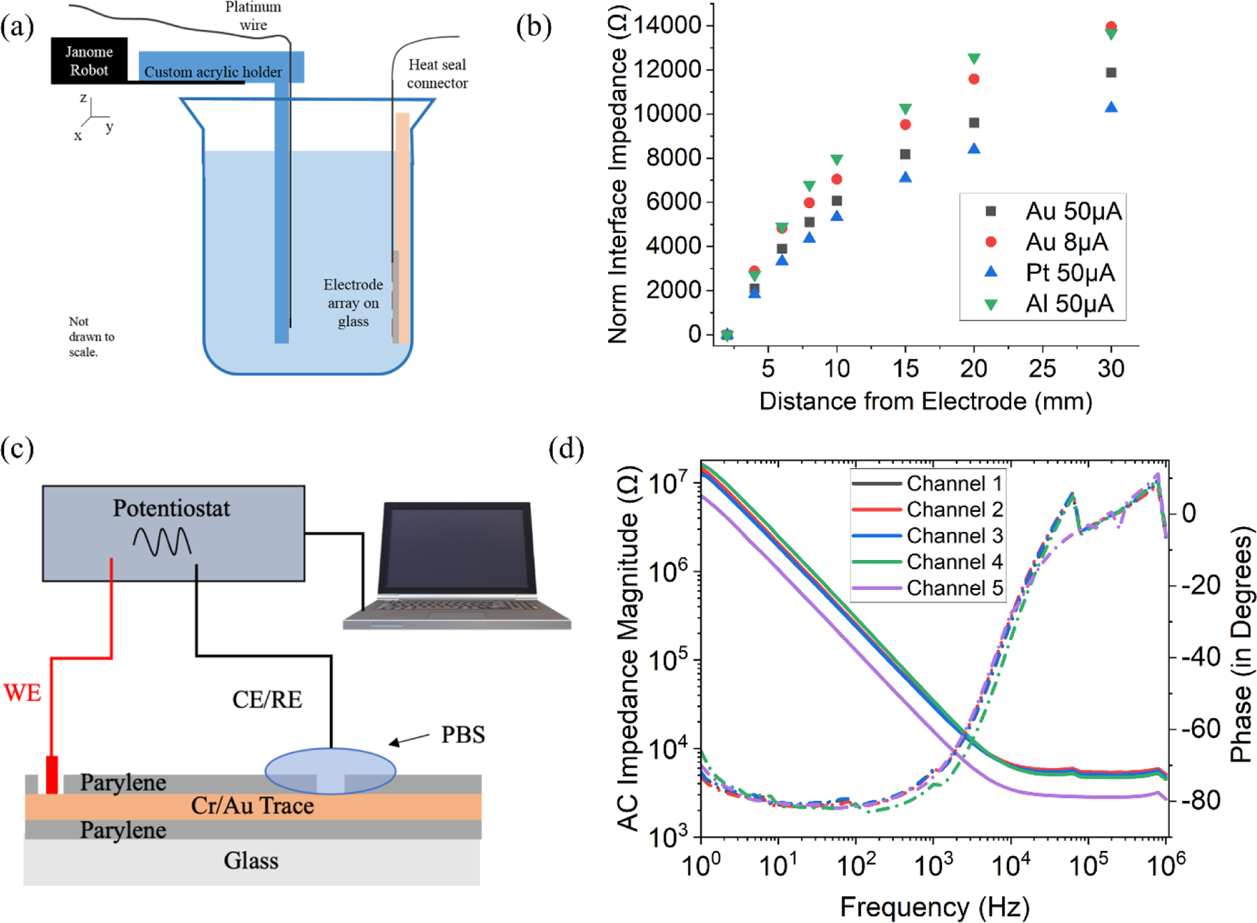
(a) Current drop-off measurement setup (b) Plot showing increase in the impedance of metal-water interface with increased distance from various metal electrodes (c) Electrochemical Impedance Spectroscopy (EIS) measurement setup (d) EIS impedance and phase plot as a function of frequency.
As expected, the measured impedance of the water in this experiment increases nonlinearly with distance due to secondary material and electronic effects as shown in Figure 3b. We found that platinum is a slightly better electrode material in this test due to its superior ability to ionize water; however, the ease of fabricating electrodes of chrome/gold rather than platinum outweighed this advantage when deciding on a material for the final test array.
In addition to the current drop off measurement, it is critical to understand the interface characteristics of the electrode and the electrolyte. A standard way to electrically characterize an electrode-electrolyte interface is through electrochemical impedance spectroscopy (EIS).[23–26] The two-electrode setup consisting of working electrode (WE) and counter electrode (CE)/reference electrode (RE) to perform EIS measurement is shown in Figure 3c. The working electrode is connected to the soldering pad of the array and reference electrode is dipped into phosphate buffered solution (PBS) solution which covers the electrodes. A Potentiostat is used to apply a voltage of 10mV at a range of frequencies and measure the current between the working and reference electrodes. The current measured and the applied voltage is used to obtain the interface impedance. Traditionally, the electrode impedance is reported at 1 kHz for a standard comparison[27,28]. The EIS impedance magnitude and phase plot is shown in Figure 3d for five different randomly selected channels. The impedance between the electrode and electrolyte decreases with increasing frequency and the phase become less negative. This result indicates the capacitive nature of the interface impedance as observed in previous studies[29]. We showed an average impedance magnitude of 27.2 kΩ at 1kHz and phase of −73.16 degrees for 20 random channels indicating a typical gold interface[30,31]. The negative phase of less than −45 degrees indicates that the impedance is dominated by the capacitive nature of the gold electrode-PBS interface. The low impedance magnitude allows the current stimulus to be easily transferred to the electrolyte and create the spatial electric field pattern.
3. System Development and Integration
The system level diagram is shown in Figure 4. After fabrication, the electrode array is connected to the custom printed circuit board (PCB) using a flexible anisotropic heat seal connector through a hot bar bonding process. The PCB contains the multiplexers and driving electronics needed to select and drive current to all 96 electrodes. The specific PCB components are discussed in the supplementary section and its design is shown in Figure S2. A current source for providing the current stimulation is connected to the multiplexers channel. A pulsed current (0.1 ms; 5–50 µA) is delivered using the stimulus isolation unit (ISO-Flex, A.M.P.I., Israel). The multiplexers are programmed and controlled using an Arduino compatible Metro Mini microcontroller. The Arduino also provides a byte of digital outputs enumerating the electrode location to the digital marker channel in Spike2 (CED, England), which enables neurophysiological data acquisition to be synced with electrode addressing. The Arduino is controlled through a LabVIEW GUI for individual electrode selection. The LabVIEW user interface controlled the addressing of the multiplexers and serial communication
Figure 4.

(a) System level block diagram illustrating interconnection of various components
4. Neurophysiology Results
There are two main benchmarks in device performance that must be met before tailoring the use of the electronic array to specific neuroscience questions. First, the system must be capable of reliable and graded activation of electroreceptors. Second, terminal sites must be sufficiently isolated from one another to allow for spatially selective activation of small skin regions. We performed initial experiments to address these experiments by recording local field potentials (LFPs) in the electrosensory lobe (ELL). Past studies have shown that LFP amplitude faithfully reflects the strength of the electrical field on the skin.[33] In addition, the ELL is characterized by a strict somatotopic organization, i.e., nearby electroreceptors innervate neighboring regions of the ELL. LFPs faithfully reflect this somatotopy in that, for at any particular location within the ELL, LFPs can only be evoked from the corresponding region of the body surface.
LFPs were recorded from a single glass microelectrode positioned at a region of the ELL innervated by electroreceptors on the dorsal trunk. Recording location was verified using a standard local dipole stimulus prior to placement of the electrode array onto the skin surface over the dorsal trunk. Brief constant current pulses (0.1 ms) evoked prominent LFP responses that graded smoothly as a function of stimulus current amplitude as shown in Figure 5a. Current strengths were within a factor of 2–3 of those required to evoke responses with dipole electrodes placed in the water close to the skin. Although the current amplitudes required for evoking ELL field potential using the electrode array were comparable to those required for dipole stimuli (i.e. tens of microamps)[32], a direct comparison was not made. Such a comparison would require accounting for the exact distance between the electrode and the electroreceptors, which is not readily determined since the array adheres tightly to the skin, preventing visualization of the receptors. To test spatial selectivity, we collected responses for >50 trials at a fixed current intensity (−15µA) for each of the 96 electrodes. Most electrodes failed to evoke a response while those evoking responses were spatially clustered as shown in Figure 5c. Stimulation at most sites on the electrode array yielded no field potential response. This is expected due to the fact that we recorded from a single location on the ELL map. Each location on the map is responsive to stimulation of a very restricted portion of the receptor surface of the skin. Indeed, the spatial selectivity of the responses on the array provides strong support that activation is restricted to receptors in close proximity to the electrodes. Although these results clearly support the potential of the array for delivering spatially patterned stimuli, additional tests of multiple locations on the array across a range of intensities are needed to determine the degree of spatial selectivity that can be achieved.
Figure 5.
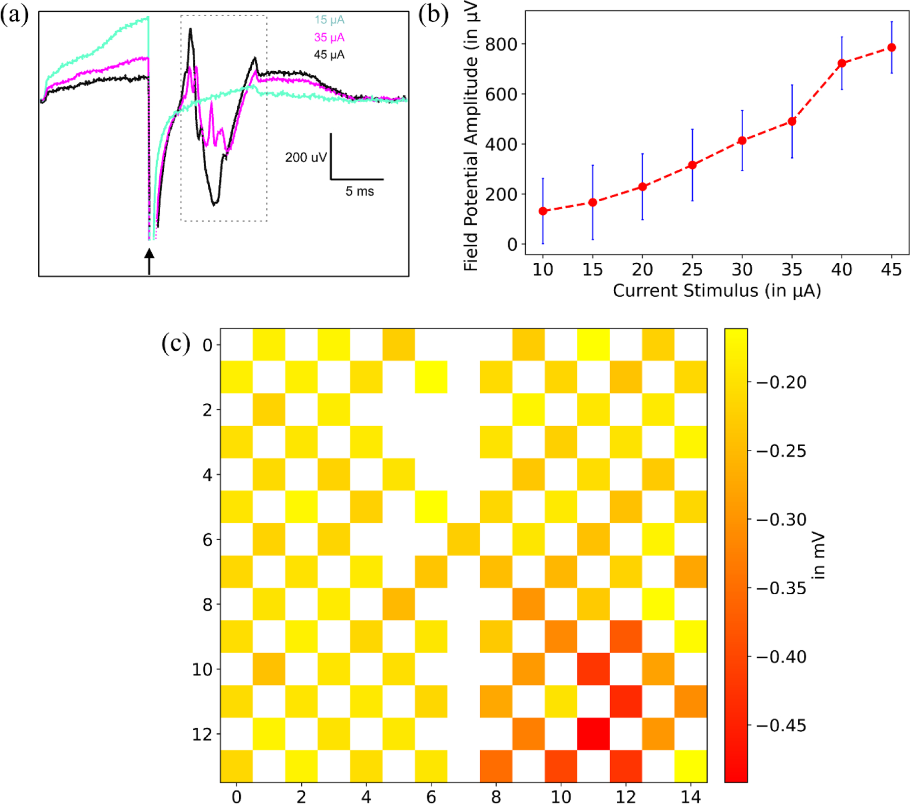
(a) Local field potential (LFP) responses in the granular layer of the electrosensory lobe evoked by stimulation at three different current intensities. Arrow indicates time of stimulus pulse. Neural responses (dashed box) an be clearly separated from the preceding electrical stimulation artifact. (b) LFP amplitude (the difference between the maximum negativity of the response and the baseline potential) increases with stimulus intensity. Error bars indicate standard deviation. Sensitivity and range of response are comparable to those obtained with dipole stimulation[32]. (c) Average local field potential (LFP) amplitude evoked by different stimulation locations on the electrode array. As expected, responses at a given site in the ELL are only evoked by stimulation of a restricted region of the skin surface, confirming the spatial specificity of the stimulation.
A surprising number of vertebrate species rely on electrolocation for foraging, navigation, and social behavior[1]. Moreover, behavioral studies of weakly electric fish have shown that the location, size, shape, and distance of objects can be determined based solely on electrosensory information[6,34]. However, in contrast to studies of vision for example, little is known about the neural basis for spatial processing of electrical images. The flexible electrode array described here provides a novel tool for probing spatial aspects of electrosensory processing that underlie these remarkable capabilities. The density of electroreceptors on the trunk of Gnathonemus petersii is ~1 per mm2[35]. With a modest increase in array size and density, the apparatus described here will allow for individual control over all of the electroreceptors on the dorsal trunk. Future apparatus designs will also include additional electronics and control allowing for simultaneous stimulation of multiple electrodes with specifiable spatial and temporal patterns. Combined with neural recordings, these added capabilities will allow for the first in depth investigations of spatial electrosensory processing.
5. Conclusion
A dense conformal electrode array with 96 channels and a system to individually drive each of the electrodes for current simulation was presented in this work. The electrode array was characterized using electrochemical impedance spectroscopy (EIS) and showed an average AC impedance magnitude of approximately 27 kΩ indicating a typical gold interface. Thin layers of parylene-C (~3um each) were used as a substrate and an encapsulation layer for conformal adhesion to the surface of the electric fish skin which is a key to a localized and repeatable stimulation of the electroreceptors. In vivo recordings showed that activation of different terminal sites on the electrode array could drive graded and spatially specific neuronal responses. Goals for further development include: (1) increasing the density of electrodes, which should allow for selective activation of individual electroreceptors and (2) adding hardware and software to enable simultaneous activation of multiple electrodes. The technology described here is expected to enable studies of a range of issues related to electrosensory systems, including the neural representation of complex spatial and temporal patterns of electrosensory input characteristic of natural environments. This setup could also be potentially used for high resolution stimulation in other electrosensory systems as well. Application of this system to other system would require re-optimization of the critical parameters such as the electrode size and the spatial frequency to match the species electroreceptor patterns.
6. Experimental Section
6.1. Array Fabrication
For ease of handling during the fabrication process, a 4” glass wafer is used as the carrier wafer. The glass is first cleaned by successive ten-minute sonication in 10% Micro 90, acetone, isopropyl alcohol (IPA) and DI water. It is then followed by UV-Ozone treatment for further cleaning. The surface is then silanized with trichloro(1H,1H,2H,2H-perfluorooctyl)silane by vacuum vaporization to ensure easy removal during post-processing. 3 μm of parylene-C is chemically vapor deposited on top of the glass substrate using SCS Labcoater Parylene Deposition System. Chrome (40 nm) / gold (120 nm) is then deposited by e-beam evaporation in a Angstrom Deposition System. The metal layers are then photolithographically patterned using S1811 photoresist to the desired electrode pattern before developing (AZ300MIF, IMM)) and wet etching in Gold Etch TFA and Chromium Etchant Type A (Transene). After the photoresist has been stripped with acetone, a second 3 μm-thick parylene-C layer is deposited to encapsulate the electrode traces. Parylene is photolithographically patterned to create opening for electrode and solder pads and the photoresist is used as an etch mask for etching the Parylene-C using oxygen plasm in an Oxford RIE etcher system. Finally, the array pads are hot bar bonded using heat seal connector (Elform) to a printed circuit board before the electrode array is peeled off of the glass substrate. The step-by-step fabrication process with schematic is shown in Figure S1.
6.2. Surface Modification
Samples with PDMS as substrate were exposed to UV/ozone for 5 minutes. They were then spin-coated with 2-Hydroxyethyl-methacrylate (HEMA) at 1500 rpm for 25 seconds. Contact angle measurements were taken immediately after the spin-coating process.
6.3. Surface Energy Calculation
Contact angle measurements were performed by placing 15 μL of deionized water and diiodomethane on fish skin and the electrode array sample to calculate polar and dispersive surface energy components, respectively. Owens and Wendt theory was used to calculate the surface energy components from the contact angle.
6.4. Electrode Characterization
Platinum wire was taped to a laser-cut piece of acrylic and insulated with Kapton tape. The wire and acrylic were attached to a 3D XYZ robot (Janome JR 2200N mini). A custom LabVIEW program was used to control the position of the robot[36]. A metal electrode on parylene/PDMS/glass was heat sealed to a custom PCB adapter and attached to a side of a beaker vertically so that the electrode was horizontally across from the platinum wire. The metal electrode PCB and platinum wire were connected to the positive and negative terminals of an Agilent Precision Source/Measure Unit (Model B2901A), which was used to source constant current and measure voltage.
6.5. User Interface for Experiments
A simple user interface is critical in this system due to the complexity of the electronic system and need for measurement repeatability. LabVIEW was chosen to control the system because it can easily be programmed to provide a straightforward user interface. The interface, shown in Figure. 4b, displays a spatially accurate map of the electrodes and the user can turn each one on by clicking the corresponding button. The LabVIEW file recognizes which electrode has been selected and transmits electrode information to an Arduino Metro Mini, which controls the multiplexer network used to send current to the chosen electrode. When the button is unselected, the Arduino will receive a code that indicates no electrode is selected and the current will no longer flow to the electrode array. This ON/OFF capability was necessary as varying the time electrodes were “on” was desired. Though currently integrated with Spike2, the custom script in LabView can be integrated with other neurophysiology platforms and adapted into a Python GUI, if needed in future cases.
6.6. Neural Recordings
Mormyrid fish (7–12 cm in length) of the species Gnathonemus petersii were used in these experiments. Fish were housed in 60-gallon tanks in groups of 5–20. Water conductivity was maintained between 40–65 µS both in the fish’s home tanks and during experiments. All experiments performed in this study adhere to the American Physiological Society’s Guiding Principles in the Care and Use of Animals and were approved by the Institutional Animal Care and Use Committee of Columbia University.
For surgery to expose the brain for recording, fish were anesthetized (MS:222, 1:25,000) and held against a foam pad. Skin on the dorsal surface of the head was removed and a long-lasting local anesthetic (0.75% Bupivacaine) was applied to the wound margins. A plastic rod was cemented to the anterior portion of the skull to secure the head. The posterior portion of the skull overlying the ELL was removed. Gallamine triethiodide (Flaxedil) was given at the end of the surgery (~20 µg/cm of body length) and the anesthetic was removed. Aerated water was passed over the fish’s gills for respiration.
Local field potential recordings in the medial zone of the ELL were made using glass microelectrodes (2–5 MΩ) filled with 2M NaCl, as described elsewhere. The depth and somatotopic location of the recording site was established using characteristic field potentials evoked by the EOD command and by mapping the locations on the skin at which electrosensory stimulation evoked changes in LFP amplitude.[33] The aging experiments to test the longevity of the electrode array wasn’t performed in detail but the experiments with each electrode array lasted several hours (3–4 hours) which is a typical duration for acute electrophysiology experiments in electric fish without showing any significant signs of deterioration of the array indicating its potential usage in experiments lasting several hours if not days. The neurological results did show some signs of increased artifacts as the experiment progressed possibly due to polarization effects.
Supplementary Material
Acknowledgements
Authors thank Dion Khodagholy and Claudia Cea for help with the EIS characterization setup. We acknowledge funding support from Columbia University’s Research Initiatives in Science & Engineering (RISE), NIH grant UF1 NS116241, NSF grant BCS-1926676 and NIH grant R01NS075023t o NB.S.
Footnotes
Supporting Information
Supporting Information is available from the Wiley Online Library or from the author.
Contributor Information
Vikrant Kumar, Department of Electrical Engineering, Columbia University, New York, NY 10027, USA.
Caroline Yu, Department of Electrical Engineering, Columbia University, New York, NY 10027, USA.
Christine K. McGinn, Department of Electrical Engineering, Columbia University, New York, NY 10027, USA
Krista E. Perks, Department of Neuroscience, Zuckerman Mind Brain Behavior Institute, Columbia University, New York, NY 10027, USA
Sarah M. Thompson, Department of Electrical Engineering, Columbia University, New York, NY 10027, USA
Nathaniel B. Sawtell, Department of Neuroscience, Zuckerman Mind Brain Behavior Institute, Columbia University, New York, NY 10027, USA
Ioannis Kymissis, Department of Electrical Engineering, Columbia University, New York, NY 10027, USA.
References
- [1].Bullock TH, Ann. Rev. Neuroscience 1982, 5, 121. [DOI] [PubMed] [Google Scholar]
- [2].Nelson ME, Current Biology 2011, 21, R528. [DOI] [PubMed] [Google Scholar]
- [3].Gottwald M, Herzog H, von der Emde G, Bioinspiration & Biomimetics 2019, 14, 035002. [DOI] [PubMed] [Google Scholar]
- [4].Gottwald M, Matuschek A, von der Emde G, Bioinspiration & Biomimetics 2017, 12, 015002. [DOI] [PubMed] [Google Scholar]
- [5].Neveln ID, Bai Y, Snyder JB, Solberg JR, Curet OM, Lynch KM, MacIver MA, Journal of Experimental Biology 2013, 216, 2501. [DOI] [PubMed] [Google Scholar]
- [6].von der Emde G, Fetz S, Journal of Experimental Biology 2007, 210, 3082. [DOI] [PubMed] [Google Scholar]
- [7].Roberts PD, Leen TK, Sawtell NB, Hunt J, Case S, BMC Neuroscience 2010 11:1 2010, 11, 1. [Google Scholar]
- [8].Yeager JD, Phillips DJ, Rector DM, Bahr DF, Journal of Neuroscience Methods 2008, 173, 279. [DOI] [PMC free article] [PubMed] [Google Scholar]
- [9].Ochoa M, Wei P, Wolley AJ, Otto KJ, Ziaie B, Biomedical Microdevices 2013, 15, 437. [DOI] [PMC free article] [PubMed] [Google Scholar]
- [10].Delivopoulos E, Chew DJ, Minev IR, Fawcett JW, Lacour SP, Lab on a Chip 2012, 12, 2540. [DOI] [PubMed] [Google Scholar]
- [11].Jeong J, Chou N, Kim S, Biomedical Microdevices 2016, 18, DOI 10.1007/s10544-016-0065-z. [DOI] [PubMed] [Google Scholar]
- [12].Meacham KW, Giuly RJ, Guo L, Hochman S, DeWeerth SP, Biomedical Microdevices 2008, 10, 259. [DOI] [PMC free article] [PubMed] [Google Scholar]
- [13].Viventi J, Kim DH, Vigeland L, Frechette ES, Blanco JA, Kim YS, Avrin AE, Tiruvadi VR, Hwang SW, Vanleer AC, Wulsin DF, Davis K, Gelber CE, Palmer L, van der Spiegel J, Wu J, Xiao J, Huang Y, Contreras D, Rogers JA, Litt B, Nature Neuroscience 2011, 14, 1599. [DOI] [PMC free article] [PubMed] [Google Scholar]
- [14].Minev IR, Musienko P, Hirsch A, Barraud Q, Wenger N, Moraud EM, Gandar J, Capogrosso M, Milekovic T, Asboth L, Torres RF, Vachicouras N, Liu Q, Pavlova N, Duis S, Larmagnac A, Vörös J, Micera S, Suo Z, Courtine G, Lacour SP, Science (1979) 2015, 347, 159. [DOI] [PubMed] [Google Scholar]
- [15].Tybrandt K, Khodagholy D, Dielacher B, Stauffer F, Renz AF, Buzsáki G, Vörös Tybrandt JK, Dielacher B, Stauffer F, Renz AF, Vörös J, Tybrandt K, Khodagholy D, Buzsáki G, Advanced Materials 2018, 30, 1706520. [DOI] [PMC free article] [PubMed] [Google Scholar]
- [16].Bodas D, Khan-Malek C, Microelectronic Engineering 2006, 83, 1277. [Google Scholar]
- [17].Bredeson SD, Troyk PR, Suh S, Bak M, Proceedings of the Annual International Conference of the IEEE Engineering in Medicine and Biology Society, EMBS; 2013, 1542. [DOI] [PubMed] [Google Scholar]
- [18].Owens RCWDK, Journal of Applied Polymer Science 1969, 13, 1741. [Google Scholar]
- [19].Golda-Cepa M, Kotarba A, Materials Letters 2015, 160, 14. [Google Scholar]
- [20].Montheard JP, Chatzopoulos M, Chappard D, Journal of Macromolecular Science, Part C 1992, 32, 1. [Google Scholar]
- [21].Gołda-Cȩpa M, Aminlashgari N, Hakkarainen M, Engvall K, Kotarba A, RSC Advances 2014, 4, 26240. [DOI] [PubMed] [Google Scholar]
- [22].Ham YH, Shutov DA, Baek KH, Do LM, Kim K, Lee CW, Kwon KH, Thin Solid Films 2010, 518, 6378. [Google Scholar]
- [23].Wang A, Jung D, Park J, Junek G, Wang H, IEEE Transactions on Nanobioscience 2019, 18, 248. [DOI] [PubMed] [Google Scholar]
- [24].Park DW, Schendel AA, Mikael S, Brodnick SK, Richner TJ, Ness JP, Hayat MR, Atry F, Frye ST, Pashaie R, Thongpang S, Ma Z, Williams JC, Nature Communications 2014, 5, DOI 10.1038/ncomms6258. [DOI] [PMC free article] [PubMed] [Google Scholar]
- [25].Ledochowitsch P, Olivero E, Blanche T, Maharbiz MM, in Proceedings of the Annual International Conference of the IEEE Engineering in Medicine and Biology Society, EMBS, 2011, pp. 2937–2940. [DOI] [PubMed] [Google Scholar]
- [26].Boehler C, Carli S, Fadiga L, Stieglitz T, Asplund M, Nature Protocols 2020, 15, 3557. [DOI] [PubMed] [Google Scholar]
- [27].Thunemann M, Lu Y, Liu X, Klllç K, Desjardins M, Vandenberghe M, Sadegh S, Saisan PA, Cheng Q, Weldy KL, Lyu H, Djurovic S, Andreassen OA, Dale AM, Devor A, Kuzum D, Nature Communications 2018, 9, 1. [DOI] [PMC free article] [PubMed] [Google Scholar]
- [28].Neto JP, Baião P, Lopes G, Frazão J, Nogueira J, Fortunato E, Barquinha P, Kampff AR, Frontiers in Neuroscience 2018, 12, 1. [DOI] [PMC free article] [PubMed] [Google Scholar]
- [29].Rocha PRF, Schlett P, Kintzel U, Mailänder V, Vandamme LKJ, Zeck G, Gomes HL, Biscarini F, de Leeuw DM, Scientific Reports 2016, 6, DOI 10.1038/srep34843. [DOI] [PMC free article] [PubMed] [Google Scholar]
- [30].Ji B, Xie Z, Hong W, Jiang C, Guo Z, Wang L, Wang X, Yang B, Liu J, Journal of Materiomics 2020, 6, 330. [Google Scholar]
- [31].Wang LC, Wang MH, Ge CF, Ji BW, Guo ZJ, Wang XL, Yang B, Li CY, Liu JQ, Biosensors and Bioelectronics 2019, 145, 111661. [DOI] [PubMed] [Google Scholar]
- [32].Perks KE, Sawtell NB, Cell Reports 2022, 38, 110605. [DOI] [PMC free article] [PubMed] [Google Scholar]
- [33].Sawtell NB, Williams A, Journal of Neuroscience 2008, 28, 1598. [DOI] [PMC free article] [PubMed] [Google Scholar]
- [34].von der Emde G, Schwarz S, Gomez L, Budelli R, Grant K, Nature 1998 395:6705 1998, 395, 890. [DOI] [PubMed] [Google Scholar]
- [35].Bacelo J, Engelmann J, Hollmann M, von der Emde G, Grant K, Journal of Comparative Neurology 2008, 511, 342. [DOI] [PubMed] [Google Scholar]
- [36].Yang S, Optimization of Printed Electronics, Columbia University, 2016. [Google Scholar]
Associated Data
This section collects any data citations, data availability statements, or supplementary materials included in this article.