Abstract
We investigate the effect of metal cation substition on the excitonic structure and dynamics in a prototypical Ruddlesden–Popper metal halide. Through an in-depth spectroscopic and theoretical analysis, we identify the presence of multiple resonances in the optical spectra of a phenethyl ammonium tin iodide, a tin-based RPMH. Based on ab initio calculations, we assign these resonances to distinct exciton series that originate from the splitting of the conduction band due to spin–orbit coupling. While the splitting energy in the tin based system is low enough to enable the observation of the higher lying exciton in the visible-range spectrum of the material, the higher splitting energy in the lead counterpart prevents the emergence of such a feature. We elucidate the critical role played by the higher lying excitonic state in the ultrafast carrier thermalization dynamics.
We investigate the effect of metal cation substition on the excitonic structure and dynamics in a prototypical Ruddlesden–Popper metal halide.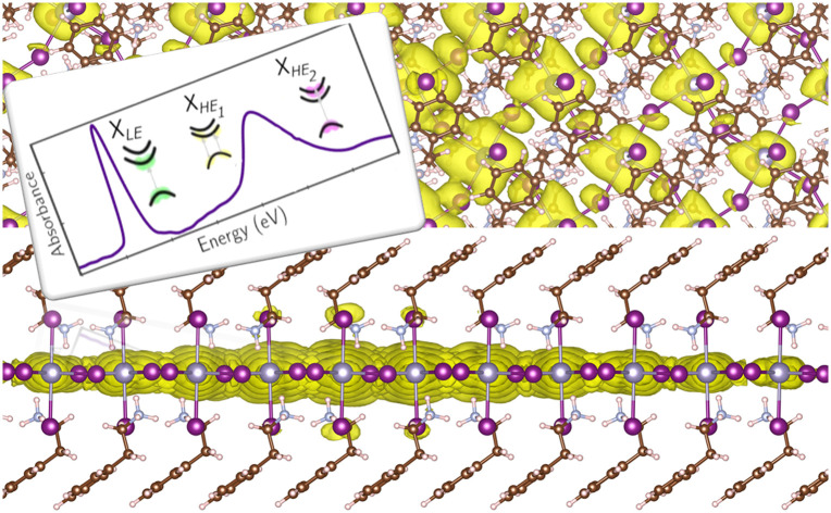
1. Introduction
The re-emergence of two-dimensional Ruddlesden-–Popper metal halides (RPMHs)1–3 with large exciton binding energies has not only fueled technological interest,4,5 but also provided an excellent material platform to explore intriguing excitonic many-body physics6–10via various advanced spectroscopies. From a technological standpoint, such spectroscopic studies are used to determine the material handles that enable optimization of desirable opto-electronic properties – light emission, charge photo-generation and transport.11 To that end, most of the recent works on RPMHs focused on the role played by the organic cation, highlighting how it controls the structural and vibrational parameters and consequently the electronic properties.12,13 Alternatively, mixing of two different organic cations has been suggested as a way to self-assemble RPMHs of varied thicknesses with reduced defect densities and with excellent luminescence efficiencies.14–18
Most of the investigations, however, have been performed on lead-based systems, leaving the effect of the metal cation on the fine-structure excitonic characteristics, in some way, as an open question. This problem garners relevance due to the growing interest in tin-based19–30 and tin-alloyed31,32 metal halide perovskites driven by environmental and stability concerns caused by the use of lead.33 Substitution of lead with Sn2+ 34 or Ge2+ 32,35 also allows us to address some of the contested claims on the peculiar characteristics of excitons in RPMHs that distinguish them from their counterparts in other 2D semiconductors.36 The imposing role of lattice dressing, the resultant polaronic effects, and the unique spin-structure due to the large spin–orbit coupling indeed are under-explored concepts in the context of exciton physics in 2D materials. Pertinently, due to the lighter mass of the tin ion compared to the lead ion, the role of the organic cation can be expected to increase. Thus, tin substitution may also provide an experimental way to expand strategies to control excitonic characteristics. These issues can be addressed by a rigorous comparison of spectroscopic signatures of excitons in RPMHs with comparable structural parameters, but with controlled substitution of the metal cation.
In this work, we perform steady-state and time-resolved spectroscopy of a prototypical RPMH based on tin, phenethylammonium tin iodide ((PEA)2SnI4, PEA = C6H5(CH2)2 NH3+): in addition to the first excitonic resonance well below the carrier continuum, we identify higher energy excitonic states in the spectroscopic structures. Notably, the origin of multiple peaks at the energy of the primary exciton in the linear optical spectra of RPMHs has been discussed at length in the literature, citing either the emergence of multiple excitonic states,37 or vibronic progression.38 However, the nature of such higher energy states is debated. By using state-of-the-art ground and excited-state ab initio simulations, we explain the microscopic origin of the higher energy spectral features observed in the steady state optical absorption spectrum. By means of time-resolved measurements we identify the presence of an additional exciton relaxation channel in the nanosecond regime, which can be explained by the specific higher lying excitonic states, found for (PEA)2SnI4, which act as population reservoir for a part of photo-generated carriers. We also provide a comprehensive analysis of the ultrafast photo-excitation dynamics and of the nature of exciton–phonon interactions in (PEA)2SnI4.
2. Results and discussion
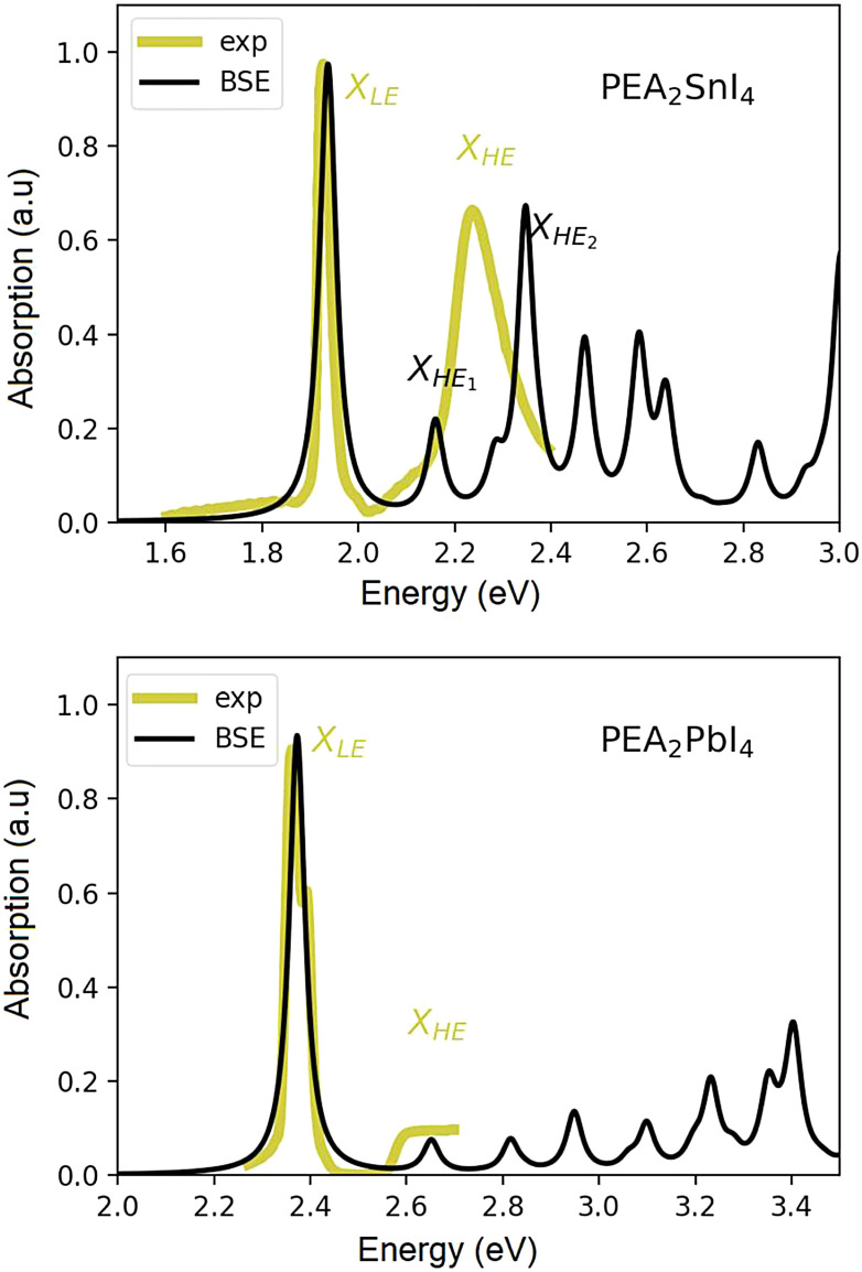
The experimental absorption spectrum of a poly-crystalline thin film of (PEA)2SnI4 taken at 25 K is shown, as a yellow curve, in Fig. 1(a). We observe a red-shift in the entire spectrum with respect to the lead counterpart which is reported for comparison in Fig. 1(b).39 The first peak, labelled as XLE, is associated with the 1s excitonic resonance. A second relatively broad yet clearly discernible peak (labelled as XHE, Fig. 1(a)), centered at around 2.25 eV, suggests the presence of additional excitonic resonances within the continuum, and cannot be accounted for within an empirically modified Elliott framework, as previously used for (PEA)2PbI4 by Neutzner et al.39,40 and Passarelli et al.41 The experimental optical spectrum of (PEA)2PbI4 is reported in panel (b) of the same figure, for a matter of comparison.
Fig. 1. Experimental linear absorption spectrum of the polycrystalline film of (PEA)2SnI4 taken at 25 K (black solid line (a)) and of (PEA)2PbI4 (25 K, black solid line (b), reproduced with permission from ref. 39.). Theoretical spectra obtained via DFT+GW+BSE simulations at 0 K for (PEA)2SnI4 (a) and (PEA)2PbI4 (b).
The calculated GW + BSE optical spectra of both materials are reported as black curves in Fig. 1. In each case, the energy of the first exciton peak has been aligned to the experimental one (see the ESI† for a more extended discussion) for better comparison. Here, we focus on the nature and origin of the second optical resonance in the Sn-based system and compare the photo-physical scenario, from a theoretical perspective, with that of the Pb-based one. All the computational details are reported in the ESI† section of the manuscript, while the structural models considered are discussed in the next section.
2.1. Ground and excited state ab initio calculations
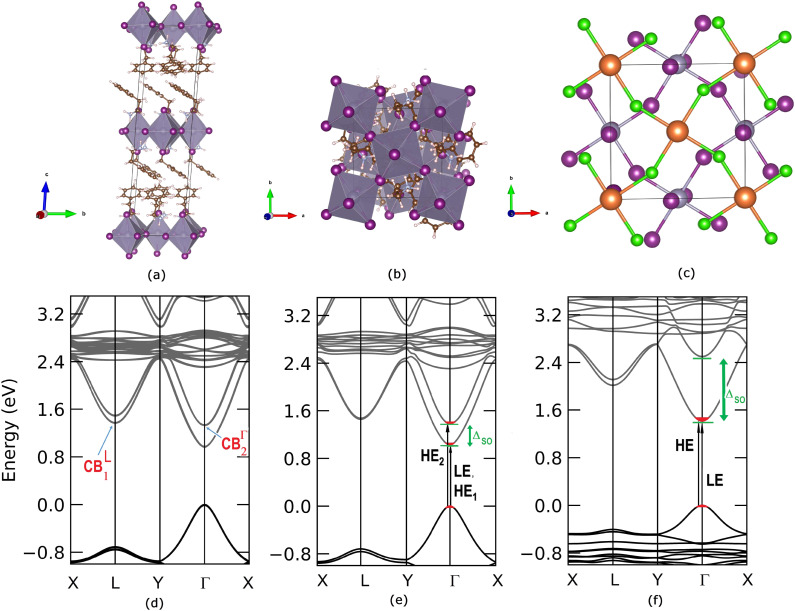
We start the ab initio ground and excited state Density Functional and Many-Body Perturbation Theory (namely GW and BSE methods) study, moving from the experimental X-ray diffraction (XRD) data for (PEA)2SnI4 as given by Zhang et al.42 We fully relax the atomic structure (see Fig. 2(a–c) and the ESI† for structural details) obtaining very good agreement with the experimentally reported one, with variations in the overall volume smaller by about 1.8%. As visible in Fig. 2, (a) for lateral and (b) top view, respectively, two stacked inorganic layers are present in the unit cell. Such layers are characterized by the same structural distortion in terms of amplitude I–Sn–I angle of ∼154° (see panel (c) of the same figure). For this reason, beyond a small splitting due to layer–layer interaction, their associated electronic states are essentially degenerate, as shown in panel (d) of same Fig. 2. A direct Γ → Γ, (indirect, Γ → L) bandgap of 0.96 eV (1.20 eV) is observed at this level of theoretical approximation.42 These results are consistent with recently reported calculated data.43
Fig. 2. (a) Lateral and (b) top view of the PAW/PBE-D3 optimized structure of (PEA)2SnI4. (c) Still top view of the optimized structure of PEA2SnI4 with the highlighted inorganic motif of the two, top (orange, Sn; green, I) and bottom (mauve, Sn; purple, I), layers. (d) PAW/PBE-D3 + SOC calculated bandstructure for the (PEA)2SnI4 bilayer and (e) for the monolayer. For the sake of comparison (f) the PAW/PBE-D3 calculated bandstructure for the (PEA)2PbI4 monolayer is similarly reported. [mauve (and orange in (c)): Sn; purple (and green in (c)): I; brown: C; cyan: N; white: H atoms].
It is worth pointing out that the splitting (Δso) of 0.36 eV in the conduction band minimum (CBm) at Γ raises as a consequence of the spin–orbit interaction. Furthermore, the CBm at L is almost degenerate ( of splitting) with the highest energy splitted (CBΓ2) conduction band at Γ (see Fig. 2(a)). Fig. S1 in the ESI† reports the corresponding bandstructure without including relativistic effects, where the lack of CB splitting is clearly evident, both at Γ and at L. Considering the fact that the two inorganic layers are almost energetically equivalent44 and with the aim to reduce the computational effort of many body perturbation theory (MBPT) calculations (the cell with two inorganic layers counts 188 atoms), we look then also at the single-layer structure discussed by Sheikh et al.45 whose DFT bandstructure is reported in Fig. 2(e). An almost identical dispersion to the two-layers atomic structure, is found with a very similar bandgap of 1.03 eV and a ΔSO which is still 0.36 eV at Γ point. For the sake of comparison with the tin based system and in order to perform the many-body excited-state analysis, we consider the single layer structure of (PEA)2PbI4 obtained from previously reported experimental data46 and whose bandstructure is reported in panel (f) of Fig. 2. Consistently with both experimental and theoretical literature,47,48 the SO splitting is clearly maximized when the B-sites are occupied by Pb atoms, being ΔPbSO = 1.08 eV, and in agreement with previous works, as in the 3D case, the SO splitting is mainly localized on the conduction band edge states.47,49–51
The orbital analysis (see Table S1 in the ESI†) reveals quite close similarities between the stacked, bilayer structure and the monolayer one. In both cases, indeed, the valence band maximum (VBm) is dominated by the combination of equatorial, in-plane, 5px, 5py iodine orbitals, tin 5s, and apical, out-of-plane 5pz I orbitals. The CBm is identically populated by 5px and 5py Sn orbitals combined with marginal amounts of in-plane I atom 5s orbitals. For the sake of completeness, we compare such data with those of the (PEA)2PbI4 monolayer and observe, mutatis mutandis, an almost identical trend with the Sn based counterpart for what concerns the VBm. On the other hand, the CBm is mainly constituted by in-plane Pb 6px and 6py orbitals both at Γ and at the L point. Through the diagonalization of the excitonic Hamiltonian we are able to carry out the analysis of the excitonic BSE optical peaks. For (PEA)2SnI4 we find that while the first optical resonance XLE is due to a strongly bound (1s) exciton involving direct transitions around Γ (highlighted with red in Fig. 2(e)) from highest occupied to lowest unoccupied energy states (LE, panel (e) of Fig. 2), the second experimental optical peak around 2.25 eV (XHE), is associated not only to a 2s excitonic resonance (of the same excitonic series), HE1 in panel (e) of Fig. 2, but also to a different exciton, HE2, which is built up from the same set of highest occupied states at Γ, but from higher-lying CBΓ2 states, split by spin–orbit interaction. The corresponding analysis of the GW + BSE optical spectrum of (PEA)2PbI4, shows that the first peak (XLE is associated with 1s exciton (LE, panel (f) of Fig. 2). The calculated 2s transition of the exciton series (HE panel (f) of Fig. 2) overlaps with the carrrier continuum, characterized by a well defined band edge at about 2.55 eV in the experimental spectrum. Overlap of the higher lying excitonic transitions with the continuum has been previously noted by Passerelli et al.41 Due to a larger SOC conduction band splitting, the excitonic lines calculated in this spectral region do not involve the higher-lying conduction band. Furthermore, from bandstructure (see the next section), we see how  are almost identical in (PEA)2SnI4 but not in (PEA)2PbI4. This suggests that finite-momentum excitons can play different roles in the observed dynamics of Sn- or Pb-based 2D perovskites. It is worth stressing that ab initio real-time electron-dynamics simulations are still in their infancy, but that noticeable examples in the field of perovskites are already reported in the literature:52,53 such analysis would be beneficial also in our present case. Nevertheless, due to the complexity of the considered structural models we remain at the steady-state level of analysis, keeping the dynamical simulations for possible future investigations.
2.2. Photo-excitation dynamics
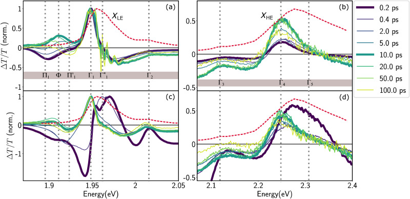
We acquire the differential transmission (DT) spectra – time and spectrally resolved changes in the transmission of a probe pulse induced by a pump pulse – with the pump energy tuned to the energy of XLE at 1.96 eV, thus resonantly generating the low energy excitons, and with the pump energy at 3.1 eV associated to hot carrier excitation. Fig. 3 shows the normalized DT spectra at different pump–probe delays for resonant (a and b) and hot carrier (c and d) excitations. All the spectra in Fig. 3 are acquired at 77 K and on the same sample (spectra that are not normalized are shown in Fig. S4, ESI†). We highlight the dynamics at two different spectral regions around the energies of XLE and XHE.
Fig. 3. Differential transmission spectra of (PEA)2SnI4 upon (a and b) resonant excitation (Epump = 1.96 eV) of the lowest lying excitonic states (c and d) non-resonant excitation of hot free carriers (Epump = 3.1 eV). The DT signal both in the (a and c) XLE and (b and d) XHE regions is normalized to the maximum in XLE. As a reference, the steady-state absorbance spectrum is shown as a red dashed line. All experiments were performed at 77 K with a pump intensity of 350 μW cm−2.
It is clear that the DT dynamics are defined by the presence of multiple time-evolving and overlapping bands. Despite the challenge presented by the complexity of the spectral lineshapes, we are able to identify the most relevant bleach features and relate them to the different states XLE, XHE1 and XHE2: the differential transmission dynamics can then be used as a very sensitive probe for the interaction of the population of different excitonic series. For the sake of convenience, we label the relevant positive photo-bleach (PB) bands with Γ, stimulated emission (SE) bands with Φ and negative photo-induced absorption (PA) bands with Π. The primary spectral feature under both the excitation conditions is a prominent positive ΔT/T signal at 1.95 eV labelled as Γ1, at the edge of XLE. We also observe a positive ΔT/T shoulder on the blue side of Γ1, labelled as  , while in the case of resonant excitation it is partially hidden by a negative feature, we will see that its role becomes more prominent in the case of hot carrier excitation. For now, we consider both Γ1 and
  to be signatures of the photo-bleach of a subset of excitonic transitions at XLE where multiple bright and dark excitonic resonances are predicted by our calculations (Fig. 1). We note that Γ1 may have an additional contribution from stimulated emission. Additional PB bands Γ4 and Γ5 are also seen at XHE, with the latter being a low intensity shoulder to Γ4 and more prominent with Epump = 3.1 eV. Further spectral feature include PA and SE features on the red side of Γ1, as well as additional PB peaks Γ2 and Γ3; their assignment and dynamics are further discussed in the ESI.†
Upon resonant excitation at 1.93 eV, we observe an instantaneous appearance of Γ1 and  bands owing to exciton generation within the excitation pulse duration. A lower lying exciton state is populated in a few picoseconds resulting in a SE feature at Φ. Similar inter-exciton dynamics have been observed via photoluminescence by Folpini et al.19 The details of the dynamics in this spectral range are hard to isolate due to the close spectral overlap between different features; in particular, the temporal evolution of negative features Π1 and
  , both of which can be associated with the exciton PA, is partially obscured by the competing growth in the intensity of positive features such as Φ. Such a spectral congestion can be addressed by using two-dimensional spectroscopy,7 which is out of the scope of the current work.
In the XHE range of the DT spectrum, shown in Fig. 3(b), we observe the instantaneous appearance of a clear PB feature at Γ4, which matches with the lower energy portion of the XHE in the linear absorption spectrum. Based on the theoretical calculations presented earlier, we assign Γ4 to the PB of states similar to XHE1 (see Fig. 2(e)), associated with the 2s state in the same excitonic series as XLE. Thus, here we are resonantly generating XLE excitons and concurrently we observe the PB of the higher lying XHE1, due to depletion of their common ground state. The spectral matching of XHE1 and Γ4 is not exact, with a discrepancy of about 100 meV. However, the heavy influence of phonon scattering effects absent in our theoretical calculations, hinders an exact estimate of the energy of higher lying excitonic Rydberg states, and as such the qualitative correspondence we observe is still satisfactory in the scope of this work.
Despite the complex spectral structure, a simple photophysical scenario may be inferred from Fig. 3; resonant excitation generates exciton (XLE) population with an associated photobleach (and possibly SE) at Γ1 and  , photoinduced absorption at Π1 and photobleach at Γ4, which belong to the same excitonic series. In a few picoseconds, population is transferred from Γ1 to a lower lying emissive exciton state with SE at Φ. Overall the exciton population relaxes to the ground state in hundreds of picoseconds, as also substantiated by the PL dynamics discussed in ref. 19.
Generation of hot carriers with a pump energy much higher than that of the XLE exciton (at 3.1 eV) presents a different dynamic scenario (Fig. 3(c and d)). First, Γ1 and  appear in a couple of picoseconds and not instantaneously. Given the negative peak appearing near Γ1 at early delays (<0.5 ps), these dynamics resemble those of a single bleach combined with the derivative-like signature of the Stark shift. A more detailed examination of the spectral shape, which will be discussed in the following, reveals a mismatch between the energy of Γ1 and that of the Stark shift lineshape and to fully describe the dynamics, two closely spaced features must be invoked. The dynamics at early times are dominated instead by the derivative-like lineshape
 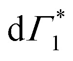 at the energy of
  , indicative of a red-shift in the exciton (XLE) energy. The absence of the derivative feature in the resonant excitation indicates that it is due to the hot charge carriers which screen the Coulomb interactions of the exciton, resulting in a bandgap renormalization (BGR) and a red-shift of the XLE exciton absorption feature. In a few picoseconds, this lineshape evolves into the features observed in the resonant excitation case which include Γ1,
  and Φ. The seemingly delayed appearance of the SE feature Φ in the presence of hot carriers is a result of the dominant contribution of negative features (from the derivative lineshapes), which spectrally overlapped.
We observe correlated picosecond spectral dynamics also in the XHE energy range, especially in the dynamics of the PB feature Γ5 whose energy matches with that of XHE2 states, these higher energy excitonic resonances are composed of the hot carrier states in the electronic bands shown in Fig. 2(e). Accordingly, we assign Γ5 to the population in XHE2 and we observe that it rapidly decays along with the derivative feature at Γ1. This results in an apparent red-shift of the overall PB feature at XHE, that finally settles at Γ4 much alike the resonant case. We interpret the correlated growth dynamics at Γ1 (1.95 eV) and red-shift towards Γ4 (2.25 eV) as signatures of carrier thermalization from the higher to the lower available conduction band that appear over a couple of picoseconds at 77 K.
2.3. Analysis of the DT spectra
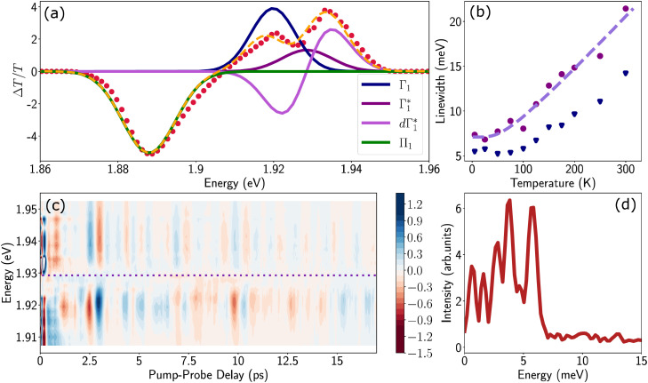
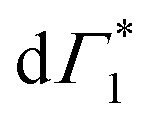
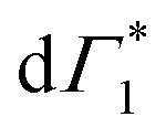
Spectral congestion with overlapping features in the spectra shown Fig. 3(c) prevents a robust analysis of the spectral dynamics at XLE, even for DT spectra taken at 5 K. At higher temperatures, this task is even more challenging due to the temperature induced broadening of the overlapping spectral features (Fig. S5, ESI†). Nevertheless, we construct an empirical yet quantitative model that can capture the most salient characteristics of the observed DT dynamics. We consider that the DT spectrum in the XLE region (1.88–1.96 eV) at 500 fs and at 5 K is composed of four components: (i) a PA band (Π) signature centered around 1.89 eV (ii) a relatively narrow positive ΔT/T band centered at 1.915 eV (Γ1), (iii) a slightly broader peak at 1.935 eV ( ) and (iv) a first derivative of the peak at 1.935 eV (
 ), see Fig. 4(a). We reproduce the DT spectra at all the pump–probe delays with time dependent amplitudes of the four associated components to account for the significant inhomogeneous broadening characteristic of RP metal halides,54–56 we model our spectra using Gaussian rather than Lorentzian linshapes. The fitting procedure, described in more detail in the ESI† yields robust and accurate fits from 5 K up to 300 K; a comparison of experimental data and fits at 5 K is shown in Fig. S6 (ESI†).
Fig. 4. (a) Differential transmission spectrum upon non-resonant pumping (Epump = 3.1 eV), for T = 5 K, τ = 0.5 ps (red dots) and the corresponding fit (dashed line). The model used for fitting contains the PB of Γ1 and  (positive Gaussian features), the energy shift of the excitonic state (derivative Gaussian shape
  ) and an associated excited state PA Π1 (negative Gaussian feature). (b) Widths of the fit components for Γ1 (triangles) and
  (circles). A fit with the dispersion relation of optical phonons (dashed red line) gives an estimate of the LO phonon energy of 14.7 meV. (c) Two dimensional map showing the time resolved coherent oscillations upon hot carrier excitation pumping at 3.1 eV, as a function of pump delay time and detection energy. The observed oscillations persist for longer than 20 ps. The nodal point at E = 1.927 eV marks the position of the exciton coupled to the observed coherent phonons. (d) Fourier transform spectrum of the oscillatory dynamics displayed in (c), and integrated over all the probe energies. This corresponds to the resonant impulsive stimulated Raman spectrum of (PEA)2SnI4 at 5 K.
The peak positions of  , Γ1 and Π1 (Fig. S7(a), ESI†) show a consistent blue shift with increasing temperature and a constant energy separation of 40 meV between them. This corroborates the assignment of Π1 as PA to a biexciton with 40 meV binding energy, in line with previously reported values.7 Their respective linewidths are also comparable (Fig. S7(b), ESI†), although the linewidth of Γ1 is consistently smaller at all temperatures, see Fig. 4(b). The increasing linewidth with temperature is clearly an outcome of increased scattering with phonons. We fit the linewidth
 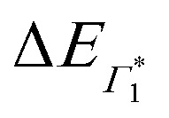 as a function of temperature with the dispersion relation
  , where G represents the temperature independent inhomogeneous broadening and kB is the Boltzmann constant.57 We obtain the exciton–phonon coupling constant γ of 10 meV, with the LO phonon energy ELO estimated to be 15 meV. Strikingly, these numbers are comparable to the phonon energy of 17 meV estimated for (PEA)2PbI4 by Neutzner et al.39 This may suggest that the nature of exciton–phonon interactions have not been substantially affected due to the tin substitution. Given that the vibrational energy is inversely proportional to the mass of the ions involved, moving tin to lead the phonon energy is expected to change. One plausible explanation is that the phonons involved in elastic scattering excitons predominantly involve motion of the halogen atoms and may be the organic moieties. Having said that, we highlight that the estimate of the exciton–phonon coupling obtained through linear spectra can only be considered qualitative and a rigorous analysis of coherent nonlinear lineshapes is essential to extract experimentally accurate parameters as discussed in ref. 55, 56. The actual energies may vastly differ, which will be discussed in a forthcoming publication.
We can obtain more rigorous insights into the phonon dynamics by analyzing the coherent oscillations in the ΔT/T response that are observed atop the population dynamics at 5 K. The ultrashort pump pulse impulsively generates a coherent vibrational wavepacket through resonant impulsive stimulated scattering (RISRS).6 The evolution of the wavepacket along the potential energy surface of the ground state results in an oscillatory DT signal superimposed on the independently evolving dynamics at the energy of XLE. Given the large anharmonicity of the RPMH lattice, these oscillations are typically visible only at low temperatures where the phonon–phonon scattering is minimum, thus explaining their dominant role at 5 K. The coherent oscillations, obtained by subtracting the decay dynamics (modelled as a 5th order polynomial), are shown as a 2D beating map in Fig. 4(c). Their Fourier transform along the pump–probe delay integrated over probe energies (Fig. 4(d)) represents the spectrum of optical phonons generated via the RISRS process. We observe multiple peaks below 7 meV. The main components have a frequency ν = 1–1.5 THz. Phonons in this spectral range, consistent with motions of the Pb–I cage in lead-based RP metal halides,58,59 suggest a dominant contribution from the motion of the Sn–I octahedra. Intriguingly, despite the lighter tin ions, the observed energies are slightly lower than that of their lead counterpart.6
The coherent phonons generated in the RISRS experiment represent the lattice modes that are coupled to the electronic transitions resonant with the pump energy. Thus, the modes shown in Fig. 4(d) upon excitation at 3.1 eV, are those coupled to free carriers. The reason to observe them at the energy of XLE is that their evolution in the ground state also modulates the absorption of the excitonic resonances they are dressing.
We observe a characteristic structure of the modulation amplitude, with a nodal null point at 1.927 eV together with a π-shift in the relative phase of the oscillations at this probe energy. Such a nodal point represents the peak-energy of the resonance which is coupled to and modulated by the coherent phonons.6 It is worth noting that this energy does not correspond to the peak energy of XLE in linear absorption, which suggests that XLE is composed of multiple broad resonances, only one of which is being dressed by these phonons. Coincidentally, the nodal point energy matches exactly with the peak-position of  considered in the DT spectral analysis (see Fig. 4(b)). Notably, the resonance at Γ1 is not coupled to the generated coherent phonons.
Two explanations may be invoked to rationalize this observation. One follows the work of Thouin et al.,6 where Γ1 and  represent two exciton–polaron states that are distinctly dressed by the lattice phonons. Alternatively, we can consider that Γ1 is a SE band, given that it coincides with one of the peaks in the PL spectrum (see Fig. S3 and S6(a), ESI†). RISRS signals arise due to the evolution of the vibrational wavepacket in the electronic ground-state and consequently do not modulate the emission rate of the excited-state, thus, one expects to observe RISRS exclusively at the PB signatures that probe the absorption probabilities and not in the SE features. The relatively narrow linewidth of Γ1 further corroborates this assignment; furthermore, recent results indicate that this material indeed shows strong stimulated emission compatible with lasing at the cryogenic temperature, corroborating this picture.60
We will now elaborate on the dynamics of the fit parameters, shown in Fig. S7 and S8 (ESI†), hypothesizing that Γ1 is indeed a SE signature. Any discrepancy in this assignment however will not drastically affect the derived photo-physical model, since SE as well as a PB may be used as spectral signatures for the evolving exciton population. Firstly, after a few picoseconds, the DT spectrum is composed of Γ1,  and Π1, all of which show correlated decays over hundreds of picoseconds, consistent with the PL dynamics of the relaxation of the photo-excited charge carriers.19 Atop the decay, we also observe a growth in the intensity of
  within 250 ps, particularly evident at temperatures below 50 K. We had previously discussed these dynamics in the context of population exchange between dark and bright excitonic states in ref. 19.
At early times (<10 ps), we observe the derivative component at  (
(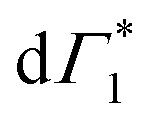 in Fig. 4(a)) disappearing in about 3 ps at 5 K and less than 500 fs at RT. This spectral feature indicates a photo-induced red-shift in the exciton (
 ) energy, which is a consequence of screening of Coulomb interactions by hot charge carriers and subsequent BGR. Notably, the screening of exciton absorption is perceived at energy
  , which further substantiates our assignment of
  to PB and Γ1 to SE. The screening and accordingly
 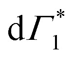 is quenched as the hot carriers thermalize to form bound excitons over a few picoseconds. This timescale exactly matches with the formation dynamics of Γ1, which is a fingerprint of phase-space filling of the excitonic state. Accordingly this timescale represents ultrafast exciton formation that follows hot carrier thermalization. Similar timescales for exciton formation have been reported with more ambiguous THz probes by Folpini el al in (NBT)2PbI4.61
2.4. Carrier thermalization and exciton formation dynamics
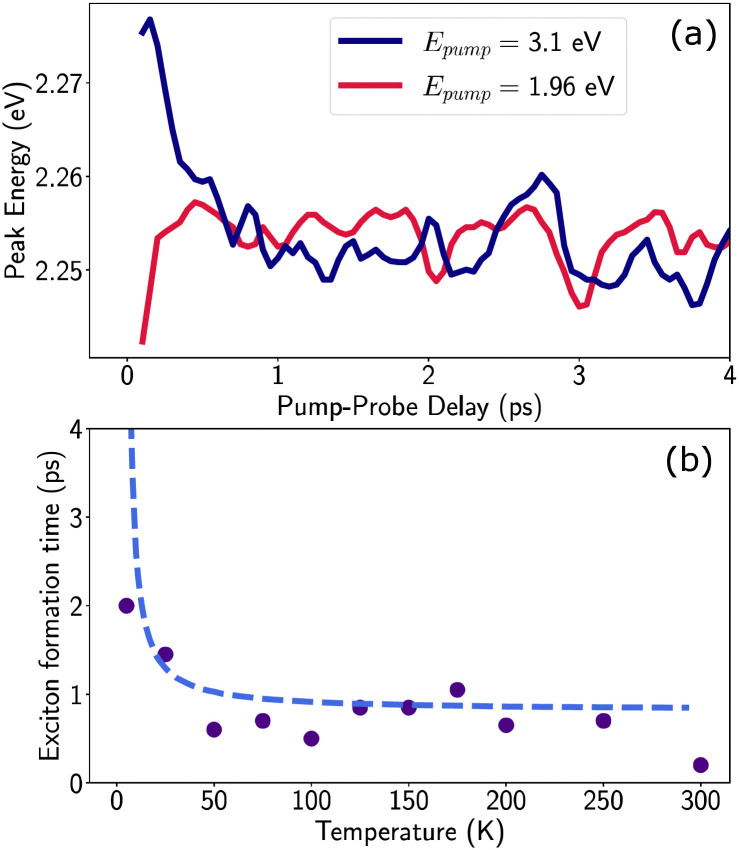
As noted earlier, the DT dynamics at XHE also are indicative of ultrafast hot carrier thermalization and exciton formation, the spectral signature of which lies in the apparent red-shift in the peak energy of the PB feature at XHE. The dynamics of the corresponding peak-shift at 77 K are shown in Fig. 5(a) for the resonant and hot carrier excitation case (red and blue line respectively): while no red shift is observed in the resonant case, the hot carrier dynamics match those observed in XLE, specifically in the loss of the derivative feature 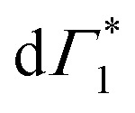 and the appearance of Γ1.
Fig. 5. (a) Peak position of the XHE feature at T = 77 K as a function of pump–probe delay, while for excitation resonant to the excitonic transition (red) no spectral shift occurs, for excitation in the continuum (blue) a red shift occurs in the first picosecond after excitation (b) exciton relaxation time as a function of temperature: as a figure of merit, we consider the time it takes for the XHE peak to match its equilibrium values at long delays when excited in the continuum, up to a 95% tolerance. The resulting exciton formation time is consistent with thermalization driven by 4 meV phonons, as described by the Boltzmann distribution (dashed line).
Given the correlated appearance of  , the red shift of XHE can be used as a figure of merit to compare exciton formation time across different temperatures. The effective relaxation time τrel, defined as the delay when the peak position of XHE(τ) is within 90% of its equilibrium value at long delays (1 ns), is shown in Fig. 5(b) and Fig. S9 (ESI†). This estimate gives an ultrafast exciton formation of less than 2 ps even at 5 K, and points to a scenario in which a large fraction of the excited carriers rapidly relax to the bottom of the band structure due to effective electron–phonon coupling and form a stable exciton population. The temperature dependence of the formation time is consistent with exciton thermalization driven by the scattering of the carriers with LO phonons,62,63 considering the phonon energy to be approximately 4 meV (32 cm−1), the lower energy phonon mode estimated by the RISRS analysis (see Fig. 4(d)).
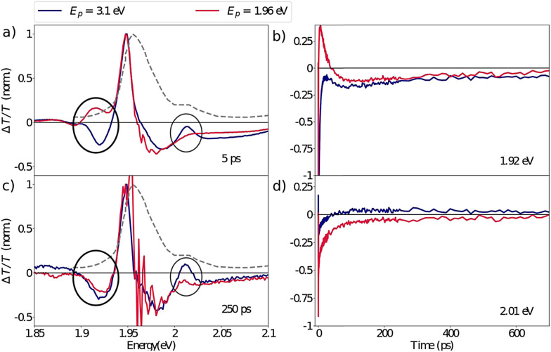
Despite the ultrafast thermalization dynamics and clear spectroscopic evidence of exciton formation, we highlight that even after hundreds of picoseconds the DT spectra obtained with the pump at 3.1 eV do not resemble the resonant excitation spectra. This is particularly striking in the XLE spectral range as highlighted in Fig. 6 where we compare the normalized DT spectra under the two pump conditions at 5 ps and 250 ps. Two pertinent differences can be identified: (a) at early delays, the absence of the SE feature, Φ (1.92 eV) that we had attributed to the population of the lower lying excitonic state with the hot carrier excitations and (b) later, at 250 ps delay, the absence of the Γ2 (2.01 eV) bleach feature with the resonant excitation. We also note that in the XHE region the Γ5 feature has not completely disappeared even after hundreds of picoseconds (see Fig. 3(d)). We interpret the sustained bleach signatures at Γ2 and Γ5 as the state-filling of higher lying excitonic states that trap a part of the photo-generated hot carrier population, resulting in slow exciton formation dynamics. The Γ5 feature can be attributed to the XHE2 excitonic state predicted by the BSE calculations while Γ2 (and Γ3) is not theoretically predicted. Based on this observation, we can conclude that the higher lying states are acting as a population reservoir for the photo-generated carriers. While the origin of the slow inter-exciton dynamics is not fully understood here, their presence is evident.
Fig. 6. Differential transmission spectrum at 77 K of the XLE range at (a) 5 ps (c) 250 ps delay, showing long lived thermalization dynamics: differences between resonant (red line) and non-resonant (blue line) excitation are still found after hundreds of picoseconds. (b and d) Dynamics at the spectral position of (b) Π1 and d) Γ2 respectively on the red and blue side of the resonant pump, showing contributions of opposite sign for tens (Π1) and hundreds of ps (Γ2).
Our analysis indicates that the XHE exciton acts as a population trap for the photo-generated hot carriers resulting in the observed dynamics. Importantly, such slow dynamics are absent in the case of (PEA)2PbI4, as discussed extensively in ref. 64 and several other works. In the case of the lead based system, we observed that carrier thermalization is complete within the first hundreds of femtoseconds, followed by the formation of emissive exciton in less than 10 ps. There are indeed multiple excitons even in (PEA)2PbI4, but energetically closer, and the population transfer from one to the other is shown to be driven by their non-adiabatic coupling through lattice phonons. If similar mechanisms can be invoked in the transfer of population from XHE to XLE in the current case, then the rate of inter-exciton conversion is further reduced as observed here, resulting in the slow transfer dynamics. The details of the mechanism behind the transfer dynamics and the role of the lattice is to be further explored both on theoretical and experimental fronts.
We highlight that the excitonic finestructure has been a topic of debate in (PEA)PbI4, which was attributed to vibronic lineshapes as well as polaronic effects as recently elaborated by Straus and Kagan.65 In an earlier version of this manuscript,66 we predicted that similar lattice contributions may be the cause of the appearance of XHE in the tin system. While multiple excitonic resonances may still originate from lattice based causes, our earlier model was unable to capture an accurate photophysical picture due to the smaller unit cell considered for the calculations. Importantly, we note that in the case of (PEA)2PbI4, multiple resonances observed at the energy of the lowest exciton may be a result of lattice dressing and polaronic effects. Having said that, the topic of investigation in this manuscript is not the origin of the excitonic finestructure, but of the higher lying excitonic resonances. We attribute this to the presence of a second conduction band, created by the spin–oribit coupling effects.
3. Conclusions
We investigated the effect of the metal cation substitution on the optical properties of a 2D Ruddlesden–Popper metal halide. Upon substitution of lead with tin, the static absorbance of (PEA)2SnI4 reveals the appearance of higher energy excitonic resonances never observed in the corresponding lead halides. Based on ab initio calculations, we identify multiple excitonic resonances in the probed spectral range which are composed of excitations at various regions of the carrier phase-space. Even though they originate from different conduction states (due to spin–orbit splitting), they share the same hole states in the valence band. The PB signatures of XHE1 on the other hand stems from an excited state in the XLE series, which is detected in differential transmission spectroscopy even when XLE states are uniquely excited. We also investigated the ultrafast hot carrier thermalization dynamics and exciton formation dynamics and their temperature dependence to evaluate the role of exciton–phonon interactions. Notably, although we observe a change in the energy of the phonons due to tin substitution, the nature of exciton–phonon interactions appears to be unaffected by the choice of the metal cation.
In addition to the picosecond phonon-assisted thermalization, the presence of XHE and other higher energy excitonic states results in a slower relaxation channel for the photo-excited population towards the lowest energy emissive exciton at XLE. Such an excitonic landscape offers a possibility to create high energy reservoirs of exciton population that preserve the photo-excited population from many-body interactions and other loss channels prevalent in high density applications, particularly in lasers.
4. Materials and methods
4.1. Synthesis
The perovskite precursors (PEA)I (Dyesol) and SnI2 (TCI) were mixed in a 1 : 1 stoichiometric ratio to form 0.2 M solutions in DMF (dimethylformamide, anhydrous, Sigma Aldrich). The powders were left to dissolve overnight, and then the solution was heated up do 100° 1 hour before the deposition process. (PEA)2SnI4 polycrystalline thin films were spin coated from the hot solution at 5000 rpm on fused silica substrates (previously treated under oxygen plasma). The film was then annealed at 100° for 15 minutes on a hotplate. The entire process was performed under an inert atmosphere in a N2 filled glove-box. To avoid tin oxidation, the sample was transported in a vacuum sealed container up to its placement in a gas cryostat (Oxford Instruments Optistat CF) vacuum chamber, where it was subsequently kept under an inert helium atmosphere.
4.2. Ab initio calculations
In the DFT ground-state simulations, the electron exchange–correlation functional proposed by Perdew–Burke–Ernzerhof (PBE)67 as implemented in the VASP code68–71 along with the D3 dispersion corrections has been applied.72,73 The projector augmented wave (PAW) method74,75 has been similarly adopted using a cutoff energy of 600 eV for the plane-wave basis set. The Brillouin Zone (BZ) was sampled by means of a Γ-centred 6 × 6 × 2 mesh. Optimization of ionic positions and lattice parameters was performed until forces were lower than 0.02 eV Å−1. We then used the most energetically stable structure to determine the role of many-body effects by using the many-body code Yambo (see the ESI† for further information on the computational procedure and details).76,77
4.3. Differential transmission set-up
Ultrafast pump probe experiments were performed using a Ti–Sapphire chirped pulse amplified source, with 1 mJ output energy, 1 kHz repetition rate, 800 nm central wavelength and 100 fs pulse duration. Excitation pulses at 490 nm were generated by non-collinear optical parametric amplification (NOPA) in β-barium borate (BBO) crystals. Pump pulses(pulse energy 0.25 nJ) were focused in a 300 μm diameter spot resulting in a pump fluence of 354 μW cm−2. Probing was achieved in the visible – near infrared region (530–1000 nm) by using white light (WL) generated in a thin YAG plate. The plate was pumped by means of a broadband collinear optical parametric amplification (OPA) with a spectrum centred at around 1200 nm. Transient transmission spectra were recorded using an optical multichannel analyser (OMA). The measured quantity is the normalized transmission change, ΔT/T. To ensure that the acquired transient signals are not affected by sample degradation, the white light static transmission through the sample was constantly monitored: any oxidation or photodegradtion of the material would manifest as a change in the transmitted WL spectrum. No such changes were observed during the entire data collection (see Fig. S10, ESI† for representative WL spectra for a 30 minutes measurement at room temperature).
Author contributions
The experimental measurements were performed by GF and LM under the supervision of GC and ARSK. Data analysis was performed by GF and ARSK. The sample was fabricated by DC under the supervision of AP. The theoretical calculations and analysis were performed by MP and GG. The manuscript was prepared by GF, MP, GG and ARSK with inputs from all the authors. The project was conceived by ARSK.
Conflicts of interest
There are no conflicts to declare.
Supplementary Material
Acknowledgments
MP and GG acknowledge the access to high-performance computing resources at Cineca under Iscra-B and iscra-C initiatives. MP acknowledges CN1 (Spoke6) – Centro Nazionale di Ricerca in the High-Performance Computing Big Data and Quantum Computing project and TIME2QUEST INFN project. GG thanks the European Union – NextGenerationEU under the Italian Ministry of University and Research (MUR) National Innovation Ecosystem grant ECS00000041 – VITALITY for funding and acknowledges Università degli Studi di Perugia and MUR for support within the project Vitality. GF and AP ackowledge the funding from the European Unions Horizon 2020 research and innovation program through the ERC project SOPHY under grant agreement no. 771528. D. C. acknowledges funding from the MSCA project under grant agreement no. 839480 (PERICLeS).
Electronic supplementary information (ESI) available. See DOI: https://doi.org/10.1039/d2ma00136e
Notes and references
- Kagan C. R. Mitzi D. B. Dimitrakopoulos C. D. Science. 1999;286:945–947. doi: 10.1126/science.286.5441.945. [DOI] [PubMed] [Google Scholar]
- Shimizu M. Fujisawa J. I. Ishi-Hayase J. Phys. Rev. B: Condens. Matter Mater. Phys. 2005;71:205306. doi: 10.1103/PhysRevB.71.205306. [DOI] [Google Scholar]
- Kahmann S. Duim H. Fang H.-H. Dyksik M. Adjokatse S. Rivera Medina M. Pitaro M. Plochocka P. Loi M. A. Adv. Funct. Mater. 2021;31:2103778. doi: 10.1002/adfm.202103778. [DOI] [Google Scholar]
- Chen Y. Sun Y. Peng J. Tang J. Zheng K. Liang Z. Adv. Mater. 2018;30:1703487. doi: 10.1002/adma.201703487. [DOI] [PubMed] [Google Scholar]
- Liu X. K. Xu W. Bai S. Jin Y. Wang J. Friend R. H. Gao F. Nat. Mater. 2021;20:10–21. doi: 10.1038/s41563-020-0784-7. [DOI] [PubMed] [Google Scholar]
- Thouin F. Valverde-Chávez D. A. Quarti C. Cortecchia D. Bargigia I. Beljonne D. Petrozza A. Silva C. Srimath Kandada A. R. Nat. Mater. 2019;18:349–356. doi: 10.1038/s41563-018-0262-7. [DOI] [PubMed] [Google Scholar]
- Thouin F. Neutzner S. Cortecchia D. Dragomir V. A. Soci C. Salim T. Lam Y. M. Leonelli R. Petrozza A. Srimath Kandada A. R. et al. . Phys. Rev. Mater. 2018;2:034001. doi: 10.1103/PhysRevMaterials.2.034001. [DOI] [Google Scholar]
- Tao W. Zhou Q. Zhu H. Sci. Adv. 2020;6:eabb7132. doi: 10.1126/sciadv.abb7132. [DOI] [PMC free article] [PubMed] [Google Scholar]
- Ishihara T. Hong X. Ding J. Nurmikko A. V. Surf. Sci. 1992;267:323–326. doi: 10.1016/0039-6028(92)91147-4. [DOI] [Google Scholar]
- Goto T. Makino H. Yao T. Chia C. H. Makino T. Segawa Y. Mousdis G. A. Papavassiliou G. C. Phys. Rev. B: Condens. Matter Mater. Phys. 2006;73:115206. doi: 10.1103/PhysRevB.73.115206. [DOI] [Google Scholar]
- Blancon J. C. Even J. Stoumpos C. C. Kanatzidis M. G. Mohite A. D. Nat. Nanotechnol. 2020;15:969–985. doi: 10.1038/s41565-020-00811-1. [DOI] [PubMed] [Google Scholar]
- Cortecchia D. Neutzner S. Kandada A. R. S. Mosconi E. Meggiolaro D. De Angelis F. Soci C. Petrozza A. J. Am. Chem. Soc. 2017;139:39–42. doi: 10.1021/jacs.6b10390. [DOI] [PubMed] [Google Scholar]
- Gong X. Voznyy O. Jain A. Liu W. Sabatini R. Piontkowski Z. Walters G. Bappi G. Nokhrin S. Bushuyev O. et al. . Nat. Mater. 2018;17:550–556. doi: 10.1038/s41563-018-0081-x. [DOI] [PubMed] [Google Scholar]
- Yuan M. Quan L. N. Comin R. Walters G. Sabatini R. Voznyy O. Hoogland S. Zhao Y. Beauregard E. M. Kanjanaboos P. et al. . Nat. Nanotechnol. 2016;11:872–877. doi: 10.1038/nnano.2016.110. [DOI] [PubMed] [Google Scholar]
- Yusoff A. R.-b M. Nazeeruddin M. K. Adv. Energy Mater. 2018;8:1702073. doi: 10.1002/aenm.201702073. [DOI] [Google Scholar]
- Yantara N. Bruno A. Iqbal A. Jamaludin N. F. Soci C. Mhaisalkar S. Mathews N. Adv. Mater. 2018;30:1800818. doi: 10.1002/adma.201800818. [DOI] [PubMed] [Google Scholar]
- Qin C. Sandanayaka A. S. Zhao C. Matsushima T. Zhang D. Fujihara T. Adachi C. Nature. 2020;585:53–57. doi: 10.1038/s41586-020-2621-1. [DOI] [PubMed] [Google Scholar]
- Ishihara T. Takahashi J. Goto T. Phys. Rev. B: Condens. Matter Mater. Phys. 1990;42:11099. doi: 10.1103/PhysRevB.42.11099. [DOI] [PubMed] [Google Scholar]
- Folpini G. Cortecchia D. Petrozza A. Srimath Kandada A. R. J. Mater. Chem. C. 2020;8:10889–10896. doi: 10.1039/D0TC01218A. [DOI] [Google Scholar]
- Liang H. Yuan F. Johnston A. Gao C. Choubisa H. Gao Y. Wang Y. K. Sagar L. K. Sun B. Li P. Bappi G. Chen B. Li J. Wang Y. Dong Y. Ma D. Gao Y. Liu Y. Yuan M. Saidaminov M. I. Hoogland S. Lu Z. H. Sargent E. H. Adv. Sci. 2020;7:1903213. doi: 10.1002/advs.201903213. [DOI] [PMC free article] [PubMed] [Google Scholar]
- Lanzetta L. Marin-Beloqui J. M. Sanchez-Molina I. Ding D. Haque S. A. ACS Energy Lett. 2017;2:1662–1668. doi: 10.1021/acsenergylett.7b00414. [DOI] [Google Scholar]
- Xu H. Jiang Y. He T. Li S. Wang H. Chen Y. Yuan M. Chen J. Adv. Funct. Mater. 2019;29:1807696. doi: 10.1002/adfm.201807696. [DOI] [Google Scholar]
- Cao D. H. Stoumpos C. C. Yokoyama T. Logsdon J. L. Song T. B. Farha O. K. Wasielewski M. R. Hupp J. T. Kanatzidis M. G. ACS Energy Lett. 2017;2:982–990. doi: 10.1021/acsenergylett.7b00202. [DOI] [Google Scholar]
- Zhang X. Wang C. Zhang Y. Zhang X. Wang S. Lu M. Cui H. Kershaw S. V. Yu W. W. Rogach A. L. ACS Energy Lett. 2019;4:242–248. doi: 10.1021/acsenergylett.8b02239. [DOI] [Google Scholar]
- Hou L. Zhu Y. Zhu J. Li C. J. Phys. Chem. C. 2019;123:31279–31285. doi: 10.1021/acs.jpcc.9b10457. [DOI] [Google Scholar]
- Lin J. T. Liao C. C. Hsu C. S. Chen D. G. Chen H. M. Tsai M. K. Chou P. T. Chiu C. W. J. Am. Chem. Soc. 2019;141:10324–10330. doi: 10.1021/jacs.9b03148. [DOI] [PubMed] [Google Scholar]
- Shi E. Yuan B. Shiring S. B. Gao Y. Guo Y. Su C. Lai M. Yang P. Kong J. Savoie B. M. et al. . Nature. 2020;580:614–620. doi: 10.1038/s41586-020-2219-7. [DOI] [PubMed] [Google Scholar]
- Wang Z. Wang F. Zhao B. Qu S. Hayat T. Alsaedi A. Sui L. Yuan K. Zhang J. Wei Z. Tan Z. J. Phys. Chem. Lett. 2020;11:1120–1127. doi: 10.1021/acs.jpclett.9b03565. [DOI] [PubMed] [Google Scholar]
- Nawale V. V. Sheikh T. Nag A. J. Phys. Chem. C. 2020;124:21129–21136. doi: 10.1021/acs.jpcc.0c05301. [DOI] [Google Scholar]
- Dyksik M. Duim H. Zhu X. Yang Z. Gen M. Kohama Y. Adjokatse S. Maude D. K. Loi M. A. Egger D. A. et al. . ACS Energy Lett. 2020;5:3609–3616. doi: 10.1021/acsenergylett.0c01758. [DOI] [Google Scholar]
- Zhang J. Zhu X. Wang M. Hu B. Nat. Commun. 2020;11:2618. doi: 10.1038/s41467-020-16415-1. [DOI] [PMC free article] [PubMed] [Google Scholar]
- Cheng P. Wu T. Liu J. Deng W. Q. Han K. J. Phys. Chem. Lett. 2018;9:2518–2522. doi: 10.1021/acs.jpclett.8b00871. [DOI] [PubMed] [Google Scholar]
- Pecunia V. Occhipinti L. G. Chakraborty A. Pan Y. Peng Y. APL Mater. 2020;8:100901. doi: 10.1063/5.0022271. [DOI] [Google Scholar]
- Mitzi D. B. Feild C. Harrison W. Guloy A. Nature. 1994;369:467–469. doi: 10.1038/369467a0. [DOI] [Google Scholar]
- Mitzi D. B. Chem. Mater. 1996;8:791–800. doi: 10.1021/cm9505097. [DOI] [Google Scholar]
- Straus D. B. Kagan C. R. J. Phys. Chem. Lett. 2018;9:1434–1447. doi: 10.1021/acs.jpclett.8b00201. [DOI] [PubMed] [Google Scholar]
- Srimath Kandada A. R. Silva C. J. Phys. Chem. Lett. 2020;11:3173–3184. doi: 10.1021/acs.jpclett.9b02342. [DOI] [PubMed] [Google Scholar]
- Kahmann S. Duim H. Fang H.-H. Dyksik M. Adjokatse S. Rivera Medina M. Pitaro M. Plochocka P. Loi M. A. Adv. Funct. Mater. 2021;31:2103778. doi: 10.1002/adfm.202103778. [DOI] [Google Scholar]
- Neutzner S. Thouin F. Cortecchia D. Petrozza A. Silva C. Srimath Kandada A. R. Phys. Rev. Mater. 2018;2:064605. doi: 10.1103/PhysRevMaterials.2.064605. [DOI] [Google Scholar]
- Neutzner S. Thouin F. Cortecchia D. Petrozza A. Silva C. Srimath Kandada A. R. Phys. Rev. Mater. 2020;4:059901. doi: 10.1103/PhysRevMaterials.4.059901. [DOI] [Google Scholar]
- Passarelli J. V. Mauck C. M. Winslow S. W. Perkinson C. F. Bard J. C. Sai H. Williams K. W. Narayanan A. Fairfield D. J. Hendricks M. P. et al. . Nat. Chem. 2020;12:672–682. doi: 10.1038/s41557-020-0488-2. [DOI] [PubMed] [Google Scholar]
- Zhang T. Zhou C. Feng X. Dong N. Chen H. Chen X. Zhang L. Lin J. Wang J. Nat. Commun. 2022;13:1–11. doi: 10.1038/s41467-021-27663-0. [DOI] [PMC free article] [PubMed] [Google Scholar]
- Mandal S. Khan B. A. Sarkar P. Comput. Mater. Sci. 2022;211:111545. doi: 10.1016/j.commatsci.2022.111545. [DOI] [Google Scholar]
- Jana M. K. Liu C. Lidin S. Dirkes D. J. You W. Blum V. Mitzi D. B. Chem. Mater. 2019;31:8523–8532. doi: 10.1021/acs.chemmater.9b03208. [DOI] [Google Scholar]
- Sheikh T. Nawale V. Pathoor N. Phadnis C. Chowdhury A. Nag A. Angew. Chem. 2020;132:11750–11756. doi: 10.1002/ange.202003509. [DOI] [PubMed] [Google Scholar]
- Du K.-z. Tu Q. Zhang X. Han Q. Liu J. Zauscher S. Mitzi D. B. Inorg. Chem. 2017;56:9291–9302. doi: 10.1021/acs.inorgchem.7b01094. [DOI] [PubMed] [Google Scholar]
- Even J. Pedesseau L. Dupertuis M.-A. Jancu J.-M. Katan C. Phys. Rev. B: Condens. Matter Mater. Phys. 2012;86:205301. doi: 10.1103/PhysRevB.86.205301. [DOI] [Google Scholar]
- Ishihara T. Takahashi J. Goto T. Solid State Commun. 1989;69:933–936. doi: 10.1016/0038-1098(89)90935-6. [DOI] [Google Scholar]
- Even J. Pedesseau L. Jancu J.-M. Katan C. J. Phys. Chem. Lett. 2013;4:2999–3005. doi: 10.1021/jz401532q. [DOI] [Google Scholar]
- Giorgi G. Fujisawa J.-I. Segawa H. Yamashita K. J. Phys. Chem. C. 2014;118:12176–12183. doi: 10.1021/jp504479c. [DOI] [Google Scholar]
- Giorgi G. Fujisawa J.-I. Segawa H. Yamashita K. J. Phys. Chem. Lett. 2013;4:4213–4216. doi: 10.1021/jz4023865. [DOI] [PubMed] [Google Scholar]
- Lian C. Ali Z. A. Kwon H. Wong B. M. J. Phys. Chem. Lett. 2019;10:3402–3407. doi: 10.1021/acs.jpclett.9b01046. [DOI] [PubMed] [Google Scholar]
- Wei L. She Y. Prezhdo O. V. Halide Perovskites for Photonics. 2021;6:1–54. [Google Scholar]
- Liu A. Nagamine G. Bonato L. G. Almeida D. B. Zagonel L. F. Nogueira A. F. Padilha L. A. Cundiff S. T. ACS Nano. 2021;15:6499–6506. doi: 10.1021/acsnano.0c09244. [DOI] [PubMed] [Google Scholar]
- Thouin F. Cortecchia D. Petrozza A. Kandada A. R. S. Silva C. Phys. Rev. Res. 2019;1:032032. doi: 10.1103/PhysRevResearch.1.032032. [DOI] [Google Scholar]
- Kandada A. R. S., Li H., Bittner E. R. and Silva-Acuña C., Homogeneous optical linewidths in hybrid Ruddlesden–Popper metal halides can be only measured using nonlinear spectroscopy, 2021 [Google Scholar]
- Lee J. Koteles E. S. Vassell M. Phys. Rev. B: Condens. Matter Mater. Phys. 1986;33:5512. doi: 10.1103/PhysRevB.33.5512. [DOI] [PubMed] [Google Scholar]
- Leguy A. M. Goñi A. R. Frost J. M. Skelton J. Brivio F. Rodrguez-Martnez X. Weber O. J. Pallipurath A. Alonso M. I. Campoy-Quiles M. et al. . Phys. Chem. Chem. Phys. 2016;18:27051–27066. doi: 10.1039/C6CP03474H. [DOI] [PubMed] [Google Scholar]
- Grechko M. Bretschneider S. A. Vietze L. Kim H. Bonn M. Angew. Chem., Int. Ed. 2018;57:13657–13661. doi: 10.1002/anie.201806676. [DOI] [PubMed] [Google Scholar]
- Alvarado-Leaños A. L. Cortecchia D. Saggau C. N. Martani S. Folpini G. Feltri E. Albaqami M. D. Ma L. Petrozza A. ACS Nano. 2022;16:20671–20679. doi: 10.1021/acsnano.2c07705. [DOI] [PMC free article] [PubMed] [Google Scholar]
- Folpini G. Gatto L. Cortecchia D. Devetta M. Crippa G. Vozzi C. Stagira S. Petrozza A. Cinquanta E. J. Chem. Phys. 2020;152:214705. doi: 10.1063/5.0008608. [DOI] [PubMed] [Google Scholar]
- Low F. E. Pines D. Phys. Rev. 1955;98:414. doi: 10.1103/PhysRev.98.414. [DOI] [Google Scholar]
- Hendry E. Koeberg M. Bonn M. Phys. Rev. B: Condens. Matter Mater. Phys. 2007;76:045214. doi: 10.1103/PhysRevB.76.045214. [DOI] [Google Scholar]
- Thouin F. Srimath Kandada A. R. Valverde-Chávez D. A. Cortecchia D. Bargigia I. Petrozza A. Yang X. Bittner E. R. Silva C. Chem. Mater. 2019;31:7085–7091. doi: 10.1021/acs.chemmater.9b02267. [DOI] [Google Scholar]
- Straus D. B. Kagan C. R. Annu. Rev. Phys. Chem. 2022;73:403–428. doi: 10.1146/annurev-physchem-082820-015402. [DOI] [PubMed] [Google Scholar]
- Folpini G., Palummo M., Cortecchia D., Moretti L., Cerullo G., Petrozza A., Giorgi G. and Srimath Kandada A. R., ChemRxiv, 2021, preprint 10.26434/chemrxiv-2021-qcm36-v2 [DOI] [PMC free article] [PubMed]
- Perdew J. P. Burke K. Ernzerhof M. Phys. Rev. Lett. 1996;77:3865–3868. doi: 10.1103/PhysRevLett.77.3865. [DOI] [PubMed] [Google Scholar]
- Kresse G. Hafner J. Phys. Rev. B: Condens. Matter Mater. Phys. 1993;48:13115–13118. doi: 10.1103/PhysRevB.48.13115. [DOI] [PubMed] [Google Scholar]
- Kresse G. Hafner J. Phys. Rev. B: Condens. Matter Mater. Phys. 1994;49:14251–14269. doi: 10.1103/PhysRevB.49.14251. [DOI] [PubMed] [Google Scholar]
- Kresse G. Furthmüller J. Comput. Mater. Sci. 1996;6:15–50. doi: 10.1016/0927-0256(96)00008-0. [DOI] [Google Scholar]
- Kresse G. Furthmüller J. Phys. Rev. B: Condens. Matter Mater. Phys. 1996;54:11169–11186. doi: 10.1103/PhysRevB.54.11169. [DOI] [PubMed] [Google Scholar]
- Grimme S. Antony J. Ehrlich S. Krieg H. J. Chem. Phys. 2010;132:154104. doi: 10.1063/1.3382344. [DOI] [PubMed] [Google Scholar]
- Grimme S. Ehrlich S. Goerigk L. J. Comput. Chem. 2011;32:1456–1465. doi: 10.1002/jcc.21759. [DOI] [PubMed] [Google Scholar]
- Blöchl P. Phys. Rev. B: Condens. Matter Mater. Phys. 1994;50:17953–17979. doi: 10.1103/PhysRevB.50.17953. [DOI] [PubMed] [Google Scholar]
- Kresse G. Joubert D. Phys. Rev. B: Condens. Matter Mater. Phys. 1999;59:1758–1775. doi: 10.1103/PhysRevB.59.1758. [DOI] [Google Scholar]
- Marini A. Hogan C. Grüning M. Varsano D. Comput. Phys. Commun. 2009;180:1392–1403. doi: 10.1016/j.cpc.2009.02.003. [DOI] [Google Scholar]
- Sangalli D. Ferretti A. Miranda H. Attaccalite C. Marri I. Cannuccia E. Melo P. Marsili M. Paleari F. Marrazzo A. Prandini G. Bonfà P. Atambo M. O. Affinito F. Palummo M. Molina-Sánchez A. Hogan C. Grüning M. Varsano D. Marini A. J. Phys.: Condens. Matter. 2019;31:325902. doi: 10.1088/1361-648X/ab15d0. [DOI] [PubMed] [Google Scholar]
Associated Data
This section collects any data citations, data availability statements, or supplementary materials included in this article.


