

Abstract
Photopolymer additive manufacturing has become the subject of widespread interest in recent years due to its capacity to enable fabrication of difficult geometries that are impossible to build with traditional manufacturing methods. The flammability of photopolymer resin materials and the lattice structures enabled by 3D printing is a barrier to widespread adoption that has not yet been adequately addressed. Here, a water-based nanobrick wall coating is deposited on 3D printed parts with simple (i.e., dense solid) or complex (i.e., lattice) geometries. When subject to flammability testing, the printed parts exhibit no melt dripping and a propensity toward failure at the print layer interfaces. Moving from a simple solid geometry to a latticed geometry leads to reduced time to failure during flammability testing. For nonlatticed parts, the coating provides negligible improvement in fire resistance, but coating of the latticed structures significantly increases time to failure by up to ≈340% compared to the uncoated lattice. The synergistic effect of coating and latticing is attributed to the lattice structures’ increased surface area to volume raito, allowing for an increased coating:photopolymer ratio and the ability of the lattice to better accommodate thermal expansion strains. Overall, nanobrick wall coated lattices can serve as metamaterials to increase applications of polymer additive manufacturing in extreme environments.
Keywords: layer-by-layer assembly, flame retardant, stereolithography, vat photopolymerization, lattice structure, heat shielding
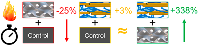
Graphical Abstract
1. INTRODUCTION
Additive manufacturing (AM) has become a major focus of both academia and industry over the past decade due partially to its promise to enable the fabrication of unique geometries that are inaccessible to other forms of manufacture (e.g., machining or injection molding).1,2 Among polymer-based forms of AM, vat photopolymerization (VP) has rapidly grown in both academic and industrial importance.3–5 Some advantages of VP include its wide array of potential chemistries (i.e., hydrogel materials, high performance engineering plastics, and so-called “4D” materials that exhibit a response to an external stimulus).6–9
One hurdle that stands between photopolymer AM and widespread industrial application is a means to reduce flammability risks that are inherent to polymeric materials.10,11 Adding to this challenge, the chemical modifiers available to reduce material flammability are becoming increasingly restrictive due to the bioaccumulation and toxicity of historically popular halogenated materials.12–14 While there are photopolymerizable nonhalogenated monomers that could be incorporated into a VP resin,15,16 incorporation of these chemistries into existing resins would require complete reformulating of every resin into which they were incorporated. Despite the commercial release of some flame retardant 3D printing resins,17,18 determining the optimal fire safety benchmarks for a VP resin is challenging because the degree of fire protection and associated test criteria are different for every application of a 3D printed part (e.g., aerospace versus automotive). The variance in requisite benchmarks has made a universally fire-safe VP resin challenging to develop.
Surface treatments have recently become popular as a means of reducing material flammability without compromising desirable mechanical characteristics or having to alter a material’s bulk composition.19–21 Among the vast amount of potential surface treatments, layer-by-layer (LbL) assembly of charged macromolecules and/or nanoparticles has received considerable attention due to its wide variety of amenable chemistries and functionalities and the fact that the coatings are deposited out of an aqueous medium at ambient conditions. With LbL’s high tunability, an immense number of reagents can be incorporated to produce a highly effective flame retardant surface treatment.22,23 Typically, flame retardant LbL coatings fall into one of two classes: intumescent (that is, based on nitrogen and phosphorus) or passive barrier coatings (typically based on clays such as vermiculite, montmorillonite, or halloysite).24–29
The thin nature of LbL films (typically <1 μm thick) favors substrate geometries with extremely high surface area, such as textiles and foams, in order to deposit enough material to provide sufficient fire protection.30,31 LbL coatings can be grown orders of magnitude thicker by manipulating charge compensation through the incorporation of salts into the coating solutions and/or rinses.25,32–34 When this technique is leveraged with so-called nanobrick wall coatings (so-named because of the highly aligned clay platelets within the coating), exceptional heat shielding performance is achieved on both polymeric and metallic substrates.35,36 To the best of our knowledge, flame retardant surface treatments have yet to be applied to 3D printed parts, especially those with complex lattice geometries.
In this work, a thick growing nanobrick wall coating of polyethylenimine (PEI) and vermiculite clay (VMT) is deposited on materials printed through vat photopolymerization, which possess complex geometries. Uncoated latticed parts failed faster in open flame testing relative to their solid counterparts. Analysis of the failed parts reveals that photopolymer printed parts preferentially fail through delamination between print layers. The preferential failure orientation is hypothesized to be a result of differential thermal expansion in the two axes of the printed parts. When coated with 8 bilayers (BL) of the PEI/VMT coating, the solid structures demonstrate negligible change in time to failure, but the lattice structures exhibit >300% improvement. This enhancement is attributed to increased surface area to volume ratio and a more flexible lattice to accommodate thermal strains. Overall, the work shows that a metamaterial combination of optimal geometry and coating offers a promising path toward general flammability protection in additively manufactured parts.
2. EXPERIMENTAL SECTION
2.1. Materials.
Branched polyethylenimine (PEI, Mw = 25,000 g mol−1), tris(hydroxymethyl) aminomethane (THAM), and phenylbis-(2,4,6-trimethylbenzoyl)phosphine oxide (BAPO, 97%) were purchased from Sigma-Aldrich (St. Louis, MO, USA). Natural vermiculite (VMT, Microlite 963++) was purchased from Specialty Vermiculite Corp. (Cambridge, MA, USA). Aqueous solutions utilized 18 MΩ deionized (DI) water. PEI containing solutions were prepared by introducing 0.1% by mass of PEI into a 50 mM THAM solution and stirring until fully dissolved. VMT suspensions were prepared as a 1% by mass aqueous solution and were rolled for 24 h to ensure homogeneity. Prior to film deposition, PEI+THAM and THAM solutions were adjusted to pH 6 with 1 M HCl (Sigma-Aldrich) and VMT solutions were adjusted to pH 10 with 1 M NaOH (Sigma-Aldrich). The acrylate-based photopolymer resin PR48 was purchased from Colorado Photopolymer Solutions (Boulder, CO, USA) in 2019.37 To facilitate faster printing (i.e., shorten layer cure times) on a 405 nm wavelength printer, the longer-wavelength photoinitiator BAPO was added to PR48 as a 0.4% by mass additive.
2.2. Part Fabrication.
All parts were printed on a Photon M3 405 nm LCD printer (Anycubic, Shenzen, China) that was measured to have an optical power output of 1.98 mW cm−2 (using a PM100D power meter, Thorlabs, Newton, NJ, USA). Computer assisted design (CAD) models of test specimens were sliced to 50 μm layers and exported as a print file in Photon Workshop (Anycubic, Shenzen, China). Prints were carried out with 4 initial “burn-in” layers with 60 s of irradiation to improve adhesion to the build plate, and all subsequent layers were printed with a 3.75 s irradiation time per layer. Between layers the build plate was lifted 6 mm at 4 mm s−1 and retracted (i.e., lowered to the new build height) at 3 mm s−1. Parts were removed from the build plate after printing and soaked 2 times in large isopropanol (IPA) baths for 15 min each, followed by drying in ambient conditions (and exposed to room lights) for 14 days prior to coating or other testing.
Parts were designed in nTopology (nTopology Inc. New York, NY, USA) (CAD) software. All triply periodic minimal surface (TPMS) gyroid structures were designed with the “Walled TPMS” function in nTopology and set to have a 500 μm wall thickness. The large gyroid cell size was set to 10 mm, while the small gyroid’s cell size was set to 5 mm. All parts were meshed and exported as Standard Tessellation Language (.stl) files with a 0.25 mm tolerance. Parts for heat shielding were 30 mm × 30 mm and latticed parts were made in a sandwich structure with a 10 mm latticed interior and a 2.5 mm solid “skin” on the large faces (for a total thickness of 15 mm). These parts were printed with handles to facilitate flame testing and dip coating. Parts for dynamic mechanical analysis (DMA), compression testing, and optical microscopy were printed without the solid “skin” structures or handles and were thus 10 mm thick. Parts for thermomechanical analysis (TMA) were solid cubes of (10 × 10 × 10) mm3. Theoretical surface areas of parts were calculated from the CAD implicit bodies using nTopology’s surface area calculation function.
2.3. Coating Deposition.
Clay nanocomposites were deposited by first introducing substrates into a pH 6 PEI+THAM solution for 5 min and were then rinsed by immersion in a pH 6, 50 mM THAM solution for 1 min. Substrates then were submerged into a pH 10 aqueous VMT dispersion for 5 min followed by a final dip rinse in pH 10 DI water for 1 min. This process completed the initial bilayer (BL), after which, all subsequent submersion times were adjusted to 1 min. This process was repeated until a total of 8 BLs were deposited. Prior to characterization, all parts were air-dried overnight, followed by additional drying at 70 °C for 24 h to expel residual water from the coating process.
2.4. Open Flame Testing.
All substrates were tested under identical conditions. Coated and uncoated substrates were held with a clamp in a ring stand to center the largest face of the printed part toward the butane torch (Bernzomatic ST2200, Worthington Industries, Columbus, OH, USA). The torch nozzle was positioned 2 cm away from the center of the part with the deep blue inner cone of the flame adjusted to a length of 2 cm. Parts were subjected to direct flame exposure until failure, which was defined to be when the part visually fractured from the heat. This fracture typically led to a large piece of the part separating from the specimen and falling to the benchtop. After failure, parts were allowed to continue burning until either the part was consumed or the flame naturally burned out.
2.5. Thermal and Mechanical Characterization.
An uncoated solid part printed from the 0.4% by mass BAPO in PR48 was subjected to thermogravimetric analysis (TGA) utilizing a Q50 Thermogravimetric Analyzer (TA Instruments, New Castle, DE, USA). A part shard weighing 6.3 mg was heated isothermally at 100 °C for 20 min to remove any residual moisture; then the temperature was increased by 10 °C min−1 up to 700 °C under a 60 mL min−1 flow of air. In addition to TGA, an uncoated cube printed from the 0.4% by mass BAPO in PR48 was subjected to thermomechanical analysis (TMA), using a Q400 Thermomechanical Analyzer (TA Instruments, New Castle, DE, USA). Cubes were subjected to a constant force of 0.5 N as the temperature ramped at a rate of 2 °C min−1 up to 200 °C, at which point the temperature was maintained for 10 min. Dynamic mechanical analysis (DMA) under increasing temperature was performed on a Q800 Dynamic Mechanical Analyzer (TA Instruments, New Castle, DE, USA), with a 15 μm compressive oscillation amplitude at 1 Hz. In this experiment, samples were equilibrated at 35 °C for 5 min before a 2 °C min−1 temperature ramp to 350 °C under air. Compressive modulus was determined by subjecting both uncoated and coated parts to compression between two 25 mm cylinders affixed to an 858 mini Bionix II load frame (MTS, Eden Prairie, MN, USA) with a 12 kN load cell. Samples were compressed at a uniform rate of 1 mm s−1. Collected force and displacement data were utilized to determine compressive modulus from the first 1% of compressive strain in each sample. Optical micrographs were taken on a VHX 600 microscope (Keyence, Osaka, Japan). To elucidate areal coverage of coatings, some images were collected under illumination from a combination of the microscope’s white light and a 370 nm UV flashlight mounted on a ring stand and pointed toward the sample. These images with combined illumination were all collected without adjusting the light intensity or direction between samples.
3. RESULTS AND DISCUSSION
3.1. Additively Manufactured Parts.
A rendered CAD model along with photographs of the printed parts are shown in Figure 1. Additionally, these samples were printed with a handle to facilitate the dip coating procedure. The parts were printed with three different core structures, which are denoted as solid (100% infill), small gyroid (a gyroid lattice structure with a 5 mm cell size in all dimensions), and large gyroid (a gyroid lattice structure with 10 mm cells). These structures were chosen to gain an understanding of the influence of surface area on part flammability and mechanical strength and the employed coating’s effect. It can be seen from Figure 1c–e that there is a residual yellow color in the solid parts that is not present in the gyroid structures. This color is likely from unreacted BAPO and is more apparent in the thicker parts because of their longer optical path length.
Figure 1.
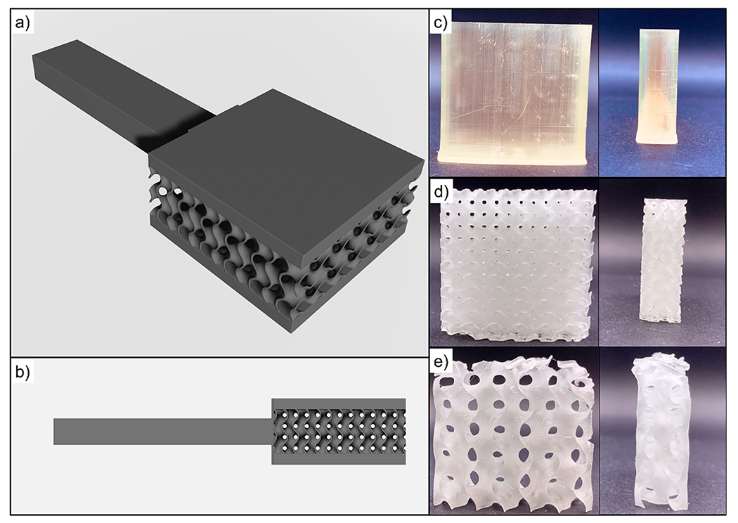
CAD models of small gyroid parts with exterior skin for coating and fire testing (a,b). Photographs of “skinless” models for other characterization: solid (c), small gyroid (d), and large gyroid (e).
Theoretical surface area for the input models, and normalized mass for the models and printed parts, are provided in Table 1. Comparison between theoretical mass ratios (inferred from the theoretical volume provided by slicing software) and measured mass ratios allows inference of overpolymerization or underpolymerization of the resultant parts. Mass ratios in Table 1 are normalized to the mass of the solid part. Inspection of Table 1 suggests that the gyroid parts are underpolymerized relative to the solid part, by as much as 30% in the case of the large gyroid with no skin. The skinless solid blocks for DMA analysis were determined to have a final printed volume of 8.8 ± 0.1 cm3 by measuring with calipers. The discrepancy in printed volume versus the programmed volume of 9.0 cm3 can be attributed to part shrinkage. During printing, the solid parts have an uninterrupted projection footprint, which may create more local heating to drive the curing process forward and lead to adequately polymerized regions of illumination.38 In the case of the gyroid systems, the projected light density is significantly lower. Inspection of the individual image stacks for the gyroid prints reveals that at their thinnest point, the gyroid walls are just 4 pixels thick (ca. 160 μm). The cross-sectional area illuminated in vat photopolymerization has previously been shown to affect the mechanical properties of the printed region, which is assumed to be a result of less monomer conversion.39 It is possible that the thin walls of the gyroid projections are particularly underpolymerized and responsible for the lower apparent density of the parts.
Table 1.
Calculated Surface Area, Theoretical Mass Ratio, Measured Mass Ratio, and Coating Weight Gains for Skinless Structures
| Geometry | Theoretical surface area (mm2) | Theoretical Mass/Solid Mass | Measured Mass/Solid Mass | % mass increase by coating |
|---|---|---|---|---|
| Solid | 3,000 | 1.00 | 1.00 | 0.14 ± 0.03 |
| Small Gyroid | 11,000 | 0.19 | 0.14 | 4.9 ± 1.3 |
| Large Gyroid | 9,700 | 0.10 | 0.07 | 4.73 ± 0.52 |
3.2. Nanobrick Wall Deposition.
To minimize the number of processing steps to deposit a coating, a thickgrowing LbL system comprised of PEI+THAM and VMT was employed. Traditional LbL systems (i.e., not thick-growing) deposit anywhere from 3 to 10 nm of material per BL and therefore require too many bilayers or a high surface area substrate to provide sufficient properties.30,31 Through the incorporation of THAM into the cationic coating and rinse solutions, the coating materials’ charge compensation is manipulated to obtain much thicker growth.25,32–34 Furthermore, the pH of these solutions can be adjusted to increase the ionic strength of the solutions that, in combination with THAM’s inclusion in the cationic solution and rinse, yields a coating that grows >60 times thicker than PEI/VMT on their own.30,35 In the case of this polymer/clay system, the introduction of THAM causes several platelets to stack onto one another and be deposited in a single BL.35 The schematic shown in Figure 2 summarizes the layer-by-layer deposition process.
Figure 2.
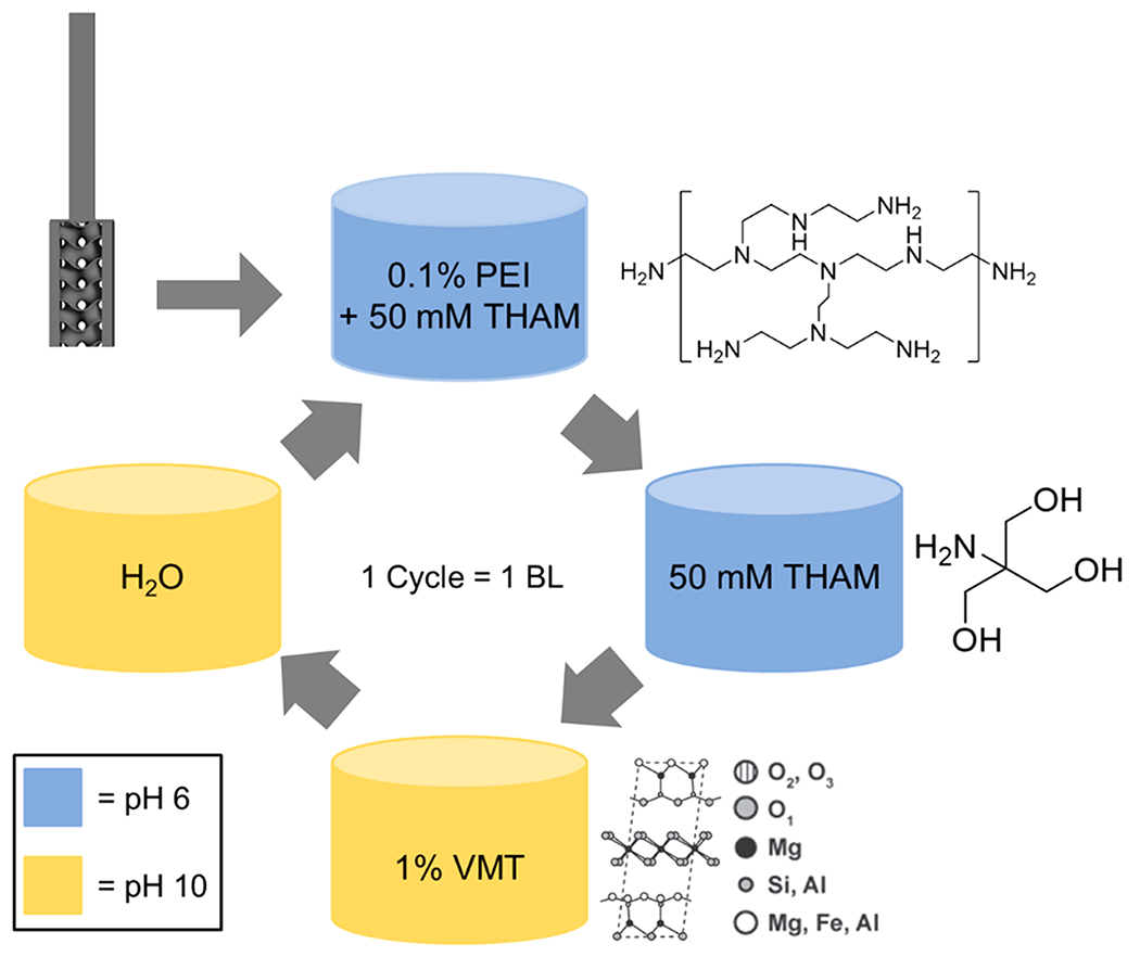
Schematic of coating deposition and coating materials. Samples coated with 8 BLs are studied in this work.
After coating deposition, the weight added to the parts was tabulated. It was observed that the solid parts with a skin demonstrated the lowest weight gain of 0.40% by mass, whereas the weight of the small and large gyroids increased 1.57% by mass and 1.2% by mass, respectively. An increase in weight gain compared to the solid parts was expected, as both of the gyroid structures have a significantly (>3×) higher surface area, allowing for a higher degree of coating deposition. Due to the large gyroid’s cavity size, there was sufficient spacing between each cell for full solution infiltration and a more uniform growth of the coating. Despite having a larger programmed interior surface area than the large gyroid (Table 1), the small gyroid exhibited only a slightly larger weight gain when compared to the large gyroid. Air bubbles were observed in the small gyroids during both the postprint IPA rinses and during coating application, suggesting that some fraction of the interior of the part was not exposed to the coating solution and therefore a smaller weight gain was achieved. The consequences of this are shown in Figure 3, which shows photographs of the coated parts.
Figure 3.
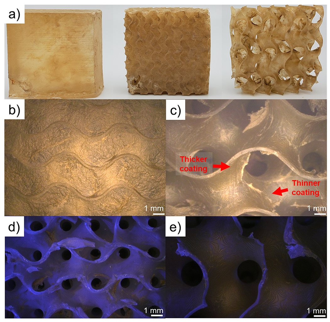
Photographs of coated parts (a) from left to right: solid, small gyroid, and large gyroid. Optical micrographs of the exterior of a coated small gyroid, which has had its pores blocked by the thick growth of the nanobrick wall coating (b), exterior of a coated large gyroid (c). Optical micrographs under a combination of UV and white light illumination of: a cross-section of a coated small gyroid (d) and a cross-section of a coated large gyroid (e). Regions without fluorescence under UV light are attributed to the nanobrick wall coating. The large amount of fluorescence in part (d) highlights that very little coating penetrates to the interior of the small gyroid, while part (e) shows complete coverage of all surfaces.
The much smaller pore sizes of the small gyroid, as well as the exponential growth profile of the coating, prevents full infiltration of the part by the coating/rinse solutions.35 Additionally, the coating is highly hygroscopic while it grows. Despite drying to around 3 μm thick, the water-swollen PEI+THAM/VMT coating during the deposition process is visibly thicker than 1 mm because of its large water uptake. Microscopy of the coated gyroid parts show that the pores of the small gyroid are completely covered by the coating (Figure 3b), suggesting that the very thick growth of the coating prevents mass transport to the interior of the small gyroid. Meanwhile, the large gyroid shows open pores and coating on the interior of the part is clearly visible (Figure 3c). There are some imperfections in the coating on the large gyroid that are visible under an optical microscope, where some areas have extra coating and others have visibly thinner coatings. These imperfections are likely artifacts of the drying process of the hygroscopic coating.
To probe the extent of coating infiltration, optical microscopy of cross sections of coated small and large gyroids were obtained under illumination from a combination of UV light and white light (Figure 3d,e). The photoblocker present in PR48, 2,5-Bis(5-tert-butyl-benzoxazol-2-yl)thiophene (BBOT), is a well-known fluorescent molecule and causes PR48 parts to fluoresce under ultraviolet irradiation.40 The presence of coating suppresses the fluorescence (micrographs of the exterior of coated and uncoated parts under the same illumination conditions are shown in Figure S1), so lack of fluorescence indicates coverage by the coating. It is clear from studying Figure 3d,e that there is less suppression of PR48’s fluorescence on the interior of the small gyroid as compared to the large gyroid (which only fluoresces where the coated part was cut). This indicates poor infiltration of the coating, as expected by the blocked pores, shown in Figure 3b. Future lattice designs seeking to optimize conformal coating should consider flow and wetting in their design, especially as lattice dimensions are reduced.
3.3. Flammability Testing.
After coating deposition, coated and uncoated parts were subjected to fire testing utilizing a butane torch positioned 2 cm away from the samples. Digital images of the testing setup can be seen in Figure S2. All samples were exposed to the butane flame until part failure, which is defined as when the face exposed to the flame visibly fractured and a piece of the part fell onto the benchtop. Parts were observed to experience preferential failure between print layers. Elapsed time between the flame impinging on the sample and the sample undergoing visible fracture is denoted as the Time to Failure (TtF). Solid blocks in particular tended to split with enough force that the separated piece ricocheted off of the fume hood sash into the back of the hood. A series of photographs shown in Figure 4 illustrate the results of the flame testing process for selected replicates of the coated and uncoated parts. Among the uncoated parts, the solid parts take the longest time to fail, with a TtF of 70 s, whereas the uncoated small and large gyroids have TtFs of ≈50 s. The presence of the internal gyroid appears to adversely decrease the TtF, possibly owing to the increased internal surface area and lower initial part weight. The greater surface area is evident when watching flame tests because the gyroid parts visibly produce more smoke during torch testing (videos of open flame tests are provided in Supporting Information).
Figure 4.
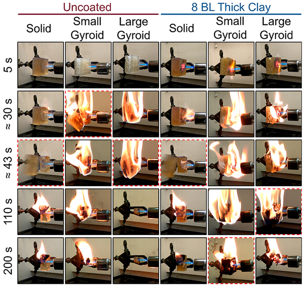
Time series photographs of torch testing the coated and uncoated samples of varying print geometry. Failure events are indicated by red dashed borders.
The coated solid parts displayed little improvement over their uncoated counterparts in terms of time to failure. This is likely due to the low weight gain (0.40%) and the amount of uncoated material available for burning and thermal expansion underneath the coating. The coated small and large gyroid parts displayed larger TtF increases of 246% and 338%, respectively, compared to their uncoated analogues. This drastic increase is attributed to the higher surface area and greater extent of the coating throughout the interior of the parts. This was accomplished through the inclusion of the internal gyroid structure that both increases the available surface for coating deposition and may provide thermal flexibility, which ultimately allows for a higher degree of flame retardancy than the solid part.41 This demonstrates for the first time a powerful synergy between the latticing capability enabled by additive manufacturing and the growing popularity of conformal flame retardant surface coatings. Uncoated latticed structures failed significantly faster than the solid parts, but the same surface area that made them more susceptible to burning also led to a longer TtF in the coated system. This opens the door to a potentially vast landscape of 3D printed metamaterials making use of LbL’s numerous application spaces. An example use case would be the application of a gyroid structure to a printed object (e.g., an electrical connector for the automotive industry) to simultaneously reduce the weight of the object and provide a high surface area with which to deposit a coating and reduce the system’s fire hazard. However, a more robust understanding of the interplay between gyroid cell size and material flammability will have to be developed before the ideal of metamaterials can be realized.
The “thick clay” coating provides fire protection to the system due to its high inorganic content (>80% by mass) and the presence of THAM and PEI.36 It is well established that THAM and PEI both degrade when exposed to high temperatures, yielding significant amounts of nonflammable gases (e.g., nitrogen, water, and carbon dioxide).25,36 These gases expand the VMT platelet layers, effectively creating a heat shielding bubble (Figure S3). The ceramic and gas shell exhibits low thermal conductivity and protects the unburned part (dramatically increasing its TtF). Table 2 provides coating mass gains as well as torch testing results with corresponding uncertainties.
Table 2.
Coating Weight Gains and Torch Testing Data for Printed Parts (Uncertainties Eaual ±1 Standard Deviation)
| Sample | Coating Mass Gain(%) | Uncoated TtF(s) | Coated TfT(s) | TtF Increase |
|---|---|---|---|---|
| Solid | 0.40 ± 0.12 | 68 ± 20 | 70 ± 22 | +3% |
| Small Gyroid | 1.57 ± 0.39 | 51 ± 13 | 176 ± 54 | +246% |
| Large Gyroid | 1.2 ± 0.5 | 50 ± 9 | 217 ± 100 | +338% |
Surprisingly, the printed photopolymer does not drip when exposed to fire. Dripping occurs due to thermal degradation depolymerizing a material back to a low viscosity oligomer/monomer, which will freely flow or drip and can create a pool fire underneath the original burning item and leads to rapid flame spread.42 DMA experiments were done on solid blocks to determine the glass transition temperature (Tg) for PR48. A representative DMA trace is shown in Figure S4 and the peak of tan(δ) indicates a Tg of ≈85 °C. However, there is no melting transition visible from these data. In fact, rather than melting, the PR48 significantly charred during the DMA experiments (images of the part after DMA testing are shown in Figure S5). The heavy cross-linking (via charring) of the fire-exposed exterior of the part renders it incapable of melting.19 Thermal expansion stresses coupled with the charred exterior are the proposed reason that the PR48 monoliths cracked and, in the case of the solid parts, split into two separate pieces during flame exposure.
Optical micrographs of both an unburned solid part and two burned solid parts that exhibited different failure modes (i.e., interlayer or intralayer) are provided in Figure 5. Interlayer failure (i.e., on the xy-plane, Figure 5b) is when the part fractured in between two print layers, whereas intralayer failure (z-axis failure in Figure 5c) is when the part fractured perpendicular to the print lines. Large gaps appear between layers after flame testing, regardless of the orientation of the part failure (this is also seen in the charred part in Figure S5). Interlayer adhesion is a near-universal problem faced by all forms of additive manufacturing, which degrades mechanical strength and gives rise to part anisotropy.37,43 These results suggest that the effect and directionality of layering should be considered when engineering 3D printed parts for environments that face either thermal stress or direct fire risk.
Figure 5.
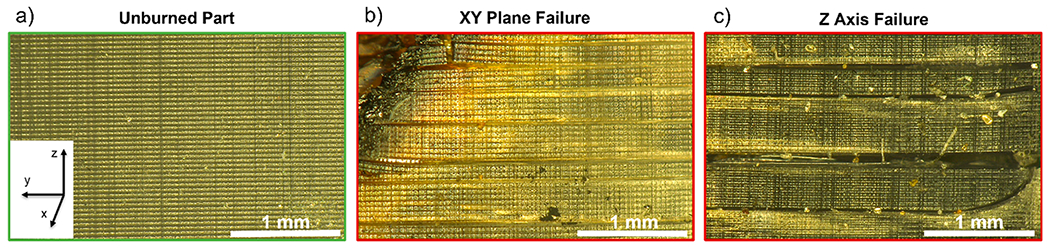
Optical micrographs of an unburned solid part (a) and two burned solid parts, which experienced different failure modes through the xy-plane (b) or the z-axis (c). Failure axes are defined as relative to the printing process (where the z axis is defined as the one along which the build plate moves.
As previously mentioned, PR48 forms char when heated rather than melting, which limits flexibility for the part to accommodate thermal stress. The monoliths preferentially fracture under the applied stress. This fracturing of all parts occurs primarily (but not exclusively) at the interface between print layers. This preference for interlayer failure likely occurs due to the conversion and stiffness gradients in most VP parts across printed layers.37,43 To investigate this thermally induced fracturing, uncoated parts were subjected to TGA and TMA. TGA was utilized to identify the degradation temperature of the uncoated parts, which is defined as when the sample mass decreases approximately 5%, excluding the mass loss induced by water or solvent evaporation. The uncoated PR48’s’s degradation temperature was determined to be 312 °C (denoted by the star in Figure 6a). This is a relatively high temperature for the onset of degradation for a polymeric material. Thermoplastics such as poly(methyl methacrylate), as well as thermosets like polyurethane foam have significantly lower degradation temperatures than the studied PR48 resin, despite being an acrylate-based resin.37,44,45 This is likely due to SR 494 being incorporated into PR48. SR 494 is a derivative of pentaerythritol, a known flame retardant and char promoter.46
Figure 6.
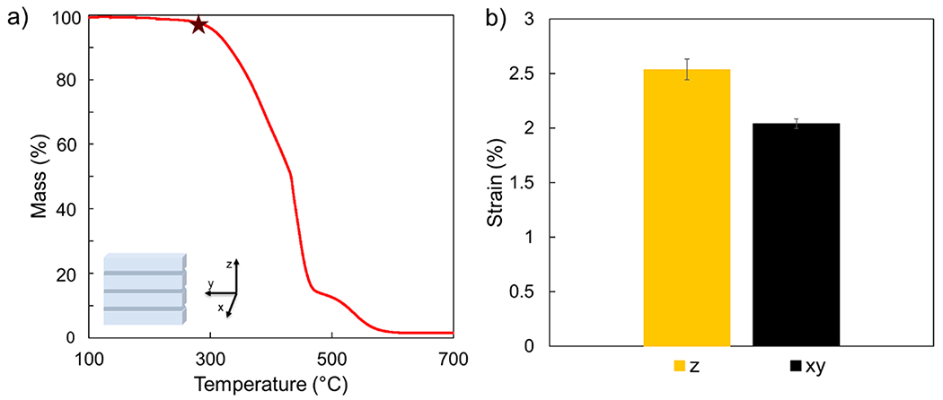
TGA from an uncoated part, as well as a coordinate depiction of the 3D printed part. The maroon star depicts the degradation temperature of the part (312 °C) (a). Percent strain vs testing orientation for uncoated PR48 parts, following a 200 °C isotherm in both interlayer (z) and intralayer (xy) orientations (b).
Uncoated cubes were subjected to TMA to probe their thermally induced strain in both the nonprint line (z) and print line (x–y) axes. The thermally induced strain in both print line and nonprint line direction provided insight as to why the parts had a preference to fracture between layers. A constant force of 0.5 N was applied to the parts as the temperature was ramped at a rate of 2 °C min−1 up to 200 °C, at which point the temperature was held constant for 10 min. The strain was measured at the end of this isothermal hold. The ceiling temperature was set at 200 °C to avoid material degradation (i.e., polymer decomposition or charring). The thermal expansion (strain) in the z axis was 2.5%, whereas the strain in the xy-plane was 2%. This difference in thermal expansion is consistent with the preferential orientation of part failure that was noted during torch testing. Inhomogeneity of elastic modulus of printed parts through the z-axis has been previously demonstrated and is presumed to be a result of unequal conversion throughout a layer.37,44,45,47 It has previously been shown in other cross-linked networks that thermal expansion changes as a function of conversion.48 The poor interlayer adhesion, paired with the unequal thermal stresses, is a plausible culprit for the preferential orientation of printed part failure.
3.4. Mechanical Testing.
The compressive modulus of each printed part was measured to evaluate the influence of the coating on the mechanical properties of a 3D printed part. The resultant compressive moduli for both uncoated and coated parts are summarized in Figure 7. As expected, the solid part had the highest compressive modulus, followed by the small gyroid and then the large gyroid. The error bars in Figure 7 make it clear that the relative uncertainty in the modulus was significantly larger for the small gyroid. The greater uncertainty likely reflects the greater sensitivity of this particular structure to overpolymerization or underpolymerization. LCD printers, such as the one used in this study, are known to have nonuniform light engines, which can lead to “bright spots” of higher light intensity and “dark spots” of lower light intensity.49 In the case of the small gyroid structure, an overpolymerization event could lead to a solid region where there is supposed to be a cavity, or a larger cell than is designed in the CAD file.
Figure 7.
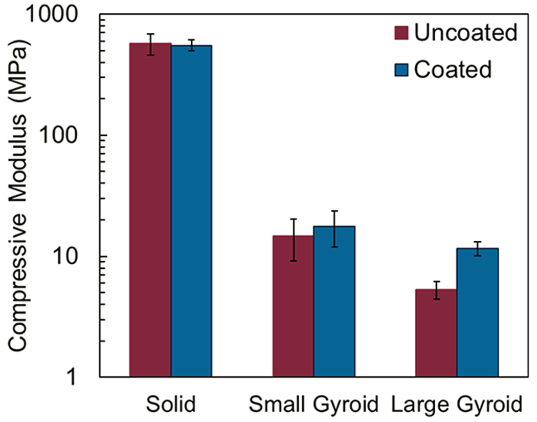
Compressive modulus of the uncoated and coated parts.
The presence of the coating seems to have a negligible influence on the stiffness of the solid and the small gyroid parts, with both coated and uncoated systems showing overlapping error bars. Despite the high mechanical strength of the nanobrick layers, a negligible effect is expected for the solid part because of the relatively small to the total part volume. As discussed earlier, the coating process could not uniformly coat the interior of the small gyroid, limiting any stiffening effect of the coating. In contrast, the large gyroid shows a clear increase in modulus after coating. This is because the large gyroid has the largest accessible surface area. As such, the part can be uniformly coated, increasing the bending moment of inertia of the struts. Since modulus values were calculated from the early phase of compression, initial buckling of the structure was mitigated by the presence of the coating and as such a significant increase in modulus was observed.
4. CONCLUSION
This study analyzed the effectiveness of a nanobrick wall coating and latticed structuring for flame retarding vat photopolymerization 3D printed parts. It was found that introducing latticed geometries to uncoated parts led to a faster time to failure, possibly owing to lower initial part weight (i.e., less material to burn) and higher surface area for combustion. Solid parts with and without coating experienced little to no change in time to failure (≈70 s) and mechanical properties, which is attributed to the relatively low weight added (0.40 % by mass) by the coating. However, nanobrick coated latticed structures, only 1% heavier than uncoated analogues, exhibited a significant increase in time to failure (up to ≈340%) compared to uncoated latticed parts. For the large gyroid lattice, the coating also led to improved mechanical properties. The synergistic effect of latticing and coating is attributed to both the lattice structures’ increased surface area to volume ratio and the conformal nature of the deposited coating, both allowing for increased coating to polymer ratio. This synergistic effect also allows for the latticed parts to better accommodate thermal strains. Future coating+lattice codesign affords considerable opportunity for optimization of wetting chemistry, processing and part geometry, wherein even small regions of coated latticing might mitigate flammability of complex parts.
Supplementary Material
ACKNOWLEDGMENTS
This work was performed while Thomas Kolibaba held a National Research Council Associateship Award at the National Institute of Standards and Technology (NIST). The use of Texas A&M Mechanical Engineering’s Shared Services Laboratory is acknowledged. Certain commercial equipment, instruments, or materials are identified in this paper to specify the experimental procedure adequately. Such identification is not intended to imply recommendation or endorsement by NIST.
Footnotes
Supporting Information
The Supporting Information is available free of charge at https://pubs.acs.org/doi/10.1021/acsami.3c00177.
A link to NIST-hosted videos of fire tests and. STL files, along with Figures S1–S5 (PDF)
Complete contact information is available at: https://pubs.acs.org/10.1021/acsami.3c00177
The authors declare no competing financial interest.
Contributor Information
Thomas J. Kolibaba, Applied Chemicals and Materials Division, National Institute of Standards and Technology, Boulder, Colorado 80305, United States.
Ethan T. Iverson, Department of Chemistry, Texas A&M University, College Station, Texas 77843, United States.
Hudson Legendre, Department of Mechanical Engineering, Texas A&M University, College Station, Texas 77843, United States.
Callie I. Higgins, Applied Chemicals and Materials Division, National Institute of Standards and Technology, Boulder, Colorado 80305, United States
Zachary N. Buck, Applied Chemicals and Materials Division, National Institute of Standards and Technology, Boulder, Colorado 80305, United States
Timothy S. Weeks, Applied Chemicals and Materials Division, National Institute of Standards and Technology, Boulder, Colorado 80305, United States
Jaime C. Grunlan, Department of Chemistry, Texas A&M University, College Station, Texas 77843, United States; Department of Materials Science and Engineering and Department of Mechanical Engineering, Texas A&M University, College Station, Texas 77843, United States
Jason P. Killgore, Applied Chemicals and Materials Division, National Institute of Standards and Technology, Boulder, Colorado 80305, United States
REFERENCES
- (1).Vafadar A; Guzzomi F; Rassau A; Hayward K Advances in Metal Additive Manufacturing: A Review of Common Processes, Industrial Applications, and Current Challenges. Applied Sciences 2021, 11 (3), 1213. [Google Scholar]
- (2).Saleh Alghamdi S; John S; Roy Choudhury N; Dutta NK Additive Manufacturing of Polymer Materials: Progress, Promise and Challenges. Polymers 2021, 13 (5), 753. [DOI] [PMC free article] [PubMed] [Google Scholar]
- (3).Crivello JV; Reichmanis E Photopolymer Materials and Processes for Advanced Technologies. Chem. Mater 2014, 26 (1), 533–548. [Google Scholar]
- (4).Appuhamillage GA; Chartrain N; Meenakshisundaram V; Feller KD; Williams CB; Long TE 110th Anniversary : Vat Photopolymerization-Based Additive Manufacturing: Current Trends and Future Directions in Materials Design. Ind. Eng. Chem. Res 2019, 58 (33), 15109–15118. [Google Scholar]
- (5).Bagheri A; Jin J Photopolymerization in 3D Printing. ACS Appl. Polym. Mater 2019, 1 (4), 593–611. [Google Scholar]
- (6).Wang Y; Alizadeh N; Barde M; Auad ML; Beckingham BS Poly(Acrylic Acid)-Based Hydrogel Actuators Fabricated via Digital Light Projection Additive Manufacturing. ACS Appl. Polym. Mater 2022, 4, 971. [Google Scholar]
- (7).Arrington CB; Hegde M; Meenakshisundaram V; Dennis JM; Williams CB; Long TE Supramolecular Salts for Additive Manufacturing of Polyimides. ACS Appl. Mater. Interfaces 2021, 13 (40), 48061–48070. [DOI] [PubMed] [Google Scholar]
- (8).Schwartz JJ; Boydston AJ Multimaterial Actinic Spatial Control 3D and 4D Printing. Nat. Commun 2019, 10, 791. [DOI] [PMC free article] [PubMed] [Google Scholar]
- (9).Andreu A; Su P-C; Kim J-H; Ng CS; Kim S; Kim I; Lee J; Noh J; Subramanian AS; Yoon Y-J 4D Printing Materials for Vat Photopolymerization. Additive Manufacturing 2021, 44, 102024. [Google Scholar]
- (10).Levchik SV Introduction to Flame Retardancy and Polymer Flammability. In Flame Retardant Polymer Nanocomposites, Morgan AB; Wilkie Charles, A., Eds.; Wiley & Sons, 2007. [Google Scholar]
- (11).Morgan AB; Wilkie CA An Introduction to Polymeric Flame Retardancy, Its Role in Materials Science, and the Current State of the Field. In Fire Retardancy of Polymeric Materials, Morgan AB; Wilkie CA, Eds.; CRC Press, 2010; pp 1–14. [Google Scholar]
- (12).de Wit CA An Overview of Brominated FLame Retardants in the Environment. Chemosphere 2002, 46, 583. [DOI] [PubMed] [Google Scholar]
- (13).Kim YR; Harden FA; Toms L-ML; Norman RE Health Consequences of Exposure to Brominated Flame Retardants: A Systematic Review. Chemosphere 2014, 106, 1–19. [DOI] [PubMed] [Google Scholar]
- (14).Lyche JL; Rosseland C; Berge G; Polder A Human Health Risk Associated with Brominated Flame-Retardants (BFRs. Environ. Int 2015, 74, 170–180. [DOI] [PubMed] [Google Scholar]
- (15).Zhou B; Yang M; Zuo C; Chen G; He D; Zhou X; Liu C ; Xie X; Xue Z Flexible, Self-Healing, and Fire-Resistant Polymer Electrolytes Fabricated via Photopolymerization for All-Solid-State Lithium Metal Batteries. ACS Macro Lett. 2020, 9, 525–532. [DOI] [PubMed] [Google Scholar]
- (16).Kolibaba TJ; Vest NA; Grunlan JC Polyelectrolyte Photopolymer Complexes for Flame Retardant Wood. Mater. Chem. Front 2022, 6, 1630–1636. [Google Scholar]
- (17).Petch M The State of Resin 3D Printing: David Walker, Co-Founder Azul 3D & Northwestern University Researcher; 3D Printing Industry. https://3dprintingindustry.com/news/the-state-of-resin-3d-printing-david-walker-co-founder-azul-3d-northwestern-university-researcher-203502/ (accessed 2022–07–11).
- (18).Carbon Unveils Flame-Retardant Photopolymer Resin for 3D Printing; Plastics Today: Community for Plastics Professionals. https://www.plasticstoday.com/automotive-and-mobility/carbon-unveils-flame-retardant-photopolymer-resin-3d-printing (accessed 2022–07–11).
- (19).Lazar ST; Kolibaba TJ; Grunlan JC Flame-Retardant Surface Treatments. Nat. Rev. Mater 2020, 5 (4), 259–275. [Google Scholar]
- (20).Morgan AB The Future of Flame Retardant Polymers – Unmet Needs and Likely New Approaches. Polym. Rev 2019, 59 (1), 25–54. [Google Scholar]
- (21).Liu B-W; Zhao H-B; Wang Y-Z Advanced Flame-Retardant Methods for Polymeric Materials. Adv. Mater 2022, 34, 2107905. [DOI] [PubMed] [Google Scholar]
- (22).Holder KM; Smith RJ; Grunlan JC A Review of Flame Retardant Nanocoatings Prepared Using Layer-by-Layer Assembly of Polyelectrolytes. J. Mater. Sci 2017, 52 (22), 12923–12959. [Google Scholar]
- (23).Qiu X; Li Z; Li X; Zhang Z Flame Retardant Coatings Prepared Using Layer by Layer Assembly: A Review. Chem. Eng. J 2018, 334, 108–122. [Google Scholar]
- (24).Li Y-C; Mannen S; Morgan AB; Chang S; Yang Y-H; Condon B; Grunlan JC Intumescent All-Polymer Multilayer Nanocoating Capable of Extinguishing Flame on Fabric. Adv. Mater 2011, 23 (34), 3926–3931. [DOI] [PubMed] [Google Scholar]
- (25).Lazar S; Eberle B; Bellevergue E; Grunlan J Amine Salt Thickening of Intumescent Multilayer Flame Retardant Treatment. Ind. Eng. Chem. Res 2020, 59 (7), 2689–2695. [Google Scholar]
- (26).Jordanov I; Magovac E; Fahami A; Lazar S; Kolibaba T; Smith RJ; Bischof S; Grunlan JC Flame Retardant Polyester Fabric from Nitrogen-Rich Low Molecular Weight Additives within Intumescent Nanocoating. Polym. Degrad. Stab 2019, 170, 108998. [Google Scholar]
- (27).Holder KM; Huff ME; Cosio MN; Grunlan JC Intumescing Multilayer Thin Film Deposited on Clay-Based Nanobrick Wall to Produce Self-Extinguishing Flame Retardant Polyurethane. J. Mater. Sci 2015, 50 (6), 2451–2458. [Google Scholar]
- (28).Laufer G; Kirkland C; Cain AA; Grunlan JC Clay–Chitosan Nanobrick Walls: Completely Renewable Gas Barrier and Flame-Retardant Nanocoatings. ACS Appl. Mater. Interfaces 2012, 4 (3), 1643–1649. [DOI] [PubMed] [Google Scholar]
- (29).Smith RJ; Holder KM; Ruiz S; Hahn W; Song Y; Lvov YM; Grunlan JC Environmentally Benign Halloysite Nanotube Multilayer Assembly Significantly Reduces Polyurethane Flammability. Adv. Funct. Mater 2018, 28 (27), 1703289. [Google Scholar]
- (30).Lazar S; Carosio F; Davesne A-L; Jimenez M; Bourbigot S; Grunlan J Extreme Heat Shielding of Clay/Chitosan Nanobrick Wall on Flexible Foam. ACS Appl. Mater. Interfaces 2018, 10 (37), 31686–31696. [DOI] [PubMed] [Google Scholar]
- (31).Magovac E; Vončina B; Budimir A; Jordanov I; Grunlan JC; Bischof S Environmentally Benign Phytic Acid-Based Nanocoating for Multifunctional Flame-Retardant/Antibacterial Cotton. Fibers 2021, 9 (11), 69. [Google Scholar]
- (32).Apaydin K; Laachachi A; Ball V; Jimenez M; Bourbigot S; Toniazzo V; Ruch D Polyallylamine–Montmorillonite as Super Flame Retardant Coating Assemblies by Layer-by Layer Deposition on Polyamide. Polym. Degrad. Stab 2013, 98 (2), 627–634. [Google Scholar]
- (33).Guin T; Krecker M; Hagen DA; Grunlan JC Thick Growing Multilayer Nanobrick Wall Thin Films: Super Gas Barrier with Very Few Layers. Langmuir 2014, 30 (24), 7057–7060. [DOI] [PubMed] [Google Scholar]
- (34).Laachachi A; Ball V; Apaydin K; Toniazzo V; Ruch D Diffusion of Polyphosphates into (Poly(Allylamine)-Montmorillonite) Multilayer Films: Flame Retardant-Intumescent Films with Improved Oxygen Barrier. Langmuir 2011, 27 (22), 13879–13887. [DOI] [PubMed] [Google Scholar]
- (35).Guin T; Krecker M; Milhorn A; Hagen DA; Stevens B; Grunlan JC Exceptional Flame Resistance and Gas Barrier with Thick Multilayer Nanobrick Wall Thin Films. Advanced Materials Interfaces 2015, 2 (11), 1500214. [Google Scholar]
- (36).Long CT; Wang R; Shoalmire C; Antao DS; Shamberger PJ; Grunlan JC Efficient Heat Shielding of Steel with Multilayer Nanocomposite Thin Film. ACS Appl. Mater. Interfaces 2021, 13 (16), 19369–19376. [DOI] [PubMed] [Google Scholar]
- (37).Gojzewski H; Guo Z; Grzelachowska W; Ridwan MG; Hempenius MA; Grijpma DW; Vancso GJ Layer-by-Layer Printing of Photopolymers in 3D: How Weak Is the Interface? ACS Appl. Mater. Interfaces 2020, 12 (7), 8908–8914. [DOI] [PMC free article] [PubMed] [Google Scholar]
- (38).Jiang F; Drummer D Curing Kinetic Analysis of Acrylate Photopolymer for Additive Manufacturing by Photo-DSC. Polymers 2020, 12 (5), 1080. [DOI] [PMC free article] [PubMed] [Google Scholar]
- (39).Higgins CI; Brown TE; Killgore JP Digital Light Processing in a Hybrid Atomic Force Microscope: In Situ, Nanoscale Characterization of the Printing Process. Additive Manufacturing 2021, 38, 101744. [DOI] [PMC free article] [PubMed] [Google Scholar]
- (40).Tury G; Vabrik R Enhancement of Fluorescent Stability of 2,5-Bis-2- (Stert-Butyl) - Benzoxazolyl-Thiophene (BBOT) Containing LDPE Films. J. Photochem. Photobiol., A 1998, 114, 51–58. [Google Scholar]
- (41).Khaderi SN; Deshpande VS; Fleck NA The Stiffness and Strength of the Gyroid Lattice. International Journal of Solids and Structures 2014, 51 (23–24), 3866–3877. [Google Scholar]
- (42).Matzen M; Kandola B; Huth C; Schartel B Influence of Flame Retardants on the Melt Dripping Behaviour of Thermoplastic Polymers. Materials 2015, 8 (9), 5621–5646. [DOI] [PMC free article] [PubMed] [Google Scholar]
- (43).Uzcategui AC; Higgins CI; Hergert JE; Tomaschke AE; Crespo-Cuevas V; Ferguson VL; Bryant SJ; McLeod RR; Killgore JP Microscale Photopatterning of Through-Thickness Modulus in a Monolithic and Functionally Graded 3D-Printed Part. Small Science 2021, 1 (3), 2000017. [DOI] [PMC free article] [PubMed] [Google Scholar]
- (44).Vest NA; Kolibaba TJ; Afonso AO; Kulatilaka SA; Iverson ET; Grunlan JC Acid-Doped Biopolymer Nanocoatings for Flame-Retardant Polyurethane Foam. ACS Appl. Polym. Mater 2022, 4 (3), 1983–1990. [Google Scholar]
- (45).Guan X; Ma X; Zhou H; Chen F; Li Z Synthesis and Thermal Decomposition Kinetics of Poly(Methyl Methacrylate)- b-Poly(Styrene) Block Copolymers. Journal of Thermoplastic Composite Materials 2017, 30 (5), 691–706. [Google Scholar]
- (46).Gu J; Zhang G; Dong S; Zhang Q; Kong J Study on Preparation and Fire-Retardant Mechanism Analysis of Intumescent Flame-Retardant Coatings. Surf. Coat. Technol 2007, 201 (18), 7835–7841. [Google Scholar]
- (47).Zhao Z; Wu D; Chen H-S; Jerry Qi H; Fang D Indentation Experiments and Simulations of Nonuniformly Photo-crosslinked Polymers in 3D Printed Structures. Additive Manufacturing 2020, 35, 101420. [Google Scholar]
- (48).Leroy E; Dupuy J; Maazouz A; Seytre G Evolution of the Coefficient of Thermal Expansion of a Thermosetting Polymer during Cure Reaction. Polymer 2005, 46 (23), 9919–9927. [Google Scholar]
- (49).Caplins BW; Higgins CI; Kolibaba TJ; Arp U; Miller CC; Poster DL; Zarobila CJ; Zong Y; Killgore JP Characterizing Light Engine Uniformity and Its Influence on Liquid Crystal Display Based Vat Photopolymerization Printing. Additive Manufacturing 2023, 62, 103381. [DOI] [PMC free article] [PubMed] [Google Scholar]
Associated Data
This section collects any data citations, data availability statements, or supplementary materials included in this article.