Abstract
Purpose: To describe the current properties and capabilities of an open‐source hardware and software package that is being developed by many sites internationally with the aim of providing an inexpensive yet flexible platform for low‐cost MRI.
Methods: This article describes three different setups from 50 to 360 mT in different settings, all of which used the MaRCoS console for acquiring data, and different types of software interface (custom‐built GUI or Pulseq overlay) to acquire it.
Results: Images are presented both from phantoms and in vivo from healthy volunteers to demonstrate the image quality that can be obtained from the MaRCoS hardware/software interfaced to different low‐field magnets.
Conclusions: The results presented here show that a number of different sequences commonly used in the clinic can be programmed into an open‐source system relatively quickly and easily, and can produce good quality images even at this early stage of development. Both the hardware and software will continue to develop, and it is an aim of this article to encourage other groups to join this international consortium.
Keywords: console, control system, low‐field MRI, open‐source
This article describes the current properties and capabilities of MaRCoS (Magnetic Resonance Control System), an open‐source console with the aim of providing an inexpensive yet flexible platform for low‐cost MRI. The results presented show that sequences commonly used in the clinic can be programmed into an open‐source system and already produce high‐quality images. Both the hardware and software will continue to develop, and it is an aim of this article to encourage other groups to join this international consortium.
Abbreviations
- ARM
Advanced RISC Machine
- BM4D
block matching and four dimensional
- CPMG
Carr–Purcell–Meiboom–Gill
- DAC
digital‐to‐analog converter
- DSV
diameter spherical volume
- EMI
electromagnetic interference
- ESP
echo spacing
- ETL
echo train length
- FFT
fast Fourier transform
- FOV
field of view
- FPGA
field programmable gate array
- GRE
gradient echo
- GUI
graphical user interface
- i3M
Institute for Molecular Imaging and Instrumentation
- LF‐MRI
low‐field MRI
- LUMC
Leiden University Medical Center
- MaRCoS
Magnetic Resonance Control System
- MGH
Massachusetts General Hospital
- NUFFT
non‐uniform fast Fourier transform
- OCRA
Open‐source Console For Real‐time Acquisition
- RARE
rapid imaging with refocused echoes
- SE
spin echo
- SNR
signal‐to‐noise ratio
- SPI
serial peripheral interface
- STIR
short tau inversion recovery
- TI
inversion time
- Tx/Rx
transmit/receive
1. INTRODUCTION
MaRCoS (Magnetic Resonance Control System) is a low‐cost, high‐performance console developed to fulfill the requirements of a rapidly expanding low‐field MRI (LF‐MRI) community. 1 , 2 , 3 LF‐MRI is developing as a customizable and affordable complement to standard high‐field MRI (>1 T), which is an expensive medical imaging modality in terms of purchase cost, maintenance, siting, and training, and consequently is concentrated in large hospitals in the economically developed world. 4 , 5 , 6 , 7 , 8 In the last few years, LF‐MRI has demonstrated its value for point‐of‐care imaging, 9 , 10 , 11 , 12 , 13 , 14 , 15 home healthcare, 16 quantitative MRI and fingerprinting, 17 , 18 hard‐tissue imaging, 19 , 20 , 21 and artifact‐free imaging of metallic implants, 16 , 22 as well as educational purposes, 23 among others. These achievements are enabled by a new generation of scanners combining refined hardware engineering with powerful computational algorithms, including machine learning architectures. Improvements are being integrated in all engineering and imaging stages: during the scanner design process, 24 , 25 , 26 for pulse sequence design, 18 during signal acquisition, 15 for image reconstruction, 19 , 27 and for data analysis and image post‐processing. 28
The LF‐MRI community is integrated by numerous and diverse research groups and spin‐off companies, each targeting specific applications. Consequently, the developed LF‐MRI scanners are often special purpose and custom made. Different groups have historically pursued different solutions as regards the console (or electronic control system), which compiles the pulse sequences, executes them, digitizes the detected signals and frequently also processes and displays the reconstructed MR images. Some employ commercially available systems such as those from Pure Devices (Rimpar, Germany), Magritek (Wellington, New Zealand) or Niumag (Suzhou, China). Despite being much less expensive than clinical consoles, these nevertheless constitute a substantial fraction of the total cost of an LF‐MRI system, and are often run with proprietary and non‐interchangeable software/hardware. These drawbacks limit prototype production by a wider community and hinder new developments. To overcome these limitations, several home‐spun designs have emerged during the last decade, mainly based on field programmable gate arrays (FPGAs). 29 , 30 , 31 , 32 , 33 , 34 , 35 , 36 The MaRCoS initiative is an attempt to centralize these efforts to become a versatile, low‐cost, and open‐source solution fostering the development of present and future LF‐MRI technologies. The MaRCoS community is therefore open and has the ambition of expanding the range of tools this platform provides as new needs arise. We now have a first functional version of MaRCoS and a Python‐based graphical user interface (GUI), both publicly available in open repositories. 37 , 38
In this paper, we benchmark the performance of MaRCoS in three different LF‐MRI systems: a 360 mT educational tabletop scanner at Massachusetts General Hospital (MGH) in Boston, MA, USA, a 50 mT low‐cost human Halbach system for brain and extremity imaging at Leiden University Medical Center (LUMC) in Leiden, the Netherlands, and a similar Halbach system (70 mT) at the Institute for Molecular Imaging and Instrumentation (i3M) in Valencia, Spain. After a brief introduction to the MaRCoS architecture and the individual systems in Section 2, we demonstrate MaRCoS's versatility in terms of imaging capabilities with a variety of pulse sequences (Section 3.1). To this end, we have programmed and run spin echo (SE), rapid imaging with refocused echoes (RARE), gradient echo (GRE), short tau inversion recovery (STIR), and non‐Cartesian pulse sequences to image phantoms with different contrasts, resolutions, and reconstruction techniques across all three sites. In addition, we present in Section 3.2 the first in vivo images taken with MaRCoS on the i3M system. These images demonstrate the value of MaRCoS for potential screening applications, which we discuss in Section 4.
2. METHODS
2.1. MaRCoS
All images in this work have been acquired with MaRCoS. Among the various control systems developed by the LF‐MRI community, we chose to create MaRCoS based on OCRA (Open‐source Console for Real‐time Acquisition, 32 , 33 ) because it included (i) mature and affordable hardware available off the shelf with ample expansion possibilities and (ii) validated open‐source firmware and software designs.
The MaRCoS system architecture follows the OCRA design, but the server and client were rewritten to use a MessagePack‐based protocol, support the Pulseq hardware‐agnostic sequencing language, 39 and work with the newly developed GPA‐FHDO gradient board. 40 At the time, OCRA suffered also from limitations on sequence length, complexity, and timing, as well as the “assembly”‐style programming interface, which led to a complete overhaul that resulted in the MaRCoS design.
MaRCoS, as OCRA, is based on a Red Pitaya SDRlab (Solkan, Slovenia) (Figure 1). The Red Pitaya includes an Advanced RISC Machine (ARM) processor, a Xilinx Zynq FPGA (AMD, Santa Clara, CA, USA), two fast analog inputs, two fast analog outputs, and several digital input and output ports. The FPGA firmware (flocra) digitally controls the peripherals, such as RF transmit/receive (Tx/Rx) chains and gradient coils used in MRI. The ARM processor runs the MaRCoS server, which is the intermediate communication layer between the control computer and the FPGA. The control computer is equipped with a Python‐based GUI where pulse sequences can be programmed and executed. This GUI translates the sequences and provides all parameters to the MaRCoS client (also written in Python), which in turn communicates with the client in the Red Pitaya. Once a sequence repetition is executed, the MR signal is recorded and the data are pre‐processed by flocra and sent to the client. When the sequence is complete, the data can be processed by user‐defined algorithms (e.g., image reconstruction, segmentation, filtering, ‐space correction, etc.) and displayed on the GUI. Optionally, sequences can be also programmed outside the GUI environment. At the moment, there are two further possibilities: to write them as text or NumPy arrays, or in the Pulseq open‐source framework. 41 The latter is a vendor‐agnostic environment that enables sequence programming for a growing range of commercial MRI systems. For more detailed information on MaRCoS see Reference 1 .
FIGURE 1.
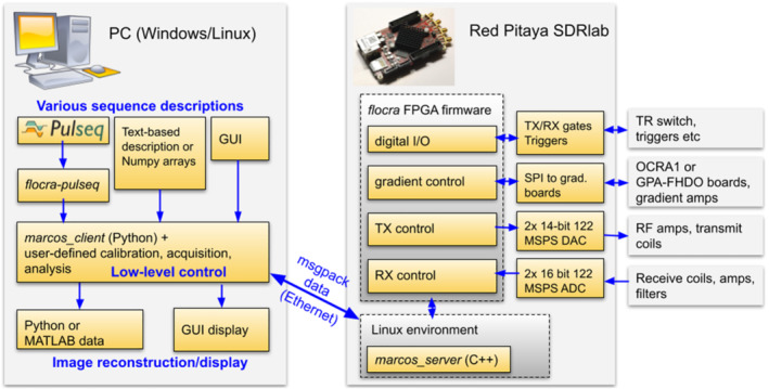
MaRCoS architecture, showing the main components in the software and hardware stacks
The cost of setting up a new MaRCoS control system amounts to less than 2,000 USD, including the Red Pitaya SDRlab ( USD), the components for the GPA‐FHDO or OCRA1 digital‐to‐analog converter (DAC) boards (<300 USD, including the power supply), a standard control computer (<1, 000 USD), and cables (<100 USD). All components can be purchased from vendors that operate globally. Here, we have excluded power electronics modules for amplification of RF and gradient pulses (the latter can be optionally installed on the GPA‐FHDO), and other RF circuitry (low‐noise amplifier, filters, Tx/Rx switch, etc.). The Open‐Source Imaging Initiative (OSI2 ONE, 42 ) has recently released designs for all these other parts, which can be built for less than 3,000 USD (component cost).
In terms of power requirements, a complete low‐field portable MRI system can consume less than 500 W at full power 16 ; it can be powered by a battery or a small fuel‐based generator, and the MaRCoS contribution to this figure is negligible.
2.2. LF‐MRI systems
2.2.1. MGH
The MaRCoS console was paired with a 0.36 T tabletop MRI scanner made using open‐source hardware components (Figure 2). The tabletop scanner has a 1 cm field of view (FOV) and was originally developed as an educational tool for university courses at Massachusetts Institute of Technology. Co‐planar shielded gradient coils driven by a low‐cost, low‐voltage gradient power amplifier (GPA‐FHDO) 40 are nested between two 6 in. diameter permanent magnets set up in a dipole configuration. The RF system consists of a small solenoid coil connected to a low‐cost Tx/Rx switch, preamplifier, and a 1 W RF power amplifier. The hardware suite was summarized by Cooley et al. 23 The setup was previously paired with a MEDUSA console 29 and later adapted for use with OCRA. With Red Pitaya‐based consoles, the total scanner cost is below 10k USD. Pulse sequences are written in the Pulseq MATLAB environment and then imported into the MaRCoS framework using custom interpreter software (see below).
FIGURE 2.
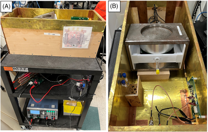
Fully open‐source tabletop MRI scanner for education and research at MGH. A, Complete setup including 0.36 T dipole magnet, GPA‐FHDO board, Red Pitaya‐based console, and home‐built RF hardware. B, Inner view with phantom inside the scanner
2.2.2. LUMC
The custom‐built 50 mT (2.15 MHz) Halbach‐based MRI scanner (Figure 3) is constructed using 2948 12 mm cuboid N48 neodymium iron boron magnets arranged in a cylindrical Halbach configuration. The magnet is 50.6 cm long and has a 27 cm diameter bore. The magnetic field homogeneity is optimized over a 20 cm diameter spherical volume (DSV) placed at the center of the magnet. A set of three linear gradient coils was constructed using a target field method, adapted for the transverse orientation intrinsic to cylindrical Halbach arrays. A custom‐built 1 kW RF amplifier with 56 dB gain is used to amplify the RF pulses. The gradient waveforms are amplified using a custom‐built three‐axis current‐controlled gradient amplifier, powered using two Delta Elektronika SM 18‐50 direct current power supplies (Zierikzee, The Netherlands). The entire setup is placed inside a Faraday cage constructed from aluminum extrusion and 2 mm thick aluminum plates. An RF shield is placed inside the inner surface of the bore. During in vivo experiments the body extends out of the Faraday and couples significant amounts of electromagnetic interference (EMI) into the RF coil. In order to reduce this EMI the body is placed under a conductive cloth (4711 series, Holland Shielding Systems, Dordrecht, The Netherlands). Further details on the system can be found in References 12 , 24 .
FIGURE 3.
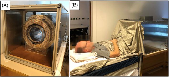
50 mT system at LUMC. A, Photograph of the scanner inside the Faraday cage. B, Photograph during an in vivo acquisition
2.2.3. i3M
The MaRCoS‐powered, portable system at i3M is shown in Figure 4 and described in Reference 16 . The scanner design is largely based on the LUMC system described above, with an extra layer of magnets to reach mT. The field homogeneity is shimmed from 15 700 to 3100 ppm (parts per million) over 20 cm DSV. This is achieved with approximately 1100 smaller permanent magnets placed in rings inside and concentric to the main magnet, following an optimized result obtained with a non‐linear integer minimization method. The diameter and length of the whole system are around 53 and 51 cm respectively, and it weighs approximately 200 kg. The gradient coils are wound on and glued to 12 3D‐printed Nylon molds, and the whole assembly is supported by a methacrylate cylinder. Gradient waveforms are generated with either an OCRA1 board 43 or the open‐source GPA‐FHDO board 40 connected to the Red Pitaya via a serial peripheral interface (SPI), and amplified by AE Techron 7224 power amplifiers (Elkhart, IN, USA). The single Tx/Rx RF antenna is a solenoid coil tuned and impedance matched to the proton Larmor frequency (3.076 MHz). The RF coil holder was printed in polylactic acid, and the wire was fixed with cyanoacrylate adhesive. The coil is inside a grounded Faraday cage for noise immunity and to prevent interference between the gradients and the RF system, and again a conductive cloth is used for in vivo imaging. The RF low‐noise and power amplifiers, as well as the Tx/Rx switch, were purchased from Barthel HF‐Technik (Aachen, Germany).
FIGURE 4.
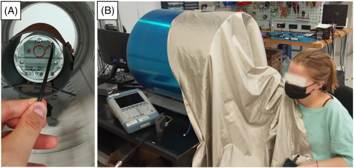
70 mT system at i3M. A, Photograph of the inside and a phantom used by the American College of Radiation for their MRI accreditation program. 44 B, Photograph of the outside and a volunteer during an in vivo acquisition
2.3. Pulse sequences and image reconstruction
To give an idea of the potential applications of MaRCoS we have demonstrated its functionality in the aforementioned MRI scanners. To this end, we show numerous images in Section 3 that benchmark the performance of MaRCoS in terms of programming flexibility and its capability to execute multiple pulse sequences and to reconstruct and process the acquired data. All sequence parameters are compiled in Table 1 for readability.
TABLE 1.
Image acquisition parameters
| Figure | Sample / Scanner | Sequence | FOV (mm3) | No of pixels | Bandwidth (kHz) | (ms) | (ms) | Other params | Avgs | Scan time (min) | ||
|---|---|---|---|---|---|---|---|---|---|---|---|---|
| 6A) | Phantom / i3M | 3D‐SE |
|
|
30 | 500 | 20 | 1 | 15 | |||
| 6B) | Phantom / i3M | 3D‐RARE |
|
|
30 | 500 | 20 | Center‐out ETL = 10 ESP = 20 ms | 1 | 1.5 | ||
| 6C) | Phantom / i3M | 3D‐STIR |
|
|
30 | 500 | 20 | = 20 ms | 4 | 60 | ||
| 6D) | Phantom / i3M | 3D‐GRE |
|
|
60 | 10 | 2 | Flip angle = | 1 | 9 | ||
| 6E) & F) | Phantom / i3M | 3D‐SE (radial) |
|
|
30 | 100 | 20 | Radial in Equispaced in Spokes per slice = 95 | 1 | 4.8 | ||
| 7 | Phantom / LUMC | 3D‐SE |
|
|
20 | 1000 | 30 | 1 | 33.3 | |||
| 8 | Phantom / MGH | 2D‐RARE |
|
|
30 | 5000 | 53 | Axial ETL = 32 ESP = 9.5 ms | 4 | 1 | ||
| 9A) & E) | Elbow / i3M | 3D‐RARE |
|
|
30 | 400 | 20 | Center‐out ETL = 10 ESP = 20 ms | 6 | 12 | ||
| 9B) & F) | Forearm / i3M | 3D‐RARE |
|
|
30 | 400 | 20 | Center‐out ETL = 10 ESP = 20 ms | 6 | 12 | ||
| 9C) & G) | Wrist / i3M | 3D‐RARE |
|
|
30 | 400 | 20 | Center‐out ETL = 10 ESP = 20 ms | 7 | 11.2 | ||
| 9D) & H) | Hand / i3M | 3D‐RARE |
|
|
30 | 400 | 20 | Center‐out ETL = 10 ESP = 20 ms | 13 | 10.4 | ||
| 10A) & D) | Ankle / i3M | 3D‐RARE |
|
|
20 | 100 | 20 | Center‐out ETL = 3 ESP = 20 ms | 36 | 18 | ||
| 10B) & E) | Ankle / i3M | 3D‐RARE |
|
|
20 | 1000 | 40 | Out‐out ETL = 3 ESP = 40 ms | 2 | 9 | ||
| 10C) & F) | Ankle / i3M | 3D‐RARE |
|
|
20 | 1000 | 20 | Center‐out ETL = 5 ESP = 20 ms | 3 | 14 |
Note: in RARE sequences corresponds to the effective echo time.
In terms of pulse sequences, in Section 3 we show images of phantoms taken with SE, RARE, STIR, GRE and radial (non‐Cartesian) acquisitions. Figure 5 shows an example of sequence programming (3D‐RARE) with the MaRCoS GUI and a graphical representation of the programmed sequence in the integrated viewer. Furthermore, we have demonstrated low‐field images with different contrast mechanisms ( , and ) and tested two image reconstruction modules programmed in Python and integrated into the GUI: a standard Fourier transform based method, and non‐uniform fast Fourier transform (NUFFT), which can be used for non‐Cartesian reconstruction. 45
FIGURE 5.
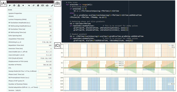
Programming and execution of a 3D‐RARE pulse sequence in MaRCoS: A, GUI window for definition of sequence parameters and execution; B, snippet of Python code; C, MaRCoS viewer
3. RESULTS AND DISCUSSION
3.1. Phantom images
In the following sections we present phantom images acquired in the different setups: the i3M images have been taken with a variety of pulse sequences, the LUMC images show multi‐Rx capabilities as required for parallel imaging, and the MGH section demonstrates the compatibility between MaRCoS and Pulseq.
3.1.1. i3M
First we show the performance of MaRCoS with five 3D pulse sequences and two reconstruction algorithms. To this end, we use a structured phantom employed in the MRI accreditation program of the American College of Radiology. 44 The images in Figure 6 are all raw reconstructions, without filtering or post‐processing. All pulse sequence parameters are included in Table 1. SE and GRE sequences (Figure 6A and 6D respectively) are the simpler ones and serve as references to evaluate the reconstruction quality of the rest. SE performs slightly better than GRE, since the former is less sensitive to magnetic field inhomogeneities. The RARE acquisition (Figure 6B) is run with an echo train length (ETL) of ten ‐pulses. This shortens the scan time from 15 min (Figure 6A) to 90 s, but the image is slightly blurred due to decay and small variable delays in the echo formation caused by a small tuning mismatch between the gradient amplifiers and coils. The STIR sequence (Figure 6C) is executed with an inversion time ( ) of 45 ms, previously calibrated to null the contribution from the smaller cylinder on the right in the phantom, which contains a substance with characteristic times and different from those of the rest of the sample. The difference in values is small, however, so this sequence retrieves significantly less signal per unit time than the rest. For the signal‐to‐noise ratio (SNR) in the image, the total scan time took around an hour. Finally, the images in Figure 6E and 6F show reconstructions after a radial ‐space acquisition. Both are reconstructed from the exact same data, one with a standard fast Fourier transform (FFT) after regridding with triangulation‐based linear interpolation, the other with an NUFFT, where ‐space points are weighted by density. 45 The latter performs notably better in terms of border definition, but the reconstruction is overall noisier and contains a circular artifact towards the outer region of the FOV. Both images are slightly blurry as a consequence of an imperfect ‐space trajectory due to the tuning mismatch between the gradient amplifiers and the gradient coils. All in all, different sequences perform significantly different and can be advantageous for different applications. We find 3D‐RARE most reliable in a large variety of situations, and have chosen it for the in vivo acquisitions below.
FIGURE 6.
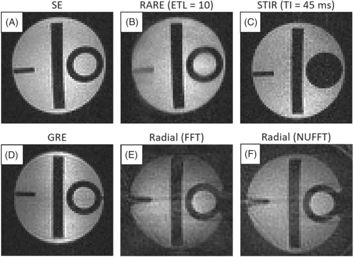
Images of a certified phantom, 44 acquired with different pulse sequences at i3M
In order to further understand the system capabilities, we also ran a phase stability experiment with a Carr–Purcell–Meiboom–Gill (CPMG) pulse sequence. 46 , 47 The sequence consisted of 100 repetitions of an echo train with 50 echoes, with 10 ms echo spacing (ESP) and 1 s repetition time. The phase of the acquired echoes was stable down to 180 mrad (standard deviation) for all echoes in the train, and down to approximately 60 mrad for 20%. This implies that the phase and magnitude of control pulses, as well as their timing, are all sufficiently stable for demanding MRI applications. Other relevant measurements on the performance of MaRCoS can be found in Reference 1 .
3.1.2. LUMC
In this experiment we evaluate the multi‐Rx capabilities of MaRCoS. To this end we built a dual antenna comprising a saddle coil (188 mm diameter, 202 mm long) for both Tx and Rx, and a solenoid (156 mm diameter, 150 mm long) for Rx only (Figure 7D). Coupling between the coils is inherently suppressed due to their orthogonal orientations ( dB). The phantom (120 mm diameter, 144 mm long) images in Figure 7 were acquired with a 3D‐SE sequence (Table 1). The top row shows images where the data from the individual channels were filtered with a scaled sine‐bell‐squared filter prior to reconstruction with FFT. The middle row corresponds to a direct combination of the raw data. To combine the images, the data of each channel were normalized to their respective noise measurement prior to summing the magnitude images from the individual channels. The brightness of the single‐Rx images was scaled from zero to the maximum value of each of the channels.
FIGURE 7.
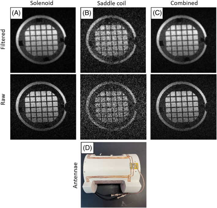
Images of a structured phantom acquired with simultaneous reception from two Rx coils at LUMC. A, Reconstruction using the data from the solenoid coil. B, Reconstruction using the data from the saddle coil. C, Reconstruction using the combined data from both coils. D, Photograph of the double‐coil antenna, with the solenoid inside and the saddle coil outside
3.1.3. MGH
A Python interpreter was created to interface between the open‐source Pulseq sequence programming environment and MaRCoS. 41 Previous Pulseq interpreters were used with commercial high‐field MRI scanners; our work is the first extension to an open‐source console. Pulseq uses simple syntax in MATLAB 39 or Python 48 to generate a .seq text file that specifies all gradient, RF, and readout events occurring during a pulse sequence. This enables students and MRI physicists to rapidly code up sequences in the user‐friendly Pulseq programming language. The .seq file is converted to console‐specific executable code using the interpreter software. The Pulseq–MaRCoS interpreter software is available on GitHub. 49 Figure 8 shows image data acquired using the Pulseq–MaRCoS framework with a 2D‐RARE spin‐echo‐train pulse sequence. The axial projection of the star‐shaped phantom (10 mm in diameter) is reconstructed from the acquired ‐space data with FFT. The signal arising in the background of the sample originates from water in the pores of the 3D‐printed cylinder with a star‐shaped cavity at the center, since this material is not 100% solid. The shading of the image on the left‐hand side is most likely due to the relatively poor field homogeneity (even with linear shims applied) and the limited bandwidth of the RF pulse.
FIGURE 8.
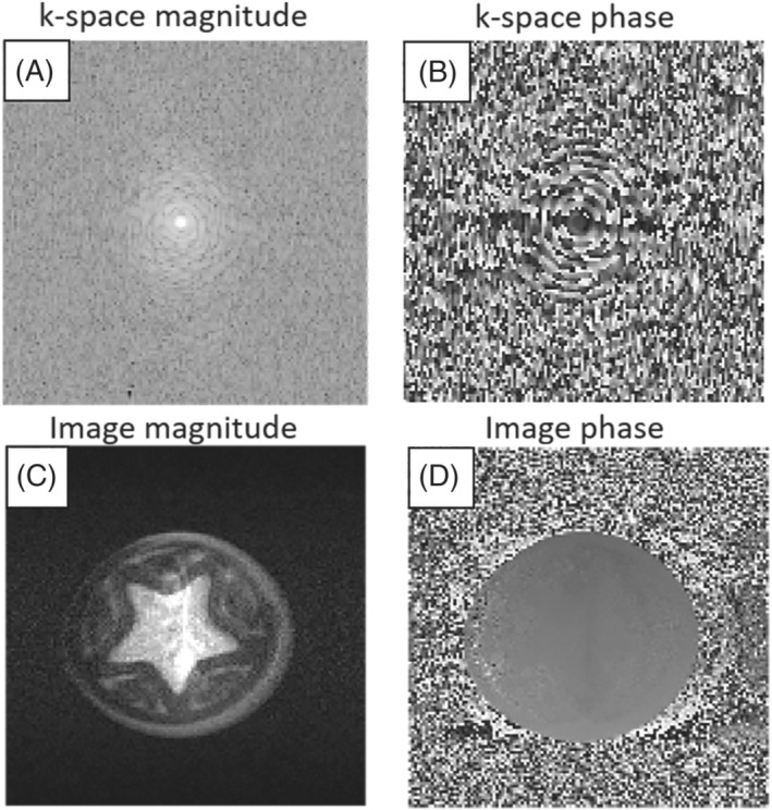
Image data of a star‐shaped phantom acquired at MGH with a RARE spin‐echo‐train pulse sequence diagram generated by the open‐source Pulseq sequence‐programming environment in MATLAB. All excitation and refocusing RF pulses are 80 s long following CPMG phase. A, ‐space magnitude. B, ‐space phase. C, Image magnitude. D, Image phase
3.2. In vivo performance
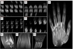
The i3M in vivo acquisitions in Figure 9 show images of the right upper limb of a healthy volunteer. These correspond to four independent scans of the hand, wrist, forearm, and elbow. They are all ‐weighted 3D‐RARE acquisitions (see Table 1) and have been taken in less than 12 min each. The SNR, contrast, and spatial resolution suffice to identify different tissues in the anatomy, including muscle, fat, tendons, bone, and bone marrow.
FIGURE 9.
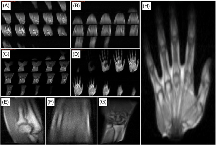
In vivo images of the right upper limb taken at i3M with 3D‐RARE sequences and reconstructed with FFT. A–D, All slices for the elbow, forearm, wrist, and hand, respectively. E–H, Magnified views of slices selected from A–D
To demonstrate different tissue contrasts, we acquired images from the right ankle of another volunteer. The images in the top row of Figure 10 correspond to ‐ and ‐weighted acquisitions. The bottom row shows the result of applying a block‐matching and four‐dimensional (BM4D) filter 50 to the above images. All pulse sequence parameters are provided in Table 1.
FIGURE 10.
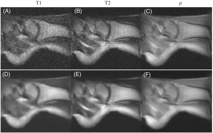
In vivo images of the right ankle of a healthy volunteer taken at i3M with 3D‐RARE sequences and reconstructed with FFT. A–C, A selected slice for the and ‐weighted acquisitions respectively. D–F, The same as A–C but BM4D filtered
4. CONCLUSION AND OUTLOOK
With this work we have demonstrated some of the main capabilities of low‐field systems equipped with the first stable release of MaRCoS, including pulse sequences for in vivo extremity imaging in clinically viable times and with sufficient quality for initial screening for common pathologies. Our results show that this platform is capable of driving many different system configurations, which has been possible thanks to collaboration and a commitment to detailed documentation. The different sequence programming capabilities, from the self‐developed GUI to more widespread “overlays” such as Pulseq, greatly facilitates the development of pulse sequences to users with different demands and expertise. MaRCoS is in continuous evolution by virtue of an open, active, international network of collaborators, and we have planned a sizable upgrade for the coming months. This will include new pulse sequences, such as steady‐state free precession, 4 zero echo time, 51 and spiral 52 ; data oversampling capabilities and advanced image reconstruction methods 53 ; daisy‐chaining of multiple Red Pitaya units for multi‐Rx MRI beyond what we show in this work, as required for parallel imaging and acceleration techniques 54 ; real‐time decision‐making capabilities during sequence execution, for potential optimization of pulses/gradients/delays via feedback control during data acquisition; and integration with post‐processing and deep learning modules for sequence optimization, image reconstruction, denoising, or segmentation tasks. 55 The MaRCoS GUI will also continue to be developed to facilitate operation by users with different degrees of expertise, and to become readily usable in clinical environments by standardizing data formats and structure and complying with clinical procedural requirements. The MaRCoS community has the commitment to keep this project open source and welcomes the participation of new users and contributors.
CONFLICT OF INTEREST
TG‐N is a researcher at Tesoro Imaging S.L. JMA, FG and JA are co‐founders of PhysioMRI Tech S.L. JPS is a consultant for Neuro42, Inc. All other authors declare no competing interests.
ETHICAL STATEMENT
In vivo experiments were carried out following Spanish regulations and under the research agreement from La Fe Hospital in Valencia (IIS‐F‐PG‐22‐02, agreement number 2019‐139‐1). Informed consents to participate and for publication were obtained from the volunteers prior to study commencement.
CONTRIBUTIONS
TG‐N and JMA acquired data on the i3M scanner. RP‐G, TG‐N, JMA, FG and JA conceived and built the i3M scanner. TO'R acquired data on the LUMC scanner. TO'R and AW conceived and built the LUMC scanner. LC‐B wrote the Python interpreter to convert Pulseq files to MaRCoS/flocra format. JPS wrote Pulseq sequence code and acquired data on the MGH scanner. VN and BM developed MaRCoS. YVG and JMA developed the MaRCoS GUI. JA, AW and JPS wrote the paper, with input from all authors.
CODE AVAILABILITY
MaRCoS, the GUI, and the Pulseq interface are publicly available from open‐source repositories at https://github.com/vnegnev/marcos_server, https://github.com/yvives/PhysioMRI_GUI, and https://github.com/stockmann-lab/mgh_marcos, respectively.
ACKNOWLEDGMENT
We thank Thomas Witzel and Marcus Prier for discussions. This work was supported by the Ministerio de Ciencia e Innovación of Spain through research grant PID2019‐111436RB‐C21. Action co‐financed by the European Union through the Programa Operativo del Fondo Europeo de Desarrollo Regional (FEDER) of the Comunitat Valenciana (IDIFEDER/2018/022 and IDIFEDER/2021/004).
Guallart‐Naval T, O'Reilly T, Algarín JM, et al. Benchmarking the performance of a low‐cost magnetic resonance control system at multiple sites in the open MaRCoS community. NMR in Biomedicine. 2023;36(1):e4825. doi: 10.1002/nbm.4825
Funding information European Regional Development Fund; Ministerio de Ciencia e Innovación
DATA AVAILABILITY STATEMENT
The data that support the findings of this study are available from the corresponding author upon reasonable request.
REFERENCES
- 1. Negnevitsky V, Vives‐Gilabert Y, Algarín JM. MaRCoS, an open‐source electronic control system for low‐field MRI. arXiv preprint arXiv:2208.01616; 2022. [DOI] [PubMed]
- 2. Negnevitsky V, O'Reilly T, Pellicer‐Guridi R. MaRCoS: a high‐performance open‐source control system for affordable MRI. Book of Abstracts ESMRMB 2021 38th Annual Scientific Meeting, Vol. 34: Springer; 2021:172. [Online]. Available: doi: 10.1007/s10334-021-00947-8 [DOI] [Google Scholar]
- 3. Craven‐Brightman L, O'Reilly T, Menküc B. Research and educational applications of an open source, low cost MRI console with an accessible pulse sequence programming environment. In: Proceedings of the 2021 ISMRM & SMRT Annual Meeting and Exhibition. ISMRM; 2021:748. [Online]. Available: https://cds.ismrm.org/protected/21MPresentations/abstracts/0748.html [Google Scholar]
- 4. Sarracanie M, LaPierre CD, Salameh N, Waddington DEJ, Witzel T, Rosen MS. Low‐cost high‐performance MRI. Sci Rep. 2015;5(1):15177. [Online]. Available: https://www.nature.com/articles/srep15177 [DOI] [PMC free article] [PubMed] [Google Scholar]
- 5. Marques JP, Simonis FF, Webb AG. Low‐field MRI: an MR physics perspective. J Magn Reson Imaging. 2019;49(6):1528‐1542. [Online]. Available: doi: 10.1002/jmri.26637 [DOI] [PMC free article] [PubMed] [Google Scholar]
- 6. Sarracanie M, Salameh N. Low‐field MRI: how low can we go? A fresh view on an old debate. Front Phys. 2020;8:172. [Online]. Available: doi: 10.3389/fphy.2020.00172/full [DOI] [Google Scholar]
- 7. Wald LL, McDaniel PC, Witzel T, Stockmann JP, Cooley CZ. Low‐cost and portable MRI. J Magn Reson Imaging. 2020;52(3):686‐696. [Online]. Available: doi: 10.1002/jmri.26942 [DOI] [PMC free article] [PubMed] [Google Scholar]
- 8. Bhat SS, Fernandes TT, Poojar P, da Silva Ferreira M, Rao PC, Hanumantharaju MC, Ogbole G, Nunes RG, Geethanath S. Low‐field MRI of stroke: challenges and opportunities. J Magn Reson Imaging. 2021;54(2):372‐390. [Online]. Available: doi: 10.1002/jmri.27324 [DOI] [PubMed] [Google Scholar]
- 9. McDaniel PC, Cooley CZ, Stockmann JP, Wald LL. The MR cap: a single‐sided MRI system designed for potential point‐of‐care limited field‐of‐view brain imaging. Magn Reson Med. 2019;82(5):1946‐1960. [Online]. Available: doi: 10.1002/mrm.27861 [DOI] [PMC free article] [PubMed] [Google Scholar]
- 10. Nakagomi M, Kajiwara M, Matsuzaki J, Tanabe K, Hoshiai S, Okamoto Y, Terada Y. Development of a small car‐mounted magnetic resonance imaging system for human elbows using a 0.2 T permanent magnet. J Magn Reson. 2019;304:1‐6. [DOI] [PubMed] [Google Scholar]
- 11. Cooley CZ, McDaniel PC, Stockmann JP. A portable scanner for magnetic resonance imaging of the brain. Nature Biomed Eng. 2020;5(3):229‐239. [Online]. Available: https://www.nature.com/articles/s41551-020-00641-5 [DOI] [PMC free article] [PubMed] [Google Scholar]
- 12. O'Reilly T, Teeuwisse WM, Gans D, Koolstra K, Webb AG. In vivo 3D brain and extremity MRI at 50 mT using a permanent magnet Halbach array. Magn Reson Med. 2020;85:495‐505. [Online]. Available: doi: 10.1002/mrm.28396 [DOI] [PMC free article] [PubMed] [Google Scholar]
- 13. Sheth KN, Mazurek MH, Yuen MM. Assessment of brain injury using portable, low‐field magnetic resonance imaging at the bedside of critically ill patients. JAMA Neurol. 2021;78(1):41‐47. [Online]. Available: https://jamanetwork.com/journals/jamaneurology/fullarticle/2769858 [DOI] [PMC free article] [PubMed] [Google Scholar]
- 14. Mazurek MH, Yuen MM, Cahn BA. Low‐field, portable magnetic resonance imaging at the bedside to assess brain injury in patients with severe COVID‐19. Neurology. 2021;96:1349. Supplement 15. [Google Scholar]
- 15. Liu Y, Leong ATL, Zhao Y. A low‐cost and shielding‐free ultra‐low‐field brain MRI scanner. Nat Commun. 2021;12:7238. [Online]. Available: https://www.nature.com/articles/s41467-021-27317-1 [DOI] [PMC free article] [PubMed] [Google Scholar]
- 16. Guallart‐Naval T, Algarín J, Pellicer‐Guridi R. Portable magnetic resonance imaging of patients indoors, outdoors and at home. Sci Rep. 2022;12:13147. [Online]. Available: https://www.nature.com/articles/s41598-022-17472-w [DOI] [PMC free article] [PubMed] [Google Scholar]
- 17. O'Reilly T, Webb AG. In vivo and relaxation time maps of brain tissue, skeletal muscle, and lipid measured in healthy volunteers at 50 mT. Magn Reson Med. 2021;87(2):884‐895. [Online]. Available: doi: 10.1002/mrm.29009 [DOI] [PMC free article] [PubMed] [Google Scholar]
- 18. Sarracanie M. Fast quantitative low‐field magnetic resonance imaging with OPTIMUM—optimized magnetic resonance fingerprinting using a stationary steady‐state Cartesian approach and accelerated acquisition schedules. [Online]. Available: https://journals.lww.com/investigativeradiology/Fulltext/9000/Fast_Quantitative_Low_Field_Magnetic_Resonance.98659.aspx; 2021. [DOI] [PMC free article] [PubMed]
- 19. Algarín JM, Díaz‐Caballero E, Borreguero J. Simultaneous imaging of hard and soft biological tissues in a low‐field dental MRI scanner. Sci Rep. 2020;10(1):21470. [Online]. Available: doi: 10.1038/s41598-020-78456-2 [DOI] [PMC free article] [PubMed] [Google Scholar]
- 20. González JM, Borreguero J, Pallá s E. Prepolarized MRI of hard tissues and solid‐state matter. arXiv preprint arXiv:2110.03417; 2021. [DOI] [PMC free article] [PubMed]
- 21. Borreguero J, Galve F, Algari˙n JM, Benlloch JM, Alonso J. Slice‐selective zero echo time imaging of ultra‐short tissues based on spin‐locking. arXiv preprint arXiv:2201.06305; 2022.
- 22. Van Speybroeck CD, O'Reilly T, Teeuwisse W, Arnold PM, Webb AG. Characterization of displacement forces and image artifacts in the presence of passive medical implants in low‐field (<100 mT) permanent magnet‐based MRI systems, and comparisons with clinical MRI systems. Phys Med. 2021;84:116‐124. [Online]. Available: https://pubmed.ncbi.nlm.nih.gov/33894581/ [DOI] [PubMed] [Google Scholar]
- 23. Cooley CZ, Stockmann JP, Witzel T. Design and implementation of a low‐cost, tabletop MRI scanner for education and research prototyping. J Magn Reson. 2020;310:106625. [DOI] [PubMed] [Google Scholar]
- 24. O'Reilly T, Teeuwisse W, Webb A. Three‐dimensional MRI in a homogenous 27 cm diameter bore Halbach array magnet. J Magn Reson. 2019;307:106578. [Online]. Available: https://linkinghub.elsevier.com/retrieve/pii/S1090780719302174 [DOI] [PubMed] [Google Scholar]
- 25. De Vos B, Fuchs P, O'Reilly T, Webb A, Remis R. Gradient coil design and realization for a Halbach‐based MRI system. IEEE Trans Magn. 2020;56:3. [Google Scholar]
- 26. Wenzel K, Alhamwey H, O'Reilly T, Riemann LT, Silemek B, Winter L. ‐shimming methodology for affordable and compact low‐field magnetic resonance imaging magnets. Front Phys. 2021;9:704566. [Google Scholar]
- 27. Koonjoo N, Zhu B, Bagnall GC, Bhutto D, Rosen MS. Boosting the signal‐to‐noise of low‐field MRI with deep learning image reconstruction. Sci Rep. 2021;11:8248. [Online]. Available: https://www.nature.com/articles/s41598-021-87482-7 [DOI] [PMC free article] [PubMed] [Google Scholar]
- 28. Arnold TC, Baldassano SN, Litt B, Stein JM. Simulated diagnostic performance of low‐field MRI: harnessing open‐access datasets to evaluate novel devices. Magn Reson Imaging. 2022;87:67‐76. [Online]. Available: https://linkinghub.elsevier.com/retrieve/pii/S0730725X21002575 [DOI] [PMC free article] [PubMed] [Google Scholar]
- 29. Stang PP, Conolly SM, Santos JM, Pauly JM, Scott GC. Medusa: a scalable MR console using USB. IEEE Trans Med Imaging. 2012;31(2):370‐379. [DOI] [PMC free article] [PubMed] [Google Scholar]
- 30. Tang W, Wang W, Liu W, Ma Y, Tang X, Xiao L, Gao JH. A home‐built digital optical MRI console using high‐speed serial links. Magn Reson Med. 2015;74(2):578‐588. [Online]. Available: doi: 10.1002/mrm.25403 [DOI] [PubMed] [Google Scholar]
- 31. Hasselwander CJ, Cao Z, Grissom WA. gr‐MRI: a software package for magnetic resonance imaging using software defined radios. J Magn Reson. 2016;270:47‐55. [DOI] [PMC free article] [PubMed] [Google Scholar]
- 32. Anand S, Stockmann JP, Wald LL, Witzel T. A low‐cost (<$500 USD) FPGA‐based console capable of real‐time control. In: Proceedings of the 2018 ISMRM & SMRT Annual Meeting and Exhibition in Paris. ISMRM; 2018:948. [Google Scholar]
- 33. OCRA MRI . [Online]. Available: https://openmri.github.io/ocra/
- 34. Takeda K. Chapter 7—Highly customized NMR systems using an open‐resource home‐built spectrometer. In: Webb GA, ed. Annual Reports on NMR Spectroscopy: Academic; 2011:355‐393. [Online]. Available: https://www.sciencedirect.com/science/article/pii/B9780080970721000078 [Google Scholar]
- 35. Michal CA. A low‐cost multi‐channel software‐defined radio‐based NMR spectrometer and ultra‐affordable digital pulse programmer. Concepts Magn Reson B. 2018;48B(3):e21401. [Online]. Available: doi: 10.1002/cmr.b.21401 [DOI] [Google Scholar]
- 36. Ang A, Bourne M, Obruchkov S, Dykstra R. Construction of a PXIe platform for instrumentation development. In: 11th International Conference on Sensing Technology (ICST) 2017. IEEE; 2017:1‐4. [Google Scholar]
- 37. MaRCoS GitHub . [Online]. Available: https://github.com/vnegnev/marcos_extras/wiki
- 38. MaRCoS GUI GitHub . [Online]. Available: https://github.com/yvives/PhysioMRI_GUI
- 39. Pulseq GitHub . [Online]. Available: https://github.com/pulseq/pulseq
- 40. GPA‐FHDO . [Online]. Available: https://github.com/menkueclab
- 41. Layton KJ, Kroboth S, Jia F. Pulseq: a rapid and hardware‐independent pulse sequence prototyping framework. Magn Reson Med. 2017;77(4):1544‐1552. [Online]. Available: doi: 10.1002/mrm.26235 [DOI] [PubMed] [Google Scholar]
- 42. OSI2 ONE . [Online]. Available: https://gitlab.com/osii-one
- 43. OCRA1—SPI controlled 4 channel 18 BIT DAC and RF attenuator . [Online]. Available: https://zeugmatographix.org/ocra/2020/11/27/ocra1-spi-controlled-4-channel-18bit-dac-and-rf-attenutator/
- 44. Sipilä O, Mäkelä T. Repeated quality control measurements with the small ACR MRI phantom. European Congress of Radiology—ECR; 2013.
- 45. Greengard L, Lee J‐Y. Accelerating the nonuniform fast Fourier transform. SIAM Rev. 2004;46(3):443‐454. [Online]. Available: doi: 10.1137/S003614450343200X [DOI] [Google Scholar]
- 46. Carr HY. Steady‐state free precession in nuclear magnetic resonance. Phys Rev. 1958;112(5):1693‐1701. [Google Scholar]
- 47. Meiboom S, Gill D. Modified spin‐echo method for measuring nuclear relaxation times. Rev Sci Instrum. 1958;29(8):688‐691. [Google Scholar]
- 48. PyPulseq Git Repository . [Online]. Available: https://github.com/imr-framework/pypulseq
- 49. MGH_MARCOS Project . [Online]. Available: https://github.com/stockmann-lab/mgh_marcos
- 50. Maggioni M, Katkovnik V, Egiazarian K, Foi A. Nonlocal transform‐domain filter for volumetric data denoising and reconstruction. IEEE Trans Image Process. 2013;22(1):119‐133. [DOI] [PubMed] [Google Scholar]
- 51. Grodzki DM, Jakob PM, Heismann B. Ultrashort echo time imaging using pointwise encoding time reduction with radial acquisition (PETRA). Magn Reson Med. 2012;67(2):510‐518. [DOI] [PubMed] [Google Scholar]
- 52. Campbell‐Washburn AE, Ramasawmy R, Restivo MC. Opportunities in interventional and diagnostic imaging by using high‐performance low‐field‐strength MRI. Radiology. 2019;293(2):384‐393. [DOI] [PMC free article] [PubMed] [Google Scholar]
- 53. Galve F, Alonso J, Algarí n JM, Benlloch JM. Model‐driven reconstruction with phase‐constrained highly‐oversampled MRI. arXiv preprint arXiv:2007.15674; 2020.
- 54. Pruessmann KP, Weiger M, Scheidegger MB, Boesiger P. SENSE: sensitivity encoding for fast MRI. Magn Reson Med. 1999;42(5):952‐962. [PubMed] [Google Scholar]
- 55. Lundervold AS, Lundervold A. An overview of deep learning in medical imaging focusing on MRI. Z Med Phys. 2019;29(2):102‐127. Special Issue: Deep Learning in Medical Physics. [Online]. Available: https://www.sciencedirect.com/science/article/pii/S0939388918301181 [DOI] [PubMed] [Google Scholar]
Associated Data
This section collects any data citations, data availability statements, or supplementary materials included in this article.
Data Availability Statement
The data that support the findings of this study are available from the corresponding author upon reasonable request.


