Abstract
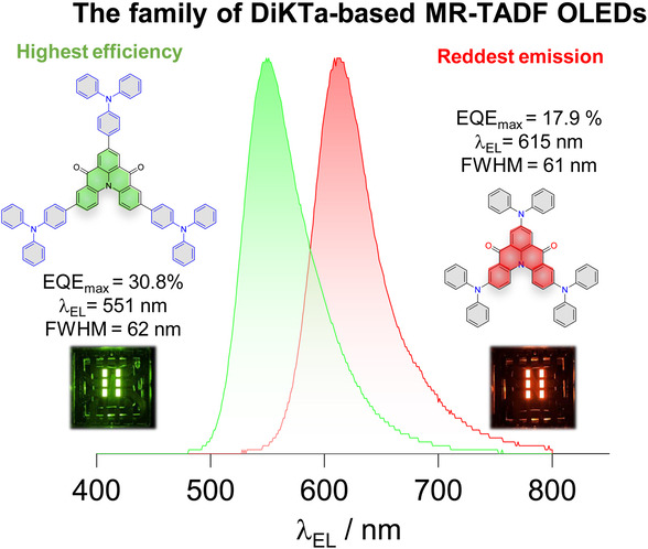
Herein, we demonstrate how judicious selection of the donor decorating a central multi‐resonant thermally activated delayed fluorescence (MR‐TADF) core based on DiKTa can lead to very high‐performance OLEDs. By decorating the DiKTa core with triphenylamine (TPA) and diphenylamine (DPA), 3TPA‐DiKTa and 3DPA‐DiKTa exhibit bright, narrowband green and red emission in doped films, respectively. The OLEDs based on these emitters showed record‐high performance for this family of emitters with maximum external quantum efficiencies (EQEmax) of 30.8 % for 3TPA‐DiKTa at λEL of 551 nm and 16.7 % for 3DPA‐DiKTa at λEL=613 nm. The efficiency roll‐off in the OLEDs was improved significantly by using 4CzIPN as an assistant dopant in hyperfluorescence (HF) devices. The outstanding device performance has been attributed to preferential horizontal orientation of the transition dipole moments of 3TPA‐DiKTa and 3DPA‐DiKTa.
Keywords: Horizontal Orientation, Hyperfluorescence, Multi-Resonance, Organic Light-Emitting Diodes, Thermally Activated Delayed Fluorescence
Through careful selection of donor substituents about the DiKTa core, record‐high efficiency green‐emitting OLEDs were fabricated, with EQEmax of 30.8 %, and the reddest MR‐TADF OLEDs have been reported based on ketone‐containing multi‐resonant thermally activated delayed fluorescent emitters.
Introduction
Organic light‐emitting diodes (OLEDs) have emerged as an exciting display technology that has steadily gained market share in a number of consumer electronic markets, from mobile phones and smart watches to televisions and monitors. The quality of an OLED depends on three key factors: its stability, its efficiency and its color purity. All of these parameters are linked in part to the intrinsic properties of the emitter. Two strategies to achieve high color purity in the device are to (1) employ a narrowband emissive material and/or (2) employ color filters to select out the desired emission. The use of color filters leads inevitably to light being lost by absorption, and a lower efficiency device, [1] thus there is a strong desire to develop narrowband emitters. A high‐efficiency device also requires the use of emitter materials that can efficiently convert both singlet and triplet excitons into light. Two classes of emitters are capable of realizing 100 % internal quantum efficiency (IQE) in the device, these are phosphorescent compounds and compounds that emit via thermally activated delayed fluorescence (TADF). Organic TADF emitters harvest both singlet and triplet excitons via an endothermic reverse intersystem crossing (RISC) process that converts non‐emissive triplet excitons into singlets prior to light generation. [2] RISC is enabled when the energy gap between the lowest‐lying singlet and triplet excited states (ΔE ST) is sufficiently small. [3] A molecular design that shows a small exchange integral between molecular orbitals related to the excited state is responsible for the small ΔE ST in the emitter. This is typically accomplished using a twisted structure containing donor (D) and acceptor (A) fragments. [3d] However, the charge‐transfer (CT) excited state[ 2b , 4 ] and the large reorganization energy in the excited state lead to broad emission, characterized by large full width half‐maximum (FWHM) >80 nm.[ 3c , 5 ] The corresponding TADF OLEDs do not show the desired high color purity.
A solution is to use multi‐resonant TADF (MR‐TADF) emitters. [6] MR‐TADF emitters are typically based on p‐ and n‐doped nanographenes and so possess a rigid molecular structure. [7] The ingenious molecular design places each of the frontier molecular orbital (FMOs) on adjacent atoms thus leading to short‐range charge transfer (SRCT) between adjacent atoms, inducing the small ΔE ST to turn on TADF. The SRCT excited state that results from the transition from the HOMO to the LUMO coupled with the small reorganization energy result in narrowband emitters. Since the first examples of this class of emitter, documented in 2016 by Hatakeyama and co‐workers, more than 200 distinct examples have been reported, most of which show blue and green emission. [3a] We previously demonstrated that decorating a MR‐TADF core with peripheral donor groups can result in emission tuning. [8] However, when too strong donors are employed then the lowest energy excited states are no longer SRCT and the narrowband emission is lost. Rather, the emissive excited state becomes long‐range CT (LRCT) that is typically observed in donor‐acceptor TADF compounds. The aforementioned reports evidence of emission tuning from 462 to 608 nm using a peripheral decoration strategy on the MR‐TADF core; nevertheless, examples of red‐emitting MR‐TADF emitters remain rare.
Fluorobenzene, [9] tert‐butylcarbazole, [10] tert‐butylbenzene, [10a] and cyanobenzene [11] are the most frequently used substituents to decorate MR‐TADF emitters. These examples are either weak electron‐withdrawing and/or electron‐donating groups and so their incorporation does not disrupt the MR‐TADF character. Diphenylamine (DPA) possesses an intermediate electron‐donating ability between carbazole, which allows retention of MR‐TADF when it is added to a core, and dimethylacridan DMAC, which results in a D‐A emitter when it is decorated about a MR‐TADF core. The incorporation of peripheral DPA groups has been shown to red‐shift the emission of MR‐TADF compounds by Yasuda and co‐workers. For instance, DACz‐B (Figure 1) shows bright yellow narrowband emission [12] (photoluminescence emission peak wavelength, λPL=576 nm; full width half‐maximum (FWHM)=44 nm; photoluminescence quantum efficiencies (ΦPL) of 87 %), which is red‐shifted compared to Cz‐B (λPL=484 nm; FWHM=30 nm; ΦPL of 97 %, Figure S3) in 1 wt %‐doped 3,3′‐Di(9H‐carbazol‐9‐yl)‐1,1′‐biphenyl (mCBP) film. The OLED with DACz‐B produces yellow electroluminescence (peak electroluminescence wavelength, λEL=571 nm) with a maximum external EL quantum efficiency (EQEmax) of 19.6 %. Using a similar room temperature phosphorescence skeleton, TOAT, Adachi and co‐workers introduced different numbers of DPA groups para to the central nitrogen atom of the TOAT core (3, 4 and 5, see Figure S3). [13] This led to the realization of red emission with a FWHM 45 nm in toluene for emitter 5. Using the same TOAT core, Zhang and co‐workers reported DPA analogues mBDPA‐TOAT and pBDPA‐TOAT [14] that contained tert‐butyl groups on the periphery of the DPA groups (Figure 1), which showed orange emission of 571 (FWHM=34 nm) and 563 nm (FWHM=48 nm) in toluene, respectively. However, the OLEDs using a TOAT derivative typically show low device performance with EQEmax<18 %. We recently reported a study wherein the MR‐TADF OLEDs using 3Cz‐DiKTa as the emitter showed a λEL of 547 nm (FWHM=54 nm) and an EQEmax of 24.4 % (Figure S3 and Table S9). [8] This initial study revealed the fine balance that must be achieved when decorating MR‐TADF emitters with peripheral donors.
Figure 1.
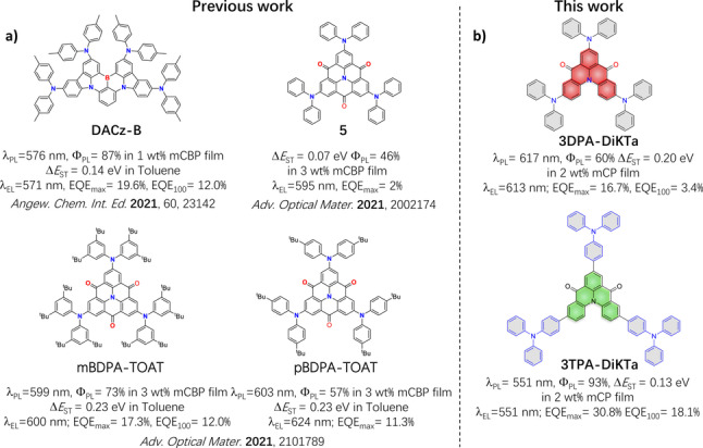
a) Chemical structures, photophysical and OLED data of reported MR‐TADF materials containing DPA units. b) Chemical structures, photophysical and OLED data of 3DPA‐DiKTa and 3TPA‐DiKTa of this work.
Here we report two emitters containing either three diphenylamine (DPA) or triphenylamine (TPA) donor groups decorating a central MR‐TADF core, DiKTa: 3DPA‐DiKTa and 3TPA‐DiKTa (Figure 1). Both emitters show a desired red‐shifted emission compared with 3Cz‐DiKTa [8] and behave as MR‐TADF compounds, characterized by small ΔE ST, narrow FWHM, and high ΦPL in 1,3‐bis(N‐carbazolyl)benzene (mCP) doped films. 3TPA‐DiKTa shows an emission maximum at λPL=551 nm (FWHM=58 nm) with ΦPL=93 % while the emission of 3DPA‐DiKTa is red‐shifted (λPL=617 nm, FWHM=56 nm, ΦPL=60 %) in the 2 wt % mCP doped films. Benefitting from both the high ΦPL and the enhanced light‐outcoupling associated with a preferential horizontal orientation of its transition dipole moment, the OLED with TPA‐DiKTa exhibits an EQEmax=30.8 % at a λEL of 551 nm (FWHM of 62 nm) and the device with 3DPA‐DiKTa shows an EQEmax of 16.7 % with a λEL of 615 nm (FWHM of 60 nm). The efficiency roll‐off was significantly improved from 41 % to 8.6 % for the OLED with 3TPA‐DiKTa and from 80 % to 51 % for the OLED with 3DPA‐DiKTa at 100 cd m−2 by using 1,2,3,5‐tetrakis(carbazol‐9‐yl)‐4,6‐dicyanobenzene, 2,4,5,6‐tetrakis(9H‐carbazol‐9‐yl) isophthalonitrile (4CzIPN) as an assistant dopant in hyperfluorescence (HF) devices. This work demonstrates how molecular engineering can lead to the most efficient ketone‐containing MR‐TADF emitters discovered so far.
Results and Discussion
The synthesis routes to 3DPA‐DiKTa and 3TPA‐DiKTa are shown in Schemes S1–S2. The previously reported intermediate 3Br‐DiKTa [7] was elaborated with either diphenylamine or triphenylamine donors via a three‐fold palladium‐catalyzed Buchwald–Hartwig or Suzuki–Miyaura cross‐coupling reaction, respectively. The identity and purity of the two emitters were determined using a combination of 1H and 13C NMR spectroscopy, high‐resolution mass spectrometry, element analysis, high‐pressure liquid chromatography (HPLC), single‐crystal‐XRD and melting point determination (Figures S10–S18).
Single crystals of 3TPA‐DiKTa and 3DPA‐DiKTa (Figure 2 and Table S1) suitable for X‐ray diffraction were both obtained through slow liquid diffusion of hexane in a DCM solution at room temperature. The DiKTa core in both emitters showed a low degree of planarity because of the presence of the puckered acridone moieties, fused with a common nitrogen. The degrees of puckering between the two emitters are somewhat similar, with angles between the common phenyl ring plane and the peripheral ring planes in the fused acridone of 13.96° and 17.09° in 3TPA‐DiKTa and 15.85° and 27.80° in 3DPA‐DiKTa. In 3TPA‐DiKTa the bridging phenylene rings are close to co‐planar with the DiKTa core. The degree of planarity of the geometry of both molecules was then determined using DFT at the PBE0/6‐31G(d,p) level based on the crystal structures as the starting geometry. Overall, both molecules show planarity ratios of 67 % for 3TPA‐DiKTa 68 % for 3DPA‐DiKTa (Figure S5), indicating that the compounds in the crystal structure geometry are reasonably planar.
Figure 2.
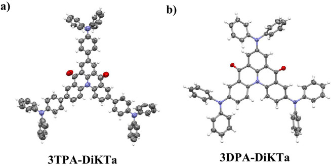
Thermal ellipsoid plot of the crystal structure of a) 3TPA‐DiKTa (CCDC number: 2183420) and b) 3DPA‐DiKTa (CCDC number: 2183421). Ellipsoids are drawn at the 50 % probability level and solvent molecules; minor components of disorder are omitted for clarity.
The nature of the lowest‐energy excited states can play a significant role in the color purity of the emitter. In particular, the narrowband of MR‐TADF emitters is conserved when the S1 state possesses SRCT, whereas the emission can broaden in some cases when the MR‐TADF core is decorated with donor groups due to the stabilization of the LRCT state that dominates in donor‐acceptor systems. [8] To gain insight into the relative energies of these states and to rationalize the optoelectronic properties of the emitters, the FMOs were first modelled at the optimized ground state geometry in the gas‐phase using the density functional theory (DFT) at the PBE0/6‐31G(d,p) level of theory. In contrast to the planarity values calculated from the X‐ray structures, those calculated from the DFT‐optimized structures show planarity differences between the two compounds (Figure S6). 3TPA‐DiKTa adopts a more planar conformation, with a planarity ratio of 74 %, compared to 3DPA‐DiKTa where the planarity ratio is 42 %. According to Figure S7, the LUMOs for both molecules are only distributed across the DiKTa core. Due to the introduction of the peripheral donors, the LUMOs of 3TPA‐DiKTa and 3DPA‐DiKTa are destabilized at −2.13 and −2.09 eV compared to that of DiKTa (−2.23 eV). The HOMO of DPA‐DiKTa is distributed across the entire molecule while the HOMO is mainly located on the peripheral TPA units in 3TPA‐DiKTa, which implies that this latter compound should possess a low‐lying LRCT state (Figure S7). The HOMO values (E HOMO) for 3TPA‐DiKTa and 3DPA‐DiKTa are −5.11 eV and −5.00 eV, respectively, which are significantly destabilized compared to that of DiKTa (E HOMO=−6.02 eV). The shallower HOMO and LUMO values for 3DPA‐DiKTa compared with 3TPA‐DiKTa are attributed to the stronger electron‐donating strength of DPA than TPA. The corresponding HOMO–LUMO gaps for 3DPA‐DiKTa and 3TPA‐DiKTa are of 2.91 and 2.98 eV, respectively. We have previously shown that DFT methods are not suitable for the accurate modelling of the excited states of MR‐TADF compounds. [15] We thus proceeded to model the excited states using the second order algebraic diagrammatic construction (ADC(2)) with the cc‐pVDZ basis set using the spin component scaling (SCS‐) approximation. The different density plots of the low‐lying singlet and triplet excited states are shown in Figure 3. The S1 difference densities of both emitters show similar patterns to that of DiKTa (Figures S4 and S7). Based on the charge‐transfer distance, DCT <0.6 Å, we assign these excited states to be SRCT (Table S3). For both emitters, there are small contributions to the difference density from the peripheral donors. Specifically, the difference density plot of 3DPA‐DiKTa indicates that the electron density is delocalized to the nitrogen atoms of DPA group, which will increase the electron‐donating strength, contributing to a more stabilized S1 state, while the decreased difference density of 3TPA‐DiKTa is mostly located on the phenyl rings of the TPA groups, thereby having less of an influence on the energy of the S1 state relative to the DPA groups in 3DPA‐DiKTa. The presence of the phenylene bridge between the DPA groups and the DiKTa core in 3TPA‐DiKTa reduces the HOMO and LUMO overlap but also increases the oscillator strength (f) in 3TPA‐DiKTa in comparison to 3DPA‐DiKTa (0.29 vs. 0.18, respectively). The S2 state of 3TPA‐DiKTa has a typical n‐π* character, while for 3DPA‐DiKTa S2 has similar difference density to S1. According to our previous study, the SRCT should dominate the S1 emission process under a low polarity environment.[ 8 , 16 ] The predicted S1/T1 energies for 3TPA‐DiKTa and 3DPA‐DiKTa are 3.16/2.93 and 2.72/2.46 eV, respectively, with corresponding ΔE ST values of 0.23 eV and 0.26 eV, which is similar to DiKTa (0.27 eV).
Figure 3.
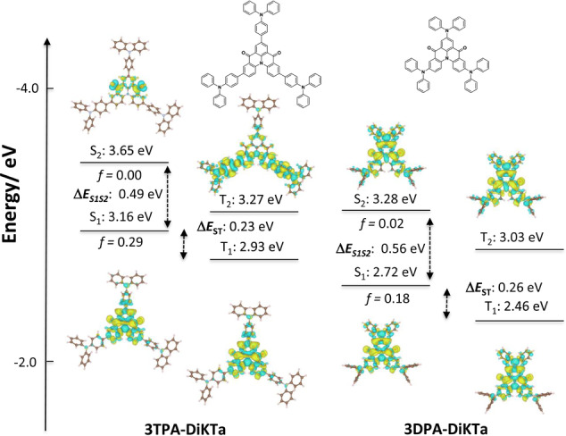
Difference density plots of S1/S2 and T1/T2 excited states (calculated in the gas phase at the SCS‐ADC(2)/cc‐pVDZ level) for 3TPA‐DiKTa and 3DPA‐DiKTa. f is the oscillator strength.
Cyclic voltammetry (CV) and differential pulse voltammetry (DPV) measurements were carried out in dichloromethane (DCM) to experimentally ascertain the HOMO and LUMO levels (Figure 4a). The electrochemical data is compiled in Table S4. The reduction waves of 3TPA‐DiKTa and 3DPA‐DiKTa are reversible and almost identical in potential to that of DiKTa. Based on the DFT calculations, the reduction is localized on the DiKTa core. The calculated LUMO levels are thus similar at −2.98 eV for 3TPA‐DiKTa and −3.01 eV for 3DPA‐DiKTa to at −3.00 eV for DiKTa. Both emitters also show reversible oxidation waves, which correspond to the oxidation of the peripheral amine donor units; 3DPA‐DiKTa shows two oxidation waves, reflecting unbalanced holes density distribution from the two electrochemically distinct DPA groups. The HOMO values of both emitters are destabilized at −5.13 eV for 3DPA‐DiKTa and −5.27 eV for 3TPA‐DiKTa compared to that of DiKTa at −6.12 eV. The trend in HOMO levels aligns with the DFT calculations (Table S2). The corresponding electrochemical gap for 3DPA‐DikTA is 2.12 eV and for 3TPA‐DiKTa is 2.29 eV, both significantly smaller than that of DiKTa at 3.12 eV.
Figure 4.
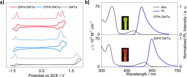
a) Cyclic voltammogram (CV) and differential pulse voltammetry (DPV) in degassed DCM with 0.1 M [nBu4N]PF6 as the supporting electrolyte and Fc/Fc+ as the internal reference (0.46 V vs. SCE). [21] b) Absorption and steady‐state PL spectra (SS) obtained in toluene at room temperature (λexc=340 nm). The inset are photographs of the photoluminescence from the toluene solution.
Spectroscopic measurements (absorption and photoluminescence) in dilute toluene (10−5 M) at room temperature were undertaken to understand the photophysical properties of the monomolecular species. The spectra are shown in Figure 4b. For both emitters the absorption band below 400 nm is attributed to a locally excited (LE) π–π* transition of the whole skeleton. [17] The longer wavelength SRCT absorption bands at 494 nm for 3TPA‐DiKTa and 554 nm for 3DPA‐DiKTa are red‐shifted compared to that of DiKTa at 433 nm. The PL maxima of 3DPA‐DiKTa occurs at 597 nm and 3TPA‐DiKTa occurs at 537 nm, both significantly red‐shifted compared to that of DiKTa (λPL=453 nm); indeed, 3DPA‐DiKTa shows the reddest emission among the DiKTa‐based MR emitters.[ 13 , 14 , 18 ] The Stokes shift of 3TPA‐DiKTa is 42 nm and of 3DPA‐DiKTa is 41 nm. The emission of both emitters is narrow, with FWHM of 54 nm or energy width at half maxima (EWHM) of 252 meV for 3TPA‐DiKTa and FWHM of 47 nm or EWHM of 168 meV for 3DPA‐DiKTa. These values reveal only a modest degree of reorganization in the excited state compared to the ground state. The slightly broader emission of 3TPA‐DiKTa than 3DPA‐DiKTa is due to a greater admixture of CT character to the SRCT emissive excited state. The EWHM value of 3DPA‐DiKTa is smaller than that of 3TPA‐DiKTa yet similar to that of DiKTa (172 meV or 27 nm), indicating the more pronounced LRCT character of excited state of 3TPA‐DiKTa, which aligns with the coupled cluster calculations analysis (Figure S22b). [19] Figure S19 shows the effect of oxygen on the steady‐state PL in toluene. The ΦPL values in degassed toluene are 44 % for 3TPA‐DiKTa and 59 % for 3DPA‐DiKTa, which decreased in the presence of oxygen to 33 % for 3TPA‐DiKTa and 38 % for 3DPA‐DiKTa, indicating that triplets play a significant role in the light emission process. [20] The time‐resolved PL in degassed toluene has mono‐exponential decay kinetics for both compounds, with PL lifetimes, τPL, of 11 ns for 3TPA‐DiKTa and 19 ns for 3DPA‐DiKTa, (Figure S20); no delayed emission was detected despite the oxygen sensitivity noted for the ΦPL. Thus, the contribution from the delayed fluorescence in 3TPA‐DiKTa and 3DPA‐DiKTa in toluene is smaller than we can reliably identify.
We next determined the singlet/triplet (S1/T1) energies of both emitters in 2‐MeTHF glass at 77 K (Figure S21). The S1/T1 energies are 2.48/2.27 eV for 3TPA‐DiKTa and 2.17/1.95 eV for 3DPA‐DiKTa, resulting in small ΔE ST values of 0.21 eV for 3TPA‐DiKTa and 0.22 eV for 3DPA‐DiKTa. These values are almost identical to that of DiKTa (≈0.20 eV) and its derivatives. [18] There is a notable small degree of positive solvatochromism observed for 3DPA‐DiKTa (Figure S22), which is characteristic of MR‐TADF compounds. There is a more pronounced positive solvatochromism for 3TPA‐DiKTa, consistent with a more significant admixture of CT character to the SRCT emissive excited state.
We next investigated the photophysical behavior of both emitters in the OLED relevant host, mCP, which has a suitably high triplet energy of 2.91 eV. [22] First, we identified 2 wt % as the optimal concentration by measuring the ΦPL of spin‐coated films of varying concentration from 1 wt % to 10 wt % in mCP. We then compared the ΦPL of 2 wt % films in a range of hosts such as bis[2‐(diphenylphosphino)phenyl]ether oxide (DPEPO) and 4,4′‐bis(9‐carbazolyl)‐1,1′‐biphenyl (CBP), and the ΦPL in mCP was found to be the highest at 86 %. (Figure S23). The ΦPL decreased along with a red‐shifted emission (Figure S24 and Table S6) upon an increase of the doping concentration of each emitter in mCP host. The red‐shifted emission can be ascribed in part to aggregate formation. As shown in Figure 5a, 3TPA‐DiKTa emits at λPL=551 nm with FWHM of 58 nm (245 meV) in 2 wt % mCP evaporated film, whereas 3DPA‐DiKTa shows a more red‐shifted emission at λPL=617 nm with FWHM of 56 nm (198 meV). Notably, their emission spectra in mCP are red‐shifted compared to those in dilute toluene, which given the low polarity of this host, implies the presence of host/guest interactions and likely contribution from aggregates in the solid state even at the low doping concentration employed. [23] Benefiting from the delicate balance between CT and SRCT, 3TPA‐DiKTa shows a higher ΦPL of 93 % than 3DPA‐DiKTa (ΦPL=60 %) in 2 wt % mCP evaporated film. The time‐resolved PL decays in mCP show a nanosecond prompt emission and a microsecond long delayed emission at room temperature (Table 1). 3TPA‐DiKTA possesses a shorter delayed lifetime, τDF, of 131 μs in comparison to 3DPA‐DiKTa (τDF of 323 μs) in 2 wt % mCP doped films (Figures 5c–d). The temperature‐dependent time‐resolved PL decays are shown in Figure S25. The prompt emission is insensitive to temperature while the delayed emission is thermally activated, the latter behavior consistent with TADF. Based on the quantum yield and lifetime of prompt and delayed fluorescence, the kinetic parameters of the two emitters were calculated according to the methodology described in our previous report (Table S7). [24] 3TPA‐DiKTa possesses a slower singlet radiation decay (k r s) of 1.98×10⁷ s−1 compared to that of 3DPA‐DiKTa (k r s=3.06×10⁷ s−1); these values are comparable to most of the reported MR‐TADF materials. [25] 3DPA‐DiKTa and 3TPA‐DiKTa possess slow reverse intersystem crossing rate constants (k RISC) of 0.14 and 2.49×10⁴ s−1, respectively, values that are not uncommon for MR‐TADF emitters. [26] The S1/T1 energies were determined from the onsets of the prompt fluorescence and phosphorescence spectra of 2 wt % mCP doped films of 3TPA‐DiKTa and 3DPA‐DiKTa at 77 K (Table 1). The ΔE ST value is 0.13 eV for 3TPA‐DiKTa and 0.20 eV for 3DPA‐DiKTa (Figure 5b). The former is smaller than that of DiKTa (0.20 eV) and accompanied by a shorter τDF, which is desirable for a TADF material.
Figure 5.
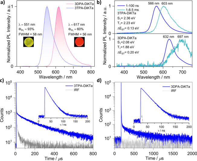
Photophysical properties of 3TPA‐DiKTa and 3DPA‐DiKTa in 2 wt % doped mCP films at room temperature. a) PL spectra (λexc=340 nm); b) prompt PL and phosphorescence spectra measurement (λexc=343 nm); c) and d) time‐resolved PL decays (λexc=379 nm). The inset are photographs of the photoluminescence from the films.
Table 1.
Photophysical data in 2 wt % doped mCP films.
|
Compound |
λPL [a] [nm] |
FWHM[b] [nm] |
ΦPL [c] [%] |
τp [d]; τd [d] [ns; μs] |
T1 [e] [eV] |
S1 [f] [eV] |
ΔE ST [g] [eV] |
|---|---|---|---|---|---|---|---|
|
DiKTa |
466 |
40 |
70 |
4.5, 168 |
2.55 |
2.75 |
0.20 |
|
3TPA‐DiKTa |
551 |
58 |
93 |
14, 131 |
2.23 |
2.36 |
0.13 |
|
3DPA‐DiKTa |
617 |
56 |
60 |
16, 323 |
1.88 |
2.08 |
0.20 |
[a] Obtained at 300 K, λexc=340 nm. [b] Full‐width at half‐maximum. [c] Photoluminescence quantum yield of thermally evaporated thin films, measured using an integrating sphere, under N2 at λexc=340 nm. [d] Measured at λexc=379 nm and 300 K under vacuum. [e] Obtained from the onset of the prompt spectrum (1–100 ns) at 77 K. [f] Obtained from the onset of the delayed spectrum (1–8.5 ms) at 77 K (λexc=343 nm). [g] ΔE ST=E(S1)−E(T1).
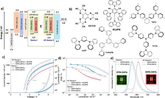
Based on the promising optoelectronic properties, we next proceeded to fabricate vacuum‐deposited OLEDs using 3TPA‐DiKTa and 3DPA‐DiKTa as emitters. As shown in Figure 6a and Figure S34, the optimized OLED stack (device I) consisted of: indium‐tin‐oxide (ITO, 112 nm)/1,4,5,8,9,11‐hexaazatriphenylenehexacarbonitrile (HATCN) (5 nm)/1,1‐bis[(di‐4‐tolylamino)phenyl]cyclohexane (TAPC) (40 nm)/tris(4‐carbazoyl‐9‐ylphenyl)amine (TCTA) (10 nm)/1,3‐bis(N‐carbazolyl)benzene (mCP) (10 nm)/emissive layer (20 nm)/1,3,5‐tri[(3‐pyridyl)‐phen‐3‐yl]benzene (TmPyPB) (50 nm) LiF (0.6 nm)/Al (100 nm), where HATCN is the hole injection layer (HIL), TAPC and TCTA play the role of hole transporting layers (HTL) and mCP acts as an electron/exciton blocking layer (EBL). TmPyPB acts both as an electron transport layer and a hole blocking layer due to its deep HOMO (−6.7 eV), [19] and LiF acts as an electron injection layer by modifying the work function of the aluminium cathode. The molecular structures of the materials used in these devices are shown in Figure 6b. The emission layer contained either 2 wt % of 3TPA‐DiKTa or 3DPA‐DiKTa doped into mCP host.
Figure 6.
a) Energy level diagram of materials employed in the devices, the red dotted box in HF device II indicates the energy levels of the assistant dopant 4CzIPN. b) Molecular structure of materials used in the devices. c) Current density and luminance versus voltage characteristics for the devices. d) External quantum efficiency versus luminance curves for the devices. e) Electroluminescence spectra of the devices, the inset is photograph images of the electroluminescence from the devices.
The performance of the OLEDs is summarized in Table S2 and S8 and device fabrication statistics are provided in Figure S33. Current density—voltage—luminance (J–V–L) curves, EQE–luminance curves, and electroluminescence spectra (EL) are shown in Figures 6c–e. Both OLEDs show narrow electroluminescence with a FWHM of 62 nm (267 meV) for the device with 3TPA‐DiKTa emitting at λEL of 551 nm and a FWHM is 60 nm (203 meV) for the device with 3DPA‐DiKTa emitting at λEL of 613 nm (Figure 6e). The EL spectra are similar to their corresponding PL spectra in the mCP doped thin film (Figure S27) reflecting an emission from the same SRCT excited state. In comparison to the previously reported OLED with DiKTa (λEL=465 nm, FWHM=39 nm), both of the devices showed a red‐shifted emission with a slightly broader electroluminescence. [7] As shown in Table S9 and Figure 7, compared to reported OLED devices with derivatives of DiKTa bearing peripheral electron‐donating groups, the 3TPA‐DiKTa‐based OLEDs showed red‐shifted emission while showing the best performance of green‐emitting ketone‐based MR‐TADF OLEDs. The 3DPA‐DiKTa‐based OLEDs are one of the highest‐efficiency red‐emissive devices containing a ketone‐based MR‐TADF emitters (Figure 7).[ 8 , 13 ] We note that, besides the DiKTa based red MR‐TADF OLEDs, there are only a small number of red MR‐TADF OLEDs. These include emitters based on BCz [10b] such as BBCZ‐tert‐butyl (5) (λEL=615 nm, FWHM=26 nm, EQEmax=22 %) and boron‐nitrogen embedded polycyclic heteroaromatics [27] such as R‐BN (λEL=664 nm, FWHM=48 nm, EQEmax=28.1 %) and R‐BNT (λEL=686 nm, FWHM=49 nm, EQEmax=27.6 %). The corresponding Commission Internationale de l’Éclairage (CIE) coordinates are (0.409, 0.577) and (0.633, 0.365) for the devices with 3TPA‐DiKTa and 3DPA‐DiKTa, respectively. The 3TPA‐DiKTa based device showed a much higher EQEmax in comparison to the device with 3DPA‐DiKTa as well as other reported DiKTa based devices (Table S9). The average over the set of 23 pixels of 3TPA‐DiKTa devices showed a EQEmax of 30.8 %, a maximum current efficiency (CEmax) of 117 cd/A, and maximum power efficiency (PEmax) of 108 lm W−1 at 1.45 cd m−2 (Table S2 and Figures S31–S32). Three of the 23 pixels showed recorded EQEmax close to 40 % at a luminance 1.84 cd m−2 (Figure S33). By contrast, the 3DPA‐DiKTa‐based device showed an EQEmax of 16.7 %, CEmax=28 cd A−1 and PEmax=27 lm W−1, the brightness only reached 8800 cd m−2 at an EQE of 1.3 % (Table 2, Figures 6 and S31–32). However, although OLEDs with both emitters show very high efficiency, serious efficiency roll‐off was observed where the external quantum efficiency at 100 cd m−2 (EQE100) of the devices with 3TPA‐DiKTa and 3DPA‐DiKTa reached only 18.1 % and 3.4 %, respectively. The long delayed lifetime and slow RISC rate contribute to increased triplet‐triplet annihilation and triplet‐polaron annihilation, both of which lead to efficiency roll‐off at higher current densities in the device. [28]
Figure 7.
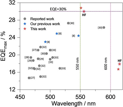
EQEmax of reported ketone‐based MR‐TADF OLEDs as a function of λEL (all the references in this Figure can be found in the Supporting Information).
Table 2.
Electroluminescence data for the devices.
|
Device |
λEL [c] [nm] |
FWHM[c] [nm] |
CIE[c] (x y) |
Von [d] [V] |
CEmax [cd A−1] |
PEmax [lm W−1] |
L max [e] [cd m−2] |
EQE[f] [%] |
|---|---|---|---|---|---|---|---|---|
|
Device I [a] | ||||||||
|
3TPA‐DiKTa |
551 |
62 |
0.409, 0.577 |
3.4 |
117 |
108 |
36 400 |
30.8/18.1/7.3 |
|
3DPA‐DiKTa |
613 |
60 |
0.633, 0.365 |
3.2 |
28 |
27 |
8800 |
16.7/3.4/1.9 |
|
HF Device II b | ||||||||
|---|---|---|---|---|---|---|---|---|
|
3TPA‐DiKTa |
556 |
70 |
0.424, 0.551 |
3.0 |
106 |
111 |
11 2190 |
30.0/27.4/20.0 |
|
3DPA‐DiKTa |
615 |
61 |
0.585, 0.396 |
3.0 |
35 |
37 |
46 003 |
17.9/8.7/6.0 |
[a] Device I; ITO/HATCN (5 nm)/TAPC (40 nm)/TCTA (10 nm)/mCP (10 nm)/emissive layer (2 wt % emitter in mCP, 20 nm)/TmPyPB (50 nm)/LiF (0.6 nm)/Al (100 nm. [b] HF Device II; ITO/HATCN (5 nm)/TAPC (40 nm)/TCTA (10 nm)/mCP (10 nm)/emissive layer (10 wt % 4CzIPN and 2 wt % emitter in mCP, 20 nm)/TmPyPB (50 nm)/LiF (0.6 nm)/Al (100 nm). [c] The electroluminescence maximum, CIE coordinates and FWHM of the EL spectrum recorded at 5 V. [d] The turn‐on voltage at EQEmax. [e] Luminance maximum (L max) measured at the highest voltage (9 V for device I and 8.4 V for device II). [f] The order of measured values: the EQEmax/EQE100/EQE1000.
To overcome the severe efficiency roll‐off, TADF‐sensitized‐fluorescence HF devices (HF device II) were fabricated. [29] Here, 4CzIPN was selected as the TADF assistant dopant because of its high ΦPL [30] and short τd of 3.0 μs in mCP (Figure S30) as well as the strong spectra overlap between the absorption spectra of 3TPA‐DiKTa and 3DPA‐DiKTa in toluene and the PL spectrum of 10 wt % 4CzIPN in mCP (Figure S28). Based on a concentration screen (Figure S29), the optimized ratio of mCP/4CzIPN/emitters was determined to be 88 : 10 : 2. The delayed lifetime of the 2 wt % 3TPA‐DiKTa:10 wt % 4CzIPN: 88 wt % mCP doped film is 3.3 μs, which is much shorter than that in doped film (131 μs) without the assist dopant. Based on this analysis, the HF device II contained an emissive layer consisting of 2 wt % 3TPA‐DiKTa or 2 wt % 3DPA‐DiKTa: 10 wt % 4CzIPN: 88 wt % mCP (Figure 6a). The device performances are shown in Figures 6 and S31–S32, and the data are summarized in Table 2. As shown in Figure 6e, the EL spectrum of the HF devices II with 3TPA‐DiKTa and 3DPA‐DiKTa are similar to the corresponding devices I. The HF devices II show an EQEmax of 30.0 % at λEL=556 nm (FWHM=70 nm) with 3TPA‐DiKTa as the terminal emitter, and an EQEmax of 17.9 % at λEL=615 nm (FWHM=61 nm) with 3DPA‐DiKTa as the terminal emitter, performances that are comparable to the analogous devices I (Table 2 and Figure 6). More significantly, the efficiency roll‐off was much improved for both HF devices II (Figure 6d and Table 2). The EQEs at 100 and 1000 cd m−2 in the HF devices II with 3TPA‐DiKTa are 27.4 % and 20.0 %, and with 3DPA‐DiKTa are 8.7 % and 6.0 %, respectively (Table 2). This corresponds to a significantly lower efficiency roll‐off from 41 % to 8.6 % for devices with 3TPA‐DiKTa and from 80 % to 51 % for devices with 3DPA‐DiKTa at 100 cd m−2, respectively. assuming 25 % out coupling efficiency, the EQEmax of the 3TPA‐DiKTa device is expected to be 23.3 %, which is much lower than the observed EQEmax of 30.8 % whilst the calculated EQEmax of the 3DPA‐DiKTa device is 15.0 %, and very close to the observed EQEmax of 16.7 %. One potential explanation of the much‐improved 3TPA‐DiKTa OLED efficiency would be that the transition dipole moment (TDM) of the emitter is preferentially horizontally oriented, parallel to the substrate surface. [31] We therefore measured the orientation of the TDM of the emitters in 2 wt % evaporated doped films in mCP of 50 nm thickness, emulating the thickness in the device. The angular dependent PL measurement results are shown in Figure 8 and used refractive index measurements and modelling are shown in Figure S1. The anisotropy factors, a, which is defined by the ratio of emitted power by vertical dipoles to total emitted power by all dipoles and extracted from the p‐polarized emission, were found to be 0.189 for 3TPA‐DiKTa, and 0.278 for 3DPA‐DiKTa; notably, previously reported DiKTa derivatives showed anisotropy factors close to isotropic at 0.33. [8] The relatively horizontal transition dipole moment orientation in 3TPA‐DiKTa is due to its high molecular weight and higher degree of planarity in contrast to 3DPA‐DiKTa (based on the DFT calculated optimized structure in the gas phase). [31] Considering the device structure and the measured anisotropic factors, the corresponding simulated out‐coupling efficiency calculated for 3TPA‐DiKTa is 28.3 % and for 3DPA‐DiKTa is 20.5 %. Combining the measured ΦPL of the films and the simulated outcoupling efficiencies, the calculated EQEmax values are 26.4 % for 3TPA‐DiKTa and 12.3 % for 3DPA‐DiKTa, which are slightly lower than the observed values. Therefore, the emitter orientation alone cannot explain this inconsistency. Similar higher than expected efficiencies of OLEDs have also been reported in many other MR‐TADF device studies. [8] Although the origin of the higher‐than‐expected EQEmax is not clear here, we can envision that a potential cause is the Purcell effect associated with the reflective electrodes in the OLED stack, which can result in a higher than expected IQE. [32] A second potential explanation could be microcavity effects in the OLED stack leading to light emission that is directed forwards more than for a Lambertian emitter and hence increasing the apparent EQE when measured from the forward direction. [8]
Figure 8.
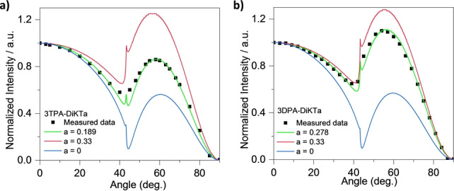
Measured PL intensity of the p‐polarized emission as a function of a rotation angle of mCP films doped with different emitters films at peak emission wavelength and comparison with simulated results: a) 3TPA‐DiKTa and b) 3DPA‐DikTa.
Conclusions
This study reports green and red‐emitting MR‐TADF compounds based on a DiKTa core. 3TPA‐DiKTa and 3DPA‐DiKTa show high ΦPL, moderate ΔE ST values of 0.13 and 0.20 eV, and long delayed lifetimes of 131 and 323 μs in 2 wt % doped mCP films, respectively. OLEDs using these MR‐TADF materials showed excellent performance with record‐high EQEmax of 30.8 % for ketone‐based MR‐TADF OLEDs in the case of the green‐emitting device with 3TPA‐DiKTa (λEL of 551 nm) and of 16.7 % for the red‐emitting device with 3DPA‐DiKTa (λEL of 613 nm). Efficiency roll‐off could be mitigated through the use of a hyperfluorescence device structure using 4CzIPN as an assistant dopant. An important contribution to the outstanding EQE of the 3TPA‐DiKTa is horizontal alignment of the transition dipole moment of the emitter in the evaporated film. These results demonstrate that simple decoration of the DiKTa acceptor with a TPA and DPA substituent is an effective approach to attaining efficient green/red TADF OLEDs.
Supporting Information
1H and 13C NMR spectra, HRMS and HPLC of all target compounds; supplementary computational data; supplementary photophysical data, supplementary devices data, and orientation measurement data.
Conflict of interest
The authors declare no conflict of interest.
1.
Supporting information
As a service to our authors and readers, this journal provides supporting information supplied by the authors. Such materials are peer reviewed and may be re‐organized for online delivery, but are not copy‐edited or typeset. Technical support issues arising from supporting information (other than missing files) should be addressed to the authors.
Supporting Information
Supporting Information
Acknowledgements
S. W. thanks the China Scholarship Council (201906250199). A. K. G. is grateful to the Royal Society for Newton International Fellowship NF171163. EZ‐C and IDWS acknowledge support from EPSRC (EP/L017008, EP/P010482/1). We are also grateful for financial support from the University of St Andrews Restarting Research Funding Scheme (SARRF) which is funded through the Scottish Funding Council grant reference SFC/AN/08/020. EZ‐C is a Royal Society Leverhulme Trust Senior Research fellow (SRF\R1\201089). We would also like to thank the Leverhulme Trust (RPG‐2016‐047) for financial support.
S. Wu, A. Kumar Gupta, K. Yoshida, J. Gong, D. Hall, D. B. Cordes, A. M. Z. Slawin, I. D. W. Samuel, E. Zysman-Colman, Angew. Chem. Int. Ed. 2022, 61, e202213697; Angew. Chem. 2022, 134, e202213697.
A previous version of this manuscript has been deposited on a preprint server (https://doi.org/10.26434/chemrxiv‐2022‐1j3np‐v2).
Contributor Information
Prof. Ifor D. W. Samuel, Email: idws@st-andrews.ac.uk.
Prof. Eli Zysman‐Colman, Email: eli.zysman-colman@st-andrews.ac.uk.
Data Availability Statement
The research data supporting this publication can be accessed at https://doi.org/10.17630/c6d59db2‐3168‐4152‐a520‐fe0d7012cca7
References
- 1. Arsenault A. C., Puzzo D. P., Manners I., Ozin G. A., Nat. Photonics 2007, 1, 468–472. [Google Scholar]
- 2.
- 2a. Dias F. B., Bourdakos K. N., Jankus V., Moss K. C., Kamtekar K. T., Bhalla V., Santos J., Bryce M. R., Monkman A. P., Adv. Mater. 2013, 25, 3707–3714; [DOI] [PubMed] [Google Scholar]
- 2b. Wong M. Y., Zysman-Colman E., Adv. Mater. 2017, 29, 1605444. [DOI] [PubMed] [Google Scholar]
- 3.
- 3a. Chen X. K., Tsuchiya Y., Ishikawa Y., Zhong C., Adachi C., Brédas J. L., Adv. Mater. 2017, 29, 1702767; [DOI] [PubMed] [Google Scholar]
- 3b. Dos Santos P. L., Ward J. S., Congrave D. G., Batsanov A. S., Eng J., Stacey J. E., Penfold T. J., Monkman A. P., Bryce M. R., Adv. Sci. 2018, 5, 1700989; [DOI] [PMC free article] [PubMed] [Google Scholar]
- 3c. Im Y., Kim M., Cho Y. J., Seo J.-A., Yook K. S., Lee J. Y., Chem. Mater. 2017, 29, 1946–1963; [Google Scholar]
- 3d. Huang J., Nie H., Zeng J., Zhuang Z., Gan S., Cai Y., Guo J., Su S. J., Zhao Z., Tang B. Z., Angew. Chem. Int. Ed. 2017, 56, 12971–12976; [DOI] [PubMed] [Google Scholar]; Angew. Chem. 2017, 129, 13151–13156. [Google Scholar]
- 4. Liu Y., Li C., Ren Z., Yan S., Bryce M. R., Nat. Rev. Mater. 2018, 3, 18020. [Google Scholar]
- 5.
- 5a. Santoro F., Lami A., Improta R., Bloino J., Barone V., J. Chem. Phys. 2008, 128, 224311; [DOI] [PubMed] [Google Scholar]
- 5b. Park I. S., Matsuo K., Aizawa N., Yasuda T., Adv. Funct. Mater. 2018, 28, 1802031; [Google Scholar]
- 5c. Kondo Y., Yoshiura K., Kitera S., Nishi H., Oda S., Gotoh H., Sasada Y., Yanai M., Hatakeyama T., Nat. Photonics 2019, 13, 678–682. [Google Scholar]
- 6. Hatakeyama T., Shiren K., Nakajima K., Nomura S., Nakatsuka S., Kinoshita K., Ni J., Ono Y., Ikuta T., Adv. Mater. 2016, 28, 2777–2781. [DOI] [PubMed] [Google Scholar]
- 7. Madayanad Suresh S., Hall D., Beljonne D., Olivier Y., Zysman-Colman E., Adv. Funct. Mater. 2020, 30, 1908677. [Google Scholar]
- 8. Wu S., Li W., Yoshida K., Hall D., Madayanad Suresh S., Sayner T., Gong J., Beljonne D., Olivier Y., Samuel I. D. W., Zysman-Colman E., ACS Appl. Mater. Interfaces 2022, 14, 22341–22352. [DOI] [PMC free article] [PubMed] [Google Scholar]
- 9. Zhang Y., Zhang D., Wei J., Liu Z., Lu Y., Duan L., Angew. Chem. Int. Ed. 2019, 58, 16912–16917; [DOI] [PubMed] [Google Scholar]; Angew. Chem. 2019, 131, 17068–17073. [Google Scholar]
- 10.
- 10a. Xu Y., Cheng Z., Li Z., Liang B., Wang J., Wei J., Zhang Z., Wang Y., Adv. Opt. Mater. 2020, 8, 1902142; [Google Scholar]
- 10b. Yang M., Park I. S., Yasuda T., J. Am. Chem. Soc. 2020, 142, 19468–19472; [DOI] [PubMed] [Google Scholar]
- 10c. Qi Y., Ning W., Zou Y., Cao X., Gong S., Yang C., Adv. Funct. Mater. 2021, 31, 2102017. [Google Scholar]
- 11. Liu Y., Xiao X., Ran Y., Bin Z., You J., Chem. Sci. 2021, 12, 9408–9412. [DOI] [PMC free article] [PubMed] [Google Scholar]
- 12. Yang M., Shikita S., Min H., Park I. S., Shibata H., Amanokura N., Yasuda T. J. A. F. M., Angew. Chem. Int. Ed. 2021, 60, 23142; [DOI] [PubMed] [Google Scholar]; Angew. Chem. 2021, 133, 23326. [Google Scholar]
- 13. Tsuchiya Y., Ishikawa Y., Lee S.-H., Chen X.-K., Brédas J.-L., Nakanotani H., Adachi C., Adv. Opt. Mater. 2021, 9, 2002174. [Google Scholar]
- 14. Fan X. C., Wang K., Shi Y. Z., Chen J. X., Huang F., Wang H., Hu Y. N., Tsuchiya Y., Ou X. M., Yu J., Adv. Opt. Mater. 2021, 10, 2101789. [Google Scholar]
- 15. Pershin A., Hall D., Lemaur V., Sancho-Garcia J.-C., Muccioli L., Zysman-Colman E., Beljonne D., Olivier Y., Nat. Commun. 2019, 10, 597. [DOI] [PMC free article] [PubMed] [Google Scholar]
- 16. Hall D., Sancho-García J. C., Pershin A., Ricci G., Beljonne D., Zysman-Colman E., Olivier Y., J. Chem. Theory Comput. 2022, 18, 4903–4918. [DOI] [PubMed] [Google Scholar]
- 17. Yuan Y., Tang X., Du X.-Y., Hu Y., Yu Y.-J., Jiang Z.-Q., Liao L.-S., Lee S.-T., Adv. Opt. Mater. 2019, 7, 1801536. [Google Scholar]
- 18. Huang F., Wang K., Shi Y.-Z., Fan X.-C., Zhang X., Yu J., Lee C.-S., Zhang X.-H., ACS Appl. Mater. Interfaces 2021, 13, 36089–36097. [DOI] [PubMed] [Google Scholar]
- 19. Hall D., Suresh S. M., dos Santos P. L., Duda E., Bagnich S., Pershin A., Rajamalli P., Cordes D. B., Slawin A. M. Z., Beljonne D., Köhler A., Samuel I. D. W., Olivier Y., Zysman-Colman E., Adv. Opt. Mater. 2020, 8, 1901627. [Google Scholar]
- 20.
- 20a. Tanaka H., Shizu K., Miyazaki H., Adachi C., Chem. Commun. 2012, 48, 11392–11394; [DOI] [PubMed] [Google Scholar]
- 20b. Kim D., Inada K., Zhao L., Komino T., Matsumoto N., Ribierre J.-C., Adachi C., J. Mater. Chem. C 2017, 5, 1216–1223. [Google Scholar]
- 21. Connelly N. G., Geiger W. E., Chem. Rev. 1996, 96, 877–910. [DOI] [PubMed] [Google Scholar]
- 22. Bagnich S. A., Rudnick A., Schroegel P., Strohriegl P., Köhler A., Philos. Trans. R. Soc. London Ser. A 2015, 373, 20140446. [DOI] [PMC free article] [PubMed] [Google Scholar]
- 23. Wu X., Su B.-K., Chen D.-G., Liu D., Wu C.-C., Huang Z.-X., Lin T.-C., Wu C.-H., Zhu M., Li E. Y., Nat. Photonics 2021, 15, 780–786. [Google Scholar]
- 24.
- 24a. Tsuchiya Y., Diesing S., Bencheikh F., Wada Y., dos Santos P. L., Kaji H., Zysman-Colman E., Samuel I. D. W., Adachi C., J. Phys. Chem. A 2021, 125, 8074–8089; [DOI] [PubMed] [Google Scholar]
- 24b. Masui K., Nakanotani H., Adachi C., Org. Electron. 2013, 14, 2721–2726. [Google Scholar]
- 25. Cai X., Xue J., Li C., Liang B., Ying A., Tan Y., Gong S., Wang Y., Angew. Chem. Int. Ed. 2022, 61, e202200337; [DOI] [PubMed] [Google Scholar]; Angew. Chem. 2022, 134, e202200337. [DOI] [PubMed] [Google Scholar]
- 26. Hall D., Stavrou K., Duda E., Danos A., Bagnich S., Warriner S., Slawin A. M. Z., Beljonne D., Köhler A., Monkman A., Olivier Y., Zysman-Colman E., Mater. Horiz. 2022, 9, 1068–1080. [DOI] [PubMed] [Google Scholar]
- 27. Zhang Y., Zhang D., Huang T., Gillett A. J., Liu Y., Hu D., Cui L., Bin Z., Li G., Wei J., Angew. Chem. Int. Ed. 2021, 60, 20498–20503; [DOI] [PubMed] [Google Scholar]; Angew. Chem. 2021, 133, 20661–20666. [Google Scholar]
- 28.
- 28a. Gupta A. K., Li W., Ruseckas A., Lian C., Carpenter-Warren C. L., Cordes D. B., Slawin A. M., Jacquemin D., Samuel I. D., Zysman-Colman E., ACS Appl. Mater. Interfaces 2021, 13, 15459–15474; [DOI] [PubMed] [Google Scholar]
- 28b. Giebink N. C., Forrest S., Phys. Rev. B 2008, 77, 235215; [Google Scholar]
- 28c. Schirra M., Schneider R., Reiser A., Prinz G., Feneberg M., Biskupek J., Kaiser U., Krill C., Thonke K., Sauer R., Phys. Rev. B 2008, 77, 125215. [Google Scholar]
- 29.
- 29a. Huang T., Wang Q., Xiao S., Zhang D., Zhang Y., Yin C., Yang D., Ma D., Wang Z., Duan L., Angew. Chem. Int. Ed. 2021, 60, 23771–23776; [DOI] [PubMed] [Google Scholar]; Angew. Chem. 2021, 133, 23964–23969; [Google Scholar]
- 29b. Chan C.-Y., Tanaka M., Lee Y.-T., Wong Y.-W., Nakanotani H., Hatakeyama T., Adachi C., Nat. Photonics 2021, 15, 203–207. [Google Scholar]
- 30. Sun J. W., Lee J.-H., Moon C.-K., Kim K.-H., Shin H., Kim J.-J., Adv. Mater. 2014, 26, 5684–5688. [DOI] [PubMed] [Google Scholar]
- 31. Tenopala-Carmona F., Lee O. S., Crovini E., Neferu A. M., Murawski C., Olivier Y., Zysman-Colman E., Gather M. C., Adv. Mater. 2021, 33, 2100677. [DOI] [PMC free article] [PubMed] [Google Scholar]
- 32. Zeng W., Lai H.-Y., Lee W.-K., Jiao M., Shiu Y.-J., Zhong C., Gong S., Zhou T., Xie G., Sarma M., Wong K.-T., Wu C.-C., Yang C., Adv. Mater. 2018, 30, 1704961. [DOI] [PubMed] [Google Scholar]
Associated Data
This section collects any data citations, data availability statements, or supplementary materials included in this article.
Supplementary Materials
As a service to our authors and readers, this journal provides supporting information supplied by the authors. Such materials are peer reviewed and may be re‐organized for online delivery, but are not copy‐edited or typeset. Technical support issues arising from supporting information (other than missing files) should be addressed to the authors.
Supporting Information
Supporting Information
Data Availability Statement
The research data supporting this publication can be accessed at https://doi.org/10.17630/c6d59db2‐3168‐4152‐a520‐fe0d7012cca7


