

Abstract
Objectives
Pulsed electric field (PEF) therapies employ punctuated energy delivery to kill cells in a volume of tissue through mechanisms that are not dependent on thermal processes. A key component to successful cardiac ablation procedures is ensuring the generation of transmural, contiguous ablation zones, which requires in‐depth knowledge regarding treatment sizes for a given therapeutic application.
Methods
In this study, a series of acute treatments were delivered to porcine ventricles, where triphenyl tetrazolium chloride (TTC) vitality stain was used to identify treatment effect sizes for the three focal monopolar CENTAURI PEF cardiac ablation energy settings.
Results
Treatment depths were 5.7, 7.2, and 8.2 mm for the 19, 22, and 25 A energy settings, respectively. Gross pathology indicated umbral zones of hemorrhage surrounded by pale avital TTC‐negative‐negative tissue, which contrasted significantly from radiofrequency ablation (RF) controls. Histologically, treatment zones are identified by regions of contraction band necrosis and cardiomyocytolysis, which contrasted with RF control lesions composed primarily of coagulation necrosis.
Conclusions
Together, these data indicate the ability for focal monopolar PEF treatments to generate deep treatment zones in cardiac ablation without incurring the gross or histological coagulative characteristics of RF thermal lesions.
Keywords: Aliya, CENTAURI, dose, electroporation, lesion, size
1. INTRODUCTION
Conventional thermal cardiac ablation techniques, such as radiofrequency (RF) ablation or cryothermy, involve the destruction of cardiac tissue through a thermal process. Despite progressive advances in the technology, the interacting electrically resistive and thermally conductive mechanisms continue to require operators to balance attaining transmural, contiguous lesions with the risk of thermal injury to surrounding extracardiac structures. Structures prone to such injury include the phrenic nerve, coronary vessels, and the esophagus.
Cardiac ablation using pulsed electric fields (PEFs) offers a new mechanism of ablation and cell death that is not dependent on thermal processes. This energy modality enables the destruction of cells without denaturing the stromal proteins that comprise the extracellular matrix. By preserving the structural proteins in tissue, it has been demonstrated that PEF ablation does not result in similar clinical sequelae from damage to sensitive and critical structures, including major vasculature and coronary vessels, the esophagus, pulmonary veins, and phrenic nerve. 1 , 2 , 3 , 4 , 5 , 6 , 7 , 8 , 9
Furthermore, the overall effect of PEF is not only dependent on the electric field distribution in the tissue, 10 , 11 but also on the electrode configuration of the ablation catheter. In bipolar electrode arrangements, energy is delivered across the tissue between two poles but can suffer considerable current loss to the blood pool. This usually results in relatively shallow contiguous lesions. 10 Alternatively, a monopolar PEF configuration places one pole of the electric field within the targeted ablation region and the other pole is a large electrode placed remote from the targeted site (e.g., a dispersive electrode patch). This configuration generates PEF ablation only at the ablation electrode and causes PEF energy to travel through the myocardium to the return electrode, resulting in deeper lesions. Because a focal monopolar electrode enables a greater range of lesion sizes, treatments should be titrated to address specific tissue characteristics and anatomical targets (higher energy settings for thick tissue and moderate settings for thinner tissue).
In contrast to RF ablation, there is little published data on expected lesion characteristics for a given set of PEF parameters and waveforms. This study characterizes lesions generated from the CENTAURI System (Galaxy Medical) used with a commercially available focal cardiac ablation catheter to deliver biphasic, monopolar PEF ablation at the three selectable energy settings.
2. METHODS
2.1. Animal prep and catheter lab equipment
This animal protocol was approved by the institutional animal care and use committee. Female Yorkshire swine (target weight 55–75 kg) were acquired and housed according to animal facility standard operating protocols. On the treatment day, pigs were sedated with Telazol at 4 mg/kg and Atropine at 0.02 mg/kg or Glycopyrrolate (0.01 mg/kg) given intramuscularly. A face mask administered Isoflurane (3%–5%) in oxygen for endotracheal intubation. Pigs were then maintained on Isoflurane general anesthesia (with 100% oxygen) as needed for the duration of the procedure. Pre‐emptive analgesia consisted of Carprofen (4 mg/kg) given IM. Pigs were placed supine. Femoral artery and venous access were obtained. Pigs were then given intermittent boluses of intravenous (IV) heparin to maintain an activated clotting time >250 s. They were also treated with IV bolus of 150 mg amiodarone followed by a continuous infusion (1 mg/min).
Surface and intracardiac electrocardiograms were monitored and recorded throughout the procedure using the EP recording system (CardioLab, General Electric). Intracardiac echocardiography (ICE) (ACUSON AcuNav™, Siemens) with a Vivid IQ ultrasound (General Electric) was used to guide catheter electrode placement and monitor for the generation of gaseous microemboli during PEF delivery. Fluoroscopy also guided catheter placement (Allura FD20; Philips).
Electroanatomical maps of the targeted chambers were first created using the Advisor HD‐Grid (Abbott) high‐density mapping catheter with the EnSite Precision Mapping System (Abbott) before introduction of the cardiac ablation catheter and any PEF ablations. The TactiSys™ Quartz (Abbott) was used to monitor contact force during treatment delivery.
2.2. CENTAURI PEF system
The PEF system in this study integrates within the electrophysiology laboratory environment in the same manner as a standard RF ablation system. The system includes a generator, a catheter interface box, a cardiac monitor, a dispersive electrode, electrocardiogram (ECG) electrodes, and all associated cabling (Figure 1). The interface box enables compatibility with multiple focal ablation catheters and electroanatomical mapping systems, including other 3.5 mm tip, open‐irrigated catheters. 12 For the purpose of this experiment, the 3.5 mm tip, open irrigated TactiCath SE catheter was used to deliver the monopolar, biphasic PEF energy for lesions (Figure 2).
Figure 1.
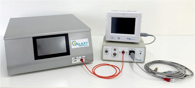
The Galaxy Medical CENTAURI System consists of the generator, the catheter connection box, and all associated cabling for the delivery of focal monopolar biphasic PEF energy at three distinct energy settings. PEF, pulsed electric field
Figure 2.
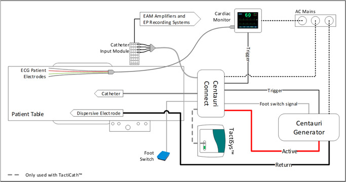
The PEF system set‐up and integration with standard electroanatomical mapping system, EP recording system, and the TactiCath SE cardiac ablation catheter. PEF, pulsed electric field
The study generator permits the selection of three PEF energy settings: denoted by their peak current of 19, 22, and 25 Amps, respectively. All three energy settings were tested in this study, with the operator selecting the targeted setting before initiating PEF delivery for each focal lesion. The generator operates with the cardiac monitor, which acts as a gating device to trigger from the intrinsic R‐wave and deliver PEF energy within the ST segment, minimizing chances for arrhythmia induction. While the cardiac gating and selected energy settings will both affect the duration of a PEF ablation delivery, ablations were generally delivered between 3 and 7 s in this study.
2.3. Treatment delivery
PEF treatments were targeted to the chamber walls of the right ventricle (RV) and left ventricle (LV) to ensure that ablation lesions could be fully characterized in three dimensions. A retrograde approach, with the ablation catheter, was used to access and deliver treatments to the LV. To access the RV, an Agilis NxT (Abbott) steerable sheath was used. The TactiCath SE catheter was flushed and irrigation through the catheter was set at 4 ml/min with heparinized saline and maintained at this constant rate throughout delivery of all PEF ablations. No neuromuscular paralytic was administered for any of the ablations.
The ablation catheter was placed at a targeted site in the ventricle with catheter orientation to attain sufficient stability, as perpendicular to the wall as possible, and target contact force (15–25 g). The target contact force range approximates the “Moderate” contact force range described for RF ablation in. 13 Immediately before PEF energy delivery, an ablation tag was placed on the mapping system. Ablation lesion tags were set to an 8 mm diameter on the mapping system to identify treated areas on the map and ensure treatment sites did not overlap. Green, orange, and red lesion tags were used to denote 19‐, 22‐, and 25‐Amp energy settings, respectively. The LV received ablations at all energy settings. The RV only received 19‐ and 22‐Amp ablations because it is thinner, and transmural effects would be excluded from the study.
The operator initiated and delivered the focal monopolar PEF treatment by depressing and holding the footswitch. After completion of PEF delivery, the footswitch was released. Surface and intracardiac electrograms were monitored during and after PEF delivery. ICE was monitored continuously for the occurrence of gaseous microemboli during PEF delivery. The operator then moved the ablation catheter to a new independent location, ensuring large separation between new and existing lesion tags. PEF ablations were delivered to the targeted LV or RV chamber walls until it was determined that there were no remaining suitable sites for adequate lesion separation.
In addition, to investigate the characteristic differences in lesion gross pathology and histopathology between the PEF tested here and conventional RF ablation, a small sample of RF lesions were generated using the TactiCath SE according to manufacturer instructions in the LV (n = 3) and RV (n = 3). The RF lesions were created using a power of 25 W for 60 s, with 25 g of force and 17 ml/min of irrigation, for comparison with published findings. 13 Because this dose is already described in the literature, these ablations were not used for lesion size comparisons.
2.4. Tissue processing and data collection
Lesion dimensions were assessed acutely using well established and reproducible methods that have been validated and published. 10 , 14 , 15 A minimum 2‐h dwell period was initiated to allow adequate time for visible lesion formation. 16 , 17 Animals were given a 10 000 IU bolus IV heparin to prevent blood clotting and an IV infusion of 3.5 g triphenyl tetrazolium chloride (TTC) in 10 ml of saline (or 250 ml of 1% TTC) was administered and allowed to perfuse through the animal circulatory system for 15 min. Animals were then euthanized with KCl overdose (1–2 mEq/kg) as per standard procedures of the animal facility to further reduce the confounding effects of blood clotting.
During necropsy, the heart and lungs were explanted en bloc, and observed grossly for any abnormal findings. The heart‐lung complex was retrograde gravity‐perfused through the aorta with 500 ml of heparinized saline to flush out any remaining blood. This was followed by an infusion of 500 ml of 10% neutral buffered formalin for 1 h to preserve the anatomical shape of the heart during fixation.
A minimum 2‐day fixation period was provided before sectioning. Following this period, the heart was sliced into 2 mm thick slices from the apex to the atria, and treatment sites were identified and measured for depth and width. All treatment measurements were recorded, and representative tissues were sent to histopathology for review and characterization. Treatment sites were then correlated with the electroanatomical map to identify each PEF and RF ablation and associate it with the corresponding lesion tag number (Figure 3). Transmural lesions were excluded from measurement.
Figure 3.
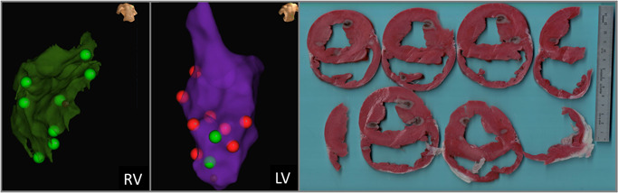
Matching EnSite Precision treatment sites with gross pathology treatment effects. The maps and anatomical landmarks were used to delineate respective treatments. Here, green lesions tags denote where the 19 Amp energy setting was used, while red lesion tags denote the 25 Amp energy setting.
2.5. Statistical analysis
All results are presented as a mean ± standard deviation. Lesion depth and widths according to current setting were compared using one‐sided analysis of variance analysis. A p < .05 was considered significant. Statistical analyses were performed using Prism 9.3 (Graphpad).
3. RESULTS
3.1. Treatment effects
A total of four swine (61.7–67.7 kg) received a net 65 independent focal PEF ablations in the RV and LV. Outside of the detectable microbubbles from the 4 ml/min baseline irrigation, there were no incidences of PEF‐induced gaseous microemboli on ICE during any of the ablations. Muscle contractions were monitored for, but not observed during PEF delivery. There were no occurrences of notable ECG change (ST elevation, tachycardia, fibrillation) following PEF ablation, nor any noted changes in resting heart rate. Local intracardiac ECG signals were immediately attenuated to varying degree following PEF ablation, which may reflect contribution from the tissue “stun” effect. 10 There were no indications of catheter breakdown during delivery, nor visible defects to catheter integrity noted following treatment delivery to each pig.
Following euthanasia and necropsy, treatment sites were readily identifiable and able to be correlated with electroanatomical mapping treatment sites (Figure 3). Treatment sites that could not be definitively paired with a treatment delivery and energy setting (due to tissue characteristics, slicing techniques, or overlapping treatment zones) were excluded. After tissue processing, 48 treatment zones were identified and able to be positively correlated with a corresponding lesion tag for analysis in this study (13 in RV, 35 in LV).
Treatment sites were clearly visible and defined by an inner hemorrhagic zone surrounded by a penumbra of avital, TTC‐negative tissue, comprising the extent of the lesion (Figure 4). This contrasts markedly from the representative RF lesions, which are identified by a core of brown and tan tissue, surrounded by a rim of hemorrhage. Furthermore, Figures 3 and 4 demonstrate that qualitatively, the lesion shape appears more cylindrical than the typical hemispherical shape observed with RF. 13
Figure 4.
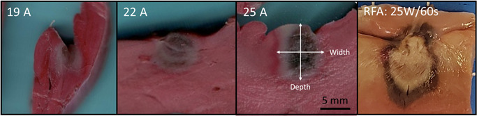
Representative acute (>2 h) gross pathology results from the three energy settings. TTC stained vital tissue red, while avital tissue is pale. An umbral region of acute hemorrhage is identifiable, which was observed to resolve 3 days after PEF delivery (data not shown). A panel of a representative acute RFA ventricle lesion (25 W, 60 s, 25 g of contact force, with 17 ml/min irrigation) is included to demonstrate the clear difference between monopolar PEF energy and thermal ablation modalities, where a large core of tan and brown tissue is found, surrounded by a penumbra of hemorrhage. TTC, triphenyl tetrazolium chloride
Histologically, acute treatment zones showed regions of contraction band necrosis representative of hypercontraction consistent with massive calcium influx and cardiomyocytolysis (Figure 5). These histological characteristics are distinct from the representative RF lesions, which were comprised of a large inner volume of coagulation necrosis surrounded by a rim region with cardiomyocytolysis and interstitial hemorrhage.
Figure 5.
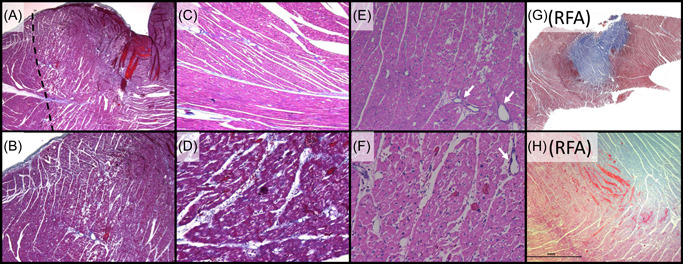
Characteristic histology for the acute monopolar PEF system tested relative to RFA lesions with (A–D, G, H) Masson's Trichrome and (E, F) Hematoxylin and Eosin. (A) Low power magnification (×2) of a left ventricle lesion, demonstrating a focal ablation site characterized by acute myocardial necrosis in the treated area (right of dashed line). (B) Higher magnification (×4) of Panel A, demonstrating the transition zone between necrotic and viable myocytes. (C) Adjacent control (untreated) tissue (×10), which contrasts with (D) the treatment (×20) showing acute contraction band necrosis. (E: ×10, F: ×20) lesion region showing myocyte contraction, hypereosinophilia, and cardiomyocytolysis “moth eaten” appearance of necrotic muscle, with interspersed intact blood vessels (arrows). (G) Low power magnification of a left ventricle RFA lesion characterized by a large zone of coagulation necrosis (blue) surrounded by a penumbra of hemorrhagic contraction band necrosis (dark purple). (F) Higher magnification of the boundary zone, further contrasting the difference in lesion histopathology between Galaxy PEF treatments and RF thermal ablation. (A): Low mag Tri lesion boundary. (B): Mid‐mag Tri lesion boundary. (C): Control Mid‐high zoom. (D): High zoom lesion CBN. (E): Midhigh‐mag HE lesion (myocytolysis). (F): High mag HE lesion. (G): low mag RF. (H): mid‐mag RF. PEF, pulsed electric field; RF, radiofrequency
3.2. Ablation lesion dimensions
Average ablation lesion depths were 5.7 ± 1.5 mm (n = 14), 7.2 ± 2.0 mm (n = 16), and 8.2 ± 1.6 mm (n = 18) for the 19‐, 22‐, and 25‐Amp energy settings, respectively (p < .001). Lesion depths were generally greater than or equal to average lesion widths, which were 5.8 ± 1.6 mm, 7.0 ± 1.7 mm, and 7.2 ± 1.6 mm for the 19‐, 22‐, and 25‐Amp energy settings, respectively (p = .041). Compiling these dimensions with the half‐ellipsoid formula for volume (V = 0.5 × (4/3 × π × w2 × d)), average treatment volumes were thus 50.2, 92.4, and 111.3 mm3, respectively. Lesion depths and widths are shown relative to typical published RF lesion dimensions in Figure 6 and Table 1.
Figure 6.
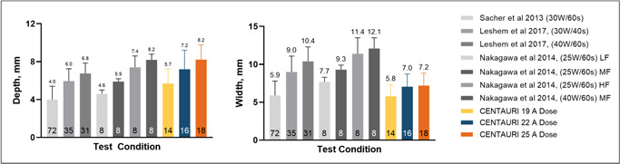
Comparing focal monopolar PEF ventricle ablation depths (left) and widths (right) with RF. 13 , 18 , 19 RF contact forces indicated by low force (LF, 3–8 g), medium force (MF, 18–27 g), and high force (HF, 40–62 g). Trial numbers for each test condition are indicated inside the bars. PEF, pulsed electric field; RF, radiofrequency
Table 1.
Treatment outcomes a
| Technology | Energy settings | Contact force, g | Treatment depth, mm | Treatment width, mm | Calculated volume, mm 3 |
|---|---|---|---|---|---|
| PEF | 19 A | 20.7 ± 11.8 | 5.7 ± 1.5 | 5.8 ± 1.6 | 50.2 |
| PEF | 22 A | 28.1 ± 8.4 | 7.2 ± 2.0 | 7.0 ± 1.7 | 92.4 |
| PEF | 25 A | 24.8 ± 11.5 | 8.2 ± 1.6 | 7.2 ± 1.6 | 111.3 |
| RF | 25 W/60 s | 23.7 ± 7.1 | 5.9 ± 0.7 | 9.3 ± 0.7 | 133 |
Abbreviations: PEF, pulsed electric field; RF, radiofrequency.
Values provided as average ± standard deviation.
4. DISCUSSION
This study examined the lesion dimensions of focal PEF ablation produced using the CENTAURI System in a preclinical model at three energy settings. The system uses a focal monopolar approach to obtain deeper lesions than those readily attainable by bipolar electrode configurations. Treatment sites were delivered and guided with a commercially available cardiac ablation catheter and mapping system. ICE was continuously monitored during PEF ablations, and while the constant 4 ml/min irrigation rate produced a small baseline of microbubbles on ICE, there was no observable burst of microbubbles during PEF delivery.
Intracardiac ECG signals were attenuated to varying degrees immediately post‐PEF at each treatment site. However, as described in, 10 , 20 there is likely contribution to the signal attenuation from a tissue “stun” effect. This stun effect is produced by all PEF technologies when sub‐lethal doses alter cardiomyocyte conduction properties while the cells and tissue recover, which occur over several hours. 17 Because the stun zone is larger than the final treatment effect size, complete attenuation or acute isolation of intracardiac voltage signals is readily attained with PEF, resulting in false positives. It is, therefore, inappropriate to draw efficacy conclusions from immediate ECG changes following PEF delivery. Lesion size is generally more informative to the safety and efficacy characteristics of the technology. Future studies may explore whether variable ECG signal attenuation occurs with the tested PEF system, and if this is correlated to energy settings and tissue thickness at each treatment site.
It was thus shown in 21 that contact presence plays a role in ablation zone, with contact force also having a meaningful impact, albeit less sensitive than for RF ablation. Changes in electrode orientation will depend on the geometry of the catheter, including active electrode length, but presumably reflect the contact force component perpendicular to the tissue. Future investigations may expand on this data set to determine the influence of catheter orientation.
Grossly, PEF focal ablations resulted in TTC‐negative regions of avital tissue, with a core of hemorrhage presumably from capillary endothelium disruption, and an outer rim of hyperstained tissue consistent with reversibly damaged cellular recovery. 22 The three available energy settings produced lesions in the range of 5.7–8.2 mm deep and 5.8–7.2 mm wide. Whereas the intent of the data presented here is to characterize the effects of the commercially available settings, no higher energy settings were evaluated in this study. It is well described that additional activations generate larger lesions with diminishing returns. 10 , 16 , 23 Future studies may investigate the extent that additional activations further increase treatment size, and investigate any potential accumulated differences in histological characteristics.
The flexibility of multiple energy settings and their associated treatment effects enables clinicians to target tissue characteristics and anatomical variations, accordingly, enabling treatment for a wide array of potential cardiac ablation targets. Different anatomical cardiac ablation objectives may include pulmonary vein isolation (1–4 mm), cavotricuspid isthmus (4–8 mm), and ventricular tachycardia (6–10 mm). 24 , 25 , 26 , 27 Furthermore, the focal nature of PEF ablation with the system studied here provides clinicians an additional degree of flexibility, offering the ability to generate custom‐designed lines and regions of ablation, as well as by permitting larger inter‐lesion distances for thinner targets and closer inter‐lesion distances for thicker targets.
The application of intracardiac PEF ablation has resulted in occasional observation of vasospasm clinically, 28 which was associated with ST elevation in a patient. It was noted that there was no incidence of arrhythmia, including no ST elevation, during and following PEF treatment delivery in this study. Future PEF studies should continue to elucidate the susceptibility and interventional options for managing PEF‐induced vasospasm. This is particularly pertinent given the flexibility and deep treatment effects of the PEF technology tested here.
These results were obtained by connecting the PEF generator to a standard, commercially available 3.5 mm tip open irrigated ablation catheter, in this case the TactiCath SE. Notably, this system has also been demonstrated clinically to be compatible with other commercially available cardiac ablation catheters and electroanatomical systems. 12 , 29 Given that most available open irrigated, contact force catheters are similar in design (e.g., 3.5 mm tip with proximal rings for voltage measurements), it is reasonable to infer that the lesion sizes reported in this study would apply to other similar ablation catheter designs.
The histological findings produced by this PEF system are markedly distinct from the published treatment characteristics of thermal ablation. 30 Grossly, the PEF treatments resulted in TTC‐negative regions of avital tissue with a core of hemorrhage, presumably from capillary endothelium disruption causing microvascular obstruction and blood cell/hemosiderin extravasation. The outer rim of hyperstained tissue is consistent with reversibly damaged cellular recovery. Subjectively, there was no difference in resistance to cutting between the treated and untreated tissue regions, presumably due to the absence of coagulated extracellular proteins. 31 Conversely, focal RF lesions often exhibit a tan to brown treatment zone surrounded by a dark rim, 30 consistent with the RF lesions produced in this study for comparison. Histologically, the PEF treatment zones in this study were primarily indicated by contraction band necrosis and cardiomyocytolysis, which was readily apparent with Masson's Trichrome stain. Conversely, thermal ablation zones are characterized by pronounced coagulation necrosis of cardiomyocytes, with edema and hemorrhage surrounding individual cells. 30 This was consistent with the comparator RF lesions produced in this study, which exhibited a large core of coagulation necrosis surrounded by a rim of hemorrhage and cardiomyocytolysis. These differences further affirm the distinction between the PEF system evaluated here and thermally‐dependent ablation techniques. 32
In theory, the monopolar transmission of energy used in this study could increase the propensity for skeletal muscle contraction, since the current returns via the torso to the dispersive patch electrode. 33 To mitigate this, the system studied uses biphasic waveform, 34 , 35 enabling dramatically reduced muscle contraction during treatments over a wide range of energy settings. This allows the generation of clinically valuable monopolar PEF lesion sizes without treatment‐altering muscle contraction. Furthermore, a smaller focal catheter tip requires less net current delivered to the patient than larger surface area catheters to achieve the same treatment effect depth, providing another means for reducing muscle contraction. These hypotheses are supported by the data produced here, where no skeletal muscle contractions were noted during PEF delivery in the ventricles. Finally, the monopolar PEF waveform used in the system has been designed to limit the risk of electrode breakdown, barotrauma, gaseous microemboli, coagulum formation, and Joule heating effects which may be present in other monopolar technologies 36 , 37 and may be related to undesirable clinical sequelae such as cerebral ischemic events. 38
5. STUDY LIMITATIONS
The scope of this study has several limitations, most notably the acute nature of ablation zone assessments. The time course of gross and histopathological PEF treatment effects in cardiac tissue has been described elsewhere. 10 Furthermore, safety of the tested technology and PEF in general in relation to sensitive structures such as blood vessels and nerves are described in. 10 , 39 Broadly, PEF histology shows dead cardiomyocytes are replaced by fibroblast infiltration, resulting in a fibrotic scar replacement of the treated zones over the course of 2–4 weeks. While maximum treatment measurements may be influenced by late‐stage cell death onset over a short‐term (hours‐days), which may influence treatment measurements, this study sought to compare PEF lesion sizes under the same conditions as conventional RF ablation studies. It was thus not an objective of this study to evaluate the temporal evolution of these treatment effects on a longer timescale.
Another limitation of this study is that only one focal ablation catheter was tested with the system. However, other compatible catheters all utilize approximately the same materials and dimensional characteristics of the distal tip electrode. Therefore, while some minor differences in irrigation design, contact force, and mapping accuracy may be experienced between catheters, it is reasonable to expect that lesion dimensions will be similar when using this PEF system with focal ablation catheters of similar dimension and design.
An additional consideration is the exclusive evaluation of treatment size in ventricular tissue. Ablations were performed in the ventricles to reduce the occurrence of transmural lesions, permitting more accurate measurement of the resulting treatment depth. Notably, most amenable cardiac ablation targets reside within the atria. Presently, there is no evidence to suggest that cardiomyocyte PEF susceptibility changes between these two chambers, and thus it is likely that the treatment depths reported here will adequately reflect treatment depths in atrial tissue targets. For ventricular ablation objectives, namely targeting ventricular tachycardia, the treatment effect in relation to fibrotic scar tissue remain a topic of active research. 40
Additional notes regarding the use of ventricles in this study include the trabeculated anatomy of the ventricles makes it a challenging location for assessment of treatment size, contributing to the considerable standard deviations in measured dimensions. Furthermore, the motile nature of the ventricles makes contact force markedly less stable. However, tested contact force was limited to a range of 15–25 g, and since PEFs were gated to the R‐wave, the deliveries were synchronized to be delivered while the ventricles are in systole, providing more consistent contact force during PEF delivery. 21
6. CONCLUSIONS
This paper reports the gross, histologic, and dimensional characteristics of cardiac lesions created with the three programmable CENTAURI PEF energy settings delivered in vivo to swine endocardial ventricular tissue. The system was used with a commercially available focal ablation catheter under the guidance of a commercially available electroanatomical mapping system. Lesions show a dark hemorrhagic region is surrounded by a TTC‐negative region, which is further surrounded by a hyperstained rim. Histologically, the treatments are predominantly characterized by contraction band necrosis, versus the distinct coagulation necrosis found from thermal ablation. Treatment zones were generally cylindrical in shape and average dimensions for the three energy settings ranged between 5.7 and 8.2 mm deep (p < .001) and 5.8–7.2 mm wide (p = .041). These data demonstrate the ability to titrate dosing with focal monopolar biphasic PEF ablation, enabling targeting of both thin and thick tissue targets throughout the cardiac anatomy.
CONFLICTS OF INTEREST
Dr. Verma reports grants from Bayer, Biosense Webster, Abbott, and Medtronic; advisory for Biosense Webster, Medtronic, Boston Scientific, Adagio Medical, Medlumics, and Ablacon; research with Galaxy Medical. Drs. Neal, Vachani, and Evans are researchers with Galaxy Medical. Dr. Deneke reports advisory for Galaxy Medical and Farapulse; Dr. Nakagawa reports research for Biosense Webster, Galaxy Medical.
ACKNOWLEDGMENT
This work is supported by Galaxy Medical.
Verma A, Neal R, Evans J, et al. Characteristics of pulsed electric field cardiac ablation porcine treatment zones with a focal catheter. J Cardiovasc Electrophysiol. 2023;34:99‐107. 10.1111/jce.15734
DATA AVAILABILITY STATEMENT
Research data are not shared.
REFERENCES
- 1. Stewart MT, Haines DE, Miklavčič D, et al. Safety and chronic lesion characterization of pulsed field ablation in a Porcine model. J Cardiovasc Electrophysiol. 2021;32:958‐969. 10.1111/jce.14980 [DOI] [PMC free article] [PubMed] [Google Scholar]
- 2. Rubinsky B, Onik G, Mikus P. Irreversible electroporation: a new ablation modality—clinical implications. Technol Cancer Res Treat. 2007;6(no. 1):37‐48. 10.1177/153303460700600106 [DOI] [PubMed] [Google Scholar]
- 3. Maor E, Ivorra A, Leor J, Rubinsky B. The effect of irreversible electroporation on blood vessels. Technol Cancer Res Treat. 2007;6(no. 4):307‐312. 10.1177/153303460700600407 [DOI] [PubMed] [Google Scholar]
- 4. du Pré BC, van Driel VJ, van Wessel H, et al. Minimal coronary artery damage by myocardial electroporation ablation. EP Europace. 2013;15(no. 1):144‐149. 10.1093/europace/eus171 [DOI] [PubMed] [Google Scholar]
- 5. Song Y, Zheng J. The esophagus survives non‐thermal irreversible electroporation ablation and gradually rehabilitates. In Review, preprint. 2020:1‐15. 10.21203/rs.3.rs-18960/v1 [DOI] [Google Scholar]
- 6. Neven K, van Es R, van Driel V, et al. Acute and long‐term effects of full‐power electroporation ablation directly on the porcine esophagus. Circ Arrhythm Electrophysiol. 2017;10(5):e004672. 10.1161/CIRCEP.116.004672 [DOI] [PubMed] [Google Scholar]
- 7. Howard B, Haines DE, Verma A, et al. Reduction in pulmonary vein stenosis and collateral damage with pulsed field ablation compared with radiofrequency ablation in a canine model. Circ Arrhythm Electrophysiol. 2020;13(9):e008337. 10.1161/CIRCEP.120.008337 [DOI] [PMC free article] [PubMed] [Google Scholar]
- 8. van Driel VJHM, Neven K, van Wessel H, Vink A, Doevendans PAFM, Wittkampf FHM. “Low vulnerability of the right phrenic nerve to electroporation ablation. Heart Rhythm. 2015;12(no. 8):1838‐1844. 10.1016/j.hrthm.2015.05.012 [DOI] [PubMed] [Google Scholar]
- 9. Li W, Fan Q, Ji Z, Qiu X, Li Z. The effects of irreversible electroporation (IRE) on nerves. PLoS One. 2011;6(no. 4):e18831. 10.1371/journal.pone.0018831 [DOI] [PMC free article] [PubMed] [Google Scholar]
- 10. Verma A, Asivatham SJ, Deneke T, Castellvi Q, Neal RE. Primer on pulsed electrical field ablation: understanding the benefits and limitations. Circ Arrhythm Electrophysiol. 2021;14:e010086. 10.1161/CIRCEP.121.010086 [DOI] [PubMed] [Google Scholar]
- 11. Batista Napotnik T, Polajžer T, Miklavčič D. Cell death due to electroporation—a review. Bioelectrochemistry. 2021;141:107871. 10.1016/j.bioelechem.2021.107871 [DOI] [PubMed] [Google Scholar]
- 12. Verma A, Khaykin Y, Sanchez‐Samonte P, Kittichamroen JN, “Pulmonary Vein Isolation (PVI) and Posterior Wall Isolation (PWI) for Atrial Fibrillation Using Adjustable Focal Pulsed Electric Fields: SPACE AF Acute Results,” presented at the Heart Rhythm; 2022, San Francisco, CA: Apr. 2022. [Google Scholar]
- 13. Nakagawa H, Jackman WM. The Role Of Contact Force In Atrial Fibrillation Ablation. 2014;vol. 7(no. 1):7. [DOI] [PMC free article] [PubMed] [Google Scholar]
- 14. Ben‐David E, Appelbaum L, Sosna J, Nissenbaum I, Goldberg SN. Characterization of irreversible electroporation ablation in in vivo porcine liver. Am J Roentgenol. 2012;198(no. 1):W62‐W68. 10.2214/AJR.11.6940 [DOI] [PubMed] [Google Scholar]
- 15. Maor E, Sugrue A, Witt C, et al. Pulsed electric fields for cardiac ablation and beyond: a state‐of‐the‐art review. Heart Rhythm. 2019;16(no. 7):1112‐1120. 10.1016/j.hrthm.2019.01.012 [DOI] [PubMed] [Google Scholar]
- 16. Appelbaum L, Ben‐David E, Sosna J, Nissenbaum Y, Goldberg SN. US findings after irreversible electroporation ablation: radiologic‐pathologic correlation. Radiology. 2012;262(no. 1):117‐125. 10.1148/radiol.11110475 [DOI] [PubMed] [Google Scholar]
- 17. Nakagawa H, et al., “Temporal and Spatial Evolution of Reversible and Irreversible Ventricular Lesion Boundaries Produced by Pulsed Electric Field Ablation,” presented at the Heart Rhythm 2022, San Francisco, CA, 2022. [Google Scholar]
- 18. Sacher F, Wright M, Derval N, et al. Endocardial versus epicardial ventricular radiofrequency ablation: utility of in vivo contact force assessment. Circ Arrhythm Electrophysiol. 2013;6(no. 1):144‐150. 10.1161/CIRCEP.111.974501 [DOI] [PubMed] [Google Scholar]
- 19. Leshem E, Tschabrunn CM, Contreras‐Valdes FM, Zilberman I, Anter E. Evaluation of ablation catheter technology: comparison between thigh preparation model and an in vivo beating heart. Heart Rhythm. 2017;14(no. 8):1234‐1240. 10.1016/j.hrthm.2017.04.035 [DOI] [PMC free article] [PubMed] [Google Scholar]
- 20. van Zyl M, Ladejobi AO, Tri JA, et al. Reversible atrioventricular conduction impairment following bipolar nanosecond electroporation of the interventricular septum. JACC: Clinical Electrophysiology. 2021;7(no. 2):255‐257. 10.1016/j.jacep.2020.10.004 [DOI] [PubMed] [Google Scholar]
- 21. Nakagawa H, Castellví Q, Neal RE II. Effects of contact force on lesion size during pulsed field ablation. Presented at the Heart Rhythm. 2021:2021.
- 22. Nakagawa H, Castellvi Q, Neal RE II. Histological characterization of reversible and irreversible ventricular lesion boundaries produced by pulsed field ablation. presented at the Heart Rhythm. 2021:2021.
- 23. Miklovic T, Latouche EL, DeWitt MR, Davalos RV, Sano MB. A comprehensive characterization of parameters affecting high‐frequency irreversible electroporation lesions. Ann Biomed Eng. 2017;45(no. 11):2524‐2534. 10.1007/s10439-017-1889-2 [DOI] [PubMed] [Google Scholar]
- 24. Piątek‐Koziej K, Hołda J, Tyrak K, et al. Anatomy of the left atrial ridge (coumadin ridge) and possible clinical implications for cardiovascular imaging and invasive procedures. J Cardiovasc Electrophysiol. 2020;31(no. 1):220‐226. 10.1111/jce.14307 [DOI] [PubMed] [Google Scholar]
- 25. Kawel N, Turkbey EB, Carr JJ, et al. Normal left ventricular myocardial thickness for middle‐aged and older subjects with steady‐state free precession cardiac magnetic resonance: the multi‐ethnic study of atherosclerosis. Circulation: Cardiovascular Imaging. 2012;5(no. 4):500‐508. 10.1161/CIRCIMAGING.112.973560 [DOI] [PMC free article] [PubMed] [Google Scholar]
- 26. Whitaker J, Rajani R, Chubb H, et al. The role of myocardial wall thickness in atrial arrhythmogenesis. Europace. 2016;18(12):1758‐1772. 10.1093/europace/euw014 [DOI] [PMC free article] [PubMed] [Google Scholar]
- 27. Saremi F, Pourzand L, Krishnan S, et al. Right atrial cavotricuspid isthmus: anatomic characterization with multi‐detector row CT. Radiology. 2008;247(no. 3):658‐668. 10.1148/radiol.2473070819 [DOI] [PubMed] [Google Scholar]
- 28. Ekanem E, Reddy VY, Schmidt B, et al. Multi‐national survey on the methods, efficacy, and safety on the post‐approval clinical use of pulsed field ablation (MANIFEST‐PF. EP Europace. 2022;24:1256‐1266. 10.1093/europace/euac050 [DOI] [PMC free article] [PubMed] [Google Scholar]
- 29. Anic A, et al., “Pulsed Electric Field Ablation for Pulmonary Vein Isolation (PVI): 90‐Day Remapping Results Using Three Compatible Focal Cardiac Ablation Catheters in the ECLIPSE AF Study,” presented at the Heart Rhythm 2022, San Francisco, CA, Apr 2022. [Google Scholar]
- 30. Stoffregen WC, Rousselle SD, Rippy MK. Pathology approaches to determine safety and efficacy of cardiac ablation catheters. Toxicol Pathol. 2019;47(no. 3):311‐328. 10.1177/0192623319826063 [DOI] [PubMed] [Google Scholar]
- 31. Thomsen S, Pearce JA. In: Welch AJ, van Gemert MJC, Eds. Thermal Damage and Rate Processes in Biologic TissuesOptical‐Thermal Response of Laser‐Irradiated Tissue . Springer Netherlands; 2010:487‐549. 10.1007/978-90-481-8831-4_13 [DOI] [Google Scholar]
- 32. Davalos RV, Bhonsle S, Neal RE. Implications and considerations of thermal effects when applying irreversible electroporation tissue ablation therapy. Prostate. 2015;75(no. 10):1114‐1118. 10.1002/pros.22986 [DOI] [PMC free article] [PubMed] [Google Scholar]
- 33. Wittkampf FHM, van Driel VJ, van Wessel H, et al. Myocardial lesion depth with circular electroporation ablation. Circ Arrhythm Electrophysiol. 2012;5(no. 3):581‐586. 10.1161/CIRCEP.111.970079 [DOI] [PubMed] [Google Scholar]
- 34. Arena CB, Sano MB, Rossmeisl JH, et al. High‐frequency irreversible electroporation (H‐FIRE) for non‐thermal ablation without muscle contraction. Biomed Eng Online. 2011;10(no. 1):102. 10.1186/1475-925X-10-102 [DOI] [PMC free article] [PubMed] [Google Scholar]
- 35. Mercadal B, Arena CB, Davalos RV, Ivorra A. Avoiding nerve stimulation in irreversible electroporation: a numerical modeling study. Phys Med Biol. Oct 2017;62(no. 20):8060‐8079. 10.1088/1361-6560/aa8c53 [DOI] [PMC free article] [PubMed] [Google Scholar]
- 36. Wittkampf FHM, van Es R, Neven K. Electroporation and its relevance for cardiac catheter ablation. JACC: Clinical Electrophysiology. 2018;4(no. 8):977‐986. 10.1016/j.jacep.2018.06.005 [DOI] [PubMed] [Google Scholar]
- 37. Es R, Groen MHA, Stehouwer M, Doevendans PA, Wittkampf FHM, Neven K. “In vitro analysis of the origin and characteristics of gaseous microemboli during catheter electroporation ablation. J Cardiovasc Electrophysiol. 2019;30(no. 10):2071‐2079. 10.1111/jce.14091 [DOI] [PubMed] [Google Scholar]
- 38. Reddy VY, Anter E, Rackauskas G, et al. Lattice‐tip focal ablation catheter that toggles between radiofrequency and pulsed field energy to treat atrial fibrillation: a first‐in‐human trial. Circ Arrhythm Electrophysiol. 2020;13(6):e008718. 10.1161/CIRCEP.120.008718 [DOI] [PubMed] [Google Scholar]
- 39. Neal RE, II , Castellvi Q, Evans J, “Biphasic Focal Monopolar Pulsed Electric Field Therapy: Preserved Phrenic Nerve Function and Anatomy,” presented at the Heart Rhythm Society 2021, Boston, MA. 2021. [Google Scholar]
- 40. Sandhu M, Alkukhun K “In‐Vivo Pulsed Field Ablation in Healthy versus Chronically Infarcted Ventricular Myocardium: Biophysical and Histologic Characterization,” presented at the Heart Rhythm 2022, San Francisco, CA, Apr. 2022. [DOI] [PMC free article] [PubMed] [Google Scholar]
Associated Data
This section collects any data citations, data availability statements, or supplementary materials included in this article.
Data Availability Statement
Research data are not shared.