Abstract
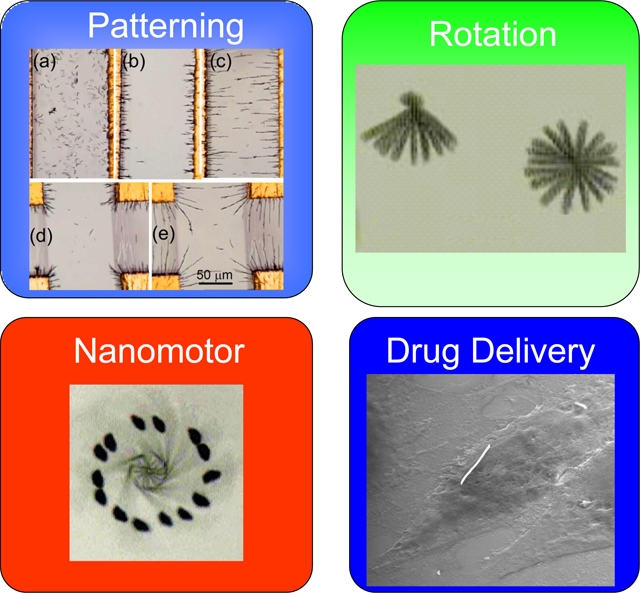
Electric tweezers utilize DC and AC electric fields through voltages applied on patterned electrodes to manipulate nanoentities suspended in a liquid. Nanowires with a large aspect ratio are particularly suitable for use in electric tweezers for patterning, assembling, and manipulation. Despite operating in the regime of extremely small particle Reynolds number (of order 10−5), electric tweezers can manipulate nanowires with high precision to follow any prescribed trajectory, to rotate nanowires with controlled chirality, angular velocity and rotation angle, and to assemble nanowires to fabricate nanoelectromechanical system (NEMS) devices such as nanomotors and nano-oscillators. Electric tweezers have also been used to transport in a highly controlled manner drug-carrying functionalized nanowires for cell-specific drug delivery.
Keywords: Nanowires, nanotubes, manipulation, MEMS, NEMS, drug delivery, nanodevices
Graphical Abstract
Introduction
A wide variety of nanoscale materials with well-defined geometrical shapes have been explored in recent years for their unique and often enhanced properties. These include semiconducting and metallic nanowires [1,2,3,4], carbon nanotubes [5,6,7,8], nanodisks [9], nanospheres [10], and nanorings [11,12,13]. Of particular relevance to the work discussed here are nanowires of high aspect ratios, with diameters ranging from a few tens of nm to of order 0.1μm, composed of either a single phase material or a multisegmented nanowire of two or more materials. While the surface of a nanosphere can only functionalize one kind of molecule, it is possible to accommodate attachment of one (single phase nanowire) or multiple species (multi-segmented nanowire). Extensive work has shown that nanowires can display unique electronic [14,15], optical [16], magnetic [17,18], and mechanical properties [19], owing to, for example, quantum confinement effects or the large surface area to volume ratio. Some of these unique properties have been utilized in devices with enhanced performance, such as nano-lasers [20], optical switches [21], nano-sensors for cellular and molecular diagnosis [22,23], imaging contrast agents [24], and drug/gene delivery vehicles [25], In many instances of scientific or technological interest, the nanowires are removed from the substrates or membranes in which they were synthesized to be freestanding. This results in certain challenges associated with the manipulation and assembly of the freestanding nanowires. Electric tweezers are a newly developed tool that provides for precision manipulation of these nanoentities suspended in a liquid by utilizing DC and AC electric fields through voltages applied on patterned electrodes.
Freestanding small entities are usually suspended in a liquid, such as deionized (DI) water, in order to prevent them becoming too strongly adhered to dry surfaces owing to van der Waals and electrostatic forces that prevent easy manipulation. Small living entities, such as cells and bacteria, can subsist only in a suitable liquid such as a buffered solution. However, once in a liquid, the motion of small entities is in the regime of extremely low Reynolds numbers where large forces are required to move them.
The Reynolds number for a particle moving in a liquid is defined as the dimensionless ratio , where is the density and is the dynamic viscosity of the liquid, and is the size and is the velocity of the particle. is roughly the ratio of the inertial force to the viscous force experienced by the entities. For motion in water, , and therefore the value of . For a typical human swimmer, is of order 105, where the inertial force dominates. In contrast, for a nanowire of diameter moving with a speed of , is of order 10−5, ten orders of magnitude smaller than the human swimmer. For the nanowire, the viscous force dominates the nature of the motion.
One manifestation of a small Reynolds number is the stopping time and distance. This can be quantified in the following way. The motion of a particle of mass suspended in a liquid of viscosity driven by an external force can be described by the equation
| (1) |
where is the acceleration, the velocity, the drag force due to the viscosity , and a coefficient that depends on the size and shape of the entity. The characteristic time of the motion is . For a Au nanowire with a diameter of and length of , this characteristic time . Under a constant , nanowires reach a terminal velocity of within a few sec. When the force is switched off, the moving nanowires will also stop within a few μsec, traversing only a fraction of a nanometer during that time. This behavior is a manifestation of motion in the low Re regime: nearly instantaneous attainment of the steady state velocity as soon as a force is applied and nearly instantaneous cessation of motion after the force is removed.
In the extremely low Re regime, there are few options available for transporting small entities in suspension. One method utilizes a moving liquid to transport the suspended small entities, as is done with microfluidics, which can result in motion in the flow direction. However, it is difficult to deliver the small entities to designated locations26. A different and more challenging scheme is to manipulate the small entities relative to the stationary liquid. There are few forces available for such manipulation. Gravity is one such possibility but is generally too weak to be useful, and even when amplified in a centrifuge, it is restricted to one direction. Applying a force due to a magnetic field is another possibility but is only applicable to ferromagnetic entities [27]. It is also difficult to alter the direction and the magnitude of magnetic fields on small length scales.
In this review, we describe “electric tweezers,” a new and powerful technique for manipulation of nanoentities in suspension by electric fields. Using electric tweezers, nanoentities can be transported to designated locations with controlled orientation, velocity, and along prescribed trajectories with submicron precision. Using strategically designed electric fields, nanoentities can be assembled to form predefined patterns. Electric fields can also rotate nanoentities with controlled angle, chirality, and angular speed in excess of 26,000 rpm.
The high precision and versatility offered by electric tweezers enable various applications from nanoelectromechanical system (NEMS) devices to nano-biotechnology. Electric tweezers have been used to hold, to place, and to assemble individual nanowires into simple NEMS devices, such as nano-oscillators and nano-motors [28, 29]. Recently a single Au nanowire functionalized with a specific drug has been manipulated by electric tweezers to deliver a well defined quantity of drugs to a single mammalian cell surrounded by others that were unaffected [30]. The targeted cell responded to the stimulation from the dose of a single nanowire loaded with only 10−20 mol of drug molecules. All told, electric tweezers, with their ability to provide high precision manipulation of nanoentities in solution, offer great promise in the field of nanodevices, from assembly to operation.
This article will begin with a brief review of the electrochemical synthesis method for the production the nanowires used in our studies of electric tweezers, This will be followed by a detailed analysis of the physics of electrophoretic (EP) and dielectrophoretic (DEP) forces that form the basis of the electric tweezers. Utilization of these forces to pattern, assemble, manipulate, and rotate nanowires, and the application of these processes to NEMS devices and cell-specific drug delivery, will then be discussed.
Fabrication of nanowires
The nanowires we have used in our studies of electric tweezers have been fabricated by electrodeposition through nanopores within a membrane made of polycarbonate [4], mica [31], and other materials. The geometrical size and shape of the nanopores, which range in diameters from 20 to 400 nm with lengths up to the thickness of the membrane from a few to a few tens of μm, determine the dimensions of the nanowires. A Cu layer of 500 nm thickness is first sputtered onto the back of the membrane to seal the pores and to serve as the working electrode in a three-electrode electrodeposition system. The electrodeposition of the nanowires commences at the bottom of the nanopores from the working electrode. The amount of electric charges passing through the circuit controls the length of the nanowires (or of the segments of a multisegmented nanowire) in the membrane. Both single material (e.g., Au) and multisegmented (e.g., AuNiAu-Ag-AuNiAu as shown in Fig. 1) nanowires can be fabricated in this manner. After dissolving the membranes, using 2mol/l NaOH solution in the case of alumina membrane or cloroform in the case polycarbonate membrane, the nanowires become freestanding and can be sonicated and centrifuged in ethanol and deionized (DI) water twice before resuspended in DI water.
Figure 1.
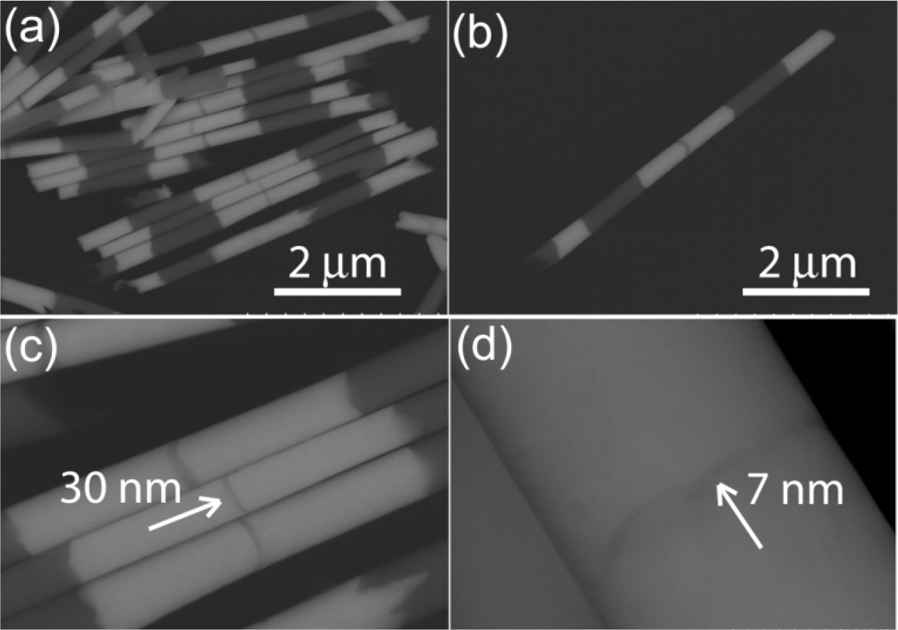
Both single and multi-segmented nanowires can be electrodeposited into nanoporous templates. For instance, (a)(b) Multi-segment AuNiAu-Ag-AuNiAu nanowires have been electrodeposited. The diameters, controlled by the pore sizes, range from 20– 400 nm. (c)(d) The lengths of each segment, determined by the amount of charges passing through the circuit, can be tuned from 7 nm to a few micrometers.
Electric Tweezers
Ordinary tweezers are a mechanical tool that can physically hold a small object and move it from one location to another by hand. However, holding a very small object, such as a nanowire, via a mechanical device is not feasible. Optical tweezers [32] and magnetic tweezers[33,34,35] have been invented in recent years to “hold” certain nanoentities. In the former, a focused laser beam holds a dielectric particle in the “waist” of the beam profile, while in the latter a magnetic field gradient holds a paramagnetic particle. An entity of interest (e.g., DNA) can be attached to a dielectric particle or a paramagnetic particle, thus be indirectly held in place by respectively the optical or the magnetic tweezers [36,37]. Since optical and magnetic tweezers hold the particle by trapping it in the field, there is no net force delivered to the particle to move it. Instead, a particle is “moved” by mechanically moving the stage. It would be far more versatile if one could “hold” and apply a force to manipulate small entities in suspension and, even better, perform it with no moving parts. Electric tweezers can accomplish this feat.
Electric tweezers enjoy certain distinct advantages compared to either the magnetic or the optical counterpart. By suitable functionalization, a small entity in suspension can be made to carry either positive or negative charge to be responsive to a DC electric field. For electrically neutral entities, one can use AC electric field to induce an effective electric dipole moment and manipulate them with the electric field gradients (EFG). Unlike optical and magnetic tweezers, which require extensive instrumentation, electric tweezers use a relatively simple approach in which voltages are applied to strategically designed electrodes that can produce the necessary DC and AC electric fields. Finally, there are no mechanically moving parts in electric tweezers except for the small entities being manipulated.
Physics of Electrophoretic (EP) and Dielectrophoretic (DEP) forces
When an electrically charged particle is suspended in water, an electric double-layer (EDL) is formed proximal to the surface of the particle. The electric charge on the particle is partially screened by the EDL, resulting in an effective electric potential at the interface between the particle and the liquid medium. In a DC field, the charged particle moves in the field due to the Coulomb force. This is the electropheretic (EP) force, and at steady state it is balanced by the viscous force, leading to a terminal velocity of [38]:
| (2) |
where and are the permittivity and viscosity of the liquid, respectively, and is the permittivity of free space.
The dielectrophoretic (DEP) force is the force that an electrically neutral particle experiences in an electric field owing to the interaction between the field and the polarization of the particle [39]. Most DEP phenomena are realized in electric fields at high frequency to circumvent the screening effect of the water whose large dielectric constant of 80 reduces the DEP force by 6400 times. It is the induced electric dipole moment on the particle (charged or otherwise) that experiences the DEP force[40], which is the force on the induced dipole moment that results from the electric field gradient :
| (3) |
where is the effective induced dipole moment of the particle in the field, is the volume of the particle, is the dielectric constant of the medium, and is the real part of the Clausius-Mossotti factor . The Clausius-Mossotti factor
| (4) |
is dictated by the frequency dependent dielectric constants of the particles and of the medium , the geometrical shape of the particle, and the relative orientation of the particle to the electric field, where is the depolarization factor[41].
Nanoparticles with a large aspect ratio, such as nanowires, are particularly advantageous for manipulation by the DEP force [42,43]. Our calculations show that the electrical polarization of a metallic nanowire of diameter and length , is enhanced 380 times over that of a metallic sphere with the same diameter. If we approximate nanowires as prolate spheroids, we find a large difference between for the field parallel to the nanowire and for field perpendicular to the nanowire. As a result, the Clausius-Mossotti factor, and thus the DEP force, depends sensitively on the orientation of the nanowire orientation with respect to the field. It should be noted that the Clausius-Mossotti factor depends on the electrical characteristics of both the particles and those of the medium. In particular, the low conductivity of the DI water substantially enhances the DEP effect.
Characterization of DEP force
To experimentally verify the theoretical predictions of the DEP forces we manipulated Au nanowires immersed in DI water [44] that were placed within concentric circular electrodes consisting of an inner and an outer electrode with radii of and , respectively, as shown in Fig.2(a). The advantage of the concentric circular electrode configuration is that the field, the , and resultant force are all directed along the radial direction with the simple dependences of , and respectively, where is the distance from the center of the inner electrode. From Eq. (2), we obtain the following analytical expression for the magnitude of the DEP force:
| (5) |
where is the root mean square of voltage, is the volume of the nanowire, and are the radii of inner of outer electrodes respectively, and is the permeability of the medium. From Eq. (5) the value of the DEP force in circular electrodes is expected to vary as .
Figure 2.
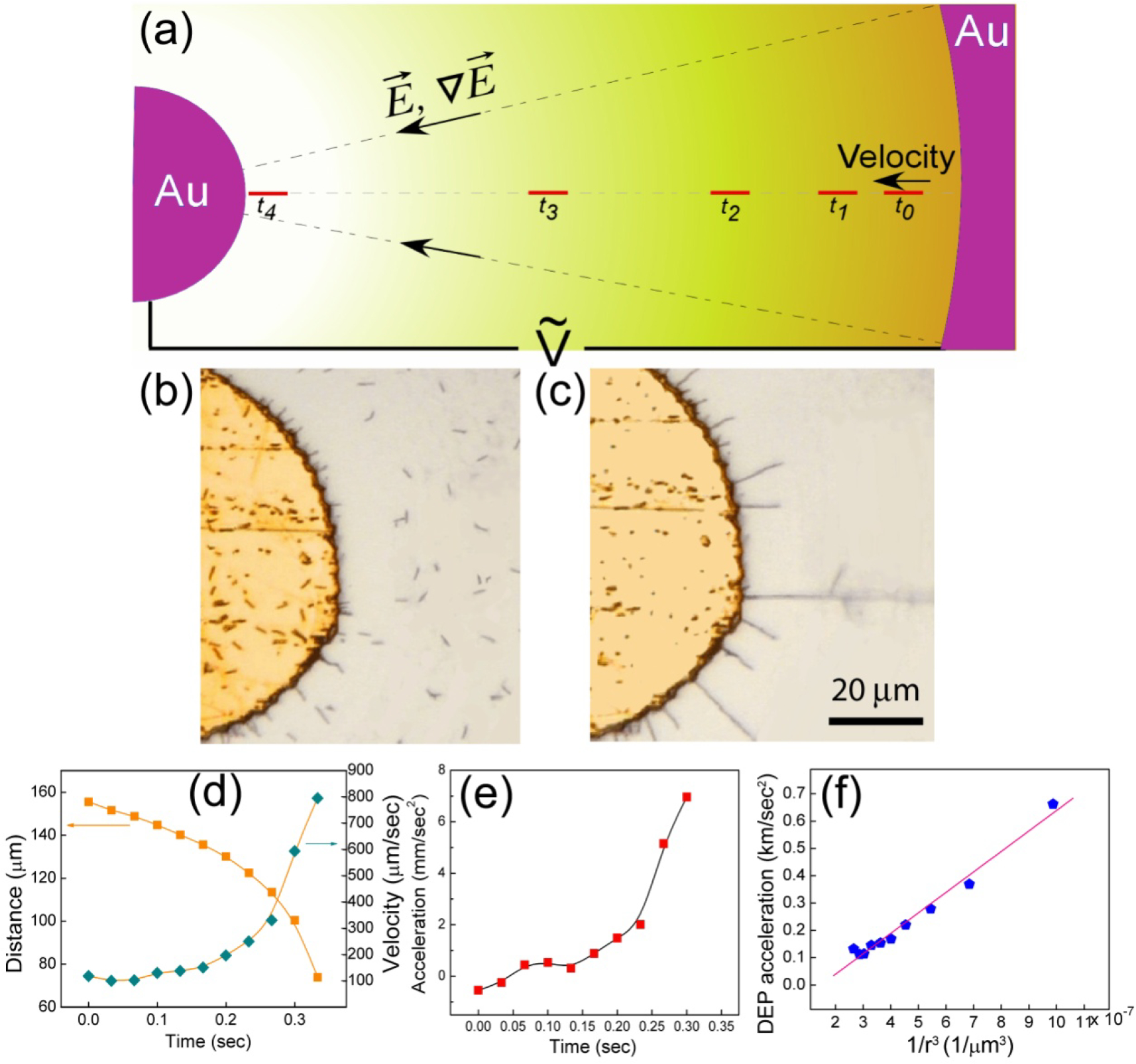
(a) Schematic diagram showing the transport of nanowires in a circular electrode by DEP force. (b) The randomly dispersed nanowires (c) can be transported and aligned radially unpon application of 8V, 50 MHz on the circular microelectrodes. (d) Plotting the transport distance to the center of the circular electrode as function of time (orange squares) and do the first derivative and second derivative, the velocity (blue diamonds) and (e) the acceleration (red squares) can be readily obtained as function of time. (f) As a result, the acceleration of the nanowires due to DEP force is calculated, which is linearly proportional to 1/r3.
We suspended the Au nanowires in the gap of the circular electrodes as shown in Fig. 2(b). After the field has been applied, all the suspended nanowires immediately aligned radially, accelerated towards the center, and finally attached to the inner electrode [Fig. 2(c)]. We captured the motion of about 1 second with a CCD camera with 30 frames/sec and plotted the position of the nanowire from the center as a function of time as shown in Fig. 2(d), from which the velocity () and acceleration of nanowires can be obtained by taking the first and second derivative with respect to time. As shown in Fig. 2(d), the velocity of nanowires increases rapidly and monotonically, reaching a speed of , which is extremely high for small objects in suspension. In comparison, E-coli, with a similar shape and size as those of nanowires, can move with a speed of only . A very high acceleration of has also been achieved as shown in Fig. 2(e).
Substituting the experimentally measured values of the acceleration and velocity into Eq. (1), the DEP force of can be determined. As shown in Fig. 2(f), the acceleration from the DEP force indeed varied as in agreement with Eq. (5). Most notably, as shown in Fig. 2(f), the value was extremely large, as high as 0.7 km/sec2, or 70 times the acceleration due to gravitaty, demonstrating how large a DEP force can be produced. However, the large viscous force, as manifested by the low Reynolds number of 10−5, results in a reduction of the net force by five orders of magnitude.
For the circular electrodes, the electric field and its gradient are in the same direction. In order to separate the different effects of the field and , we designed a quadrupole electrode system that could produce an perpendicular to the field. As shown in Fig. 3(a), electrodes on the opposite sides of the quadrupole electrode were electrically connected and between them an AC voltage of at was applied. The calculated field (shown by the lines) and the equipotential curves (shown by the color contours) are shown in Fig. 3(a). Note that the field gradient is perpendicular to the field and directed away from the center towards the gaps of the electrodes.
Figure 3.
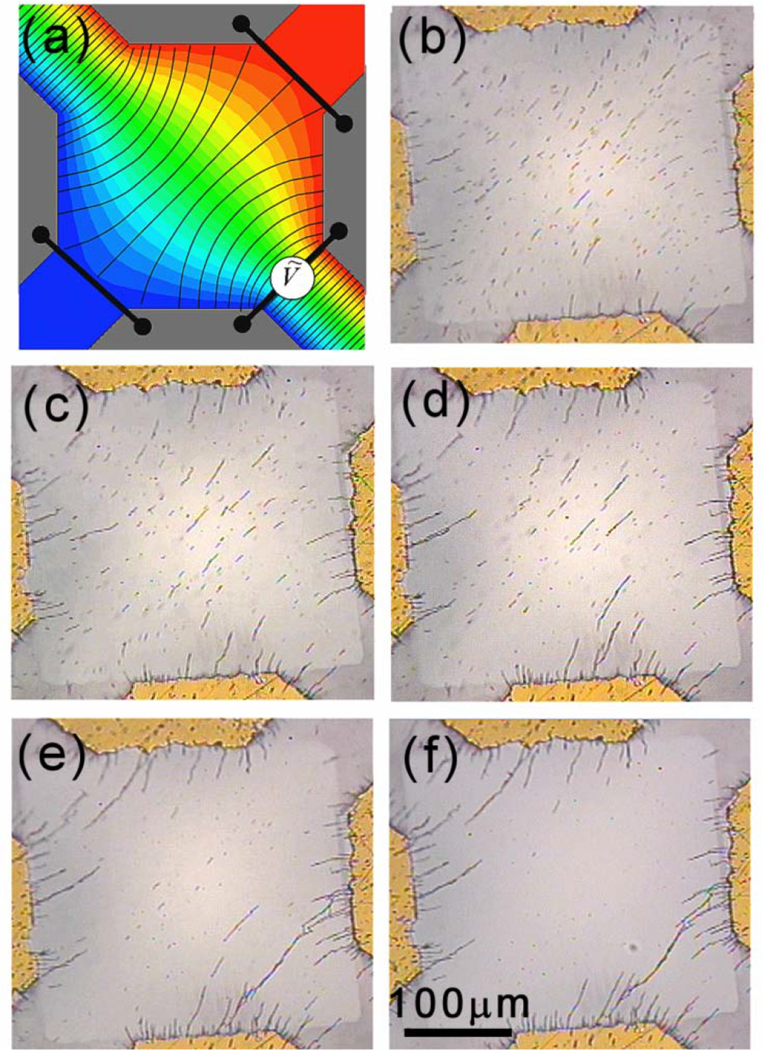
(a) Potential (in color contour) and E field (in black lines) distribution in a quadrupole electrode with connected pairs of electrodes. Images of nanowires in suspension at (b) 2 sec, (c) 6 sec, (d) 10 sec, (e) 59 sec, and (f) 180 sec after an AC field of 10V at 1 MHz applied.
Au nanowires were randomly dispersed in the center of the electrodes (Fig. 3b) and the motion of these nanowires were recorded after the application of the AC potential As shown in Fig. 3b, 3c, 3d, 3e and 3f taken at 2, 6, 10, and 59 sec, respectively, after the application of the voltage, alignment of the nanowires along the E field effectively occurred instantly (Fig. 3b), followed by nanowire chaining (Fig. 3c), and transport into the high-field regions, the nanowires being aligned perpendicular to the direction of motion (Fig. 3d–f). As a result, the nanowires were depleted from the center (Fig. 3f). The alignment and the assembly of nanowires clearly demonstrated the different roles of the electric field and its gradient. The alignment of the nanowires was associated with the direction of the E field while the direction and velocity of the motion was a result of EFG. By strategically designing the microelectrodes and applying the potential, there is freedom to configure both the E field and EFG in various ways to achieve transport of the nanowires with different orientations. When the AC voltage was turned off, the motion of all of the nanowires effectively ceased (reflecting the sub-nanometer stopping distance), a very desirable and often critical feature when assembling nanowires into devices.
Patterning
Due to the distinct effects of E field and EFG in aligning and transporting nanowires, the DEP force can be used for assembling nanowires in suspension into various scaffolds efficiently. We found that the assembling efficiency strongly depends on the applied AC voltage and the frequency, and the assembling morphology is affected by the AC frequencies [45].
We now describe patterning using two microelectrodes to illustrate the process. The “cross” electrodes shown in Fig. 4 demonstrate the distinctive effects of the E field and the EFG, whereas the “dipole” electrodes shown in Fig. 5 demonstrate how non-linear scaffolds can be achieved using DEP. In each case, we have calculated in two-dimensions the E field, the equipotential curves, and the EFG in the gap regions.
Figure 4.
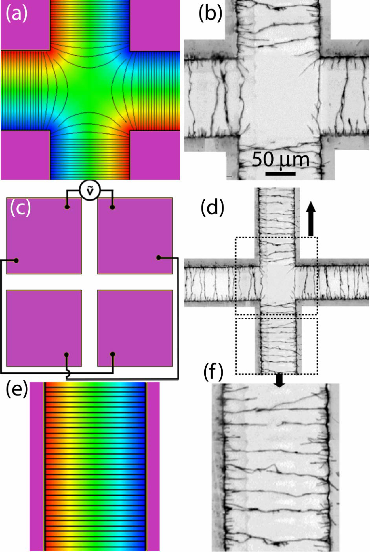
(a) A “cross” gap defined by four rectangular electrodes. (c) The diagonal pairs of electrodes are electrically connected and between the pairs an AC voltages is applied. Calculated electric field lines and equipotential contours in color are shown in (a) for the central region and (e) away from the central region. The actual assemblies of nanowires under VAC = 5 V and f = 1 MHz are shown in (d) with the enclosed areas enlarged in (b) and (f).
Figure 5.
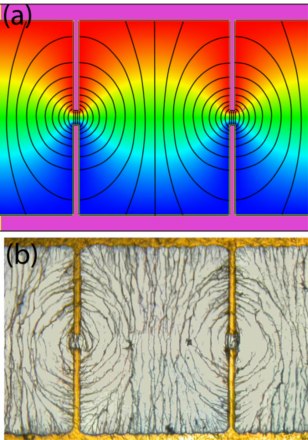
(a) The electric field lines of the “dipole” electrodes with a gap of 30 μm and (b) the corresponding nanowire assembly.
The “cross” electrode consists of four rectangular electrodes resulting in four relatively long gaps and a central square region of 125 μm × 131 μm (Fig. 4c). The diagonal pairs of electrodes were electrically connected, and between them an AC voltage of VAC = 5 V at a frequency of f = 1 MHz was applied. The calculated E field (represented by the E field lines) and the equipotential curves (the color contours) showed that the E field was approximately uniform and perpendicular to the edges of the electrodes in the long gaps (Fig. 4e). In the central square region, the E field lines were approximately square near the edges but become progressively distorted as the center was approached (Fig. 4a). In the area far away from the center, the E field lines were nearly equally spaced with nearly zero EFG. The E field in the central square region was distinctly non-uniform, where the directions of EFG were mainly along the long gaps directed away from the center.
After the application of the AC field, all the nanowires in the long gaps were aligned with the local E field as shown in Fig. 4f. As can be seen, the nanowires were perpendicular to the edges of the electrodes, chained and bundled into longer wires, and some had bridged the gap between the electrodes in chains consisting of as many as 50 Au nanowires.
In the central square gap of the “cross” (Fig. 4b), however, there were essentially no Au nanowires left. The Au nanowires originally in the center region had been driven away by the local EFG along the EFG direction, which in this case was perpendicular to the E field direction. The “cross” electrode thus illustrated the assembly of nanowires by an AC E field both with (in the central square gap) and without (in the long gaps) an EFG. This process of assembling nanowires into a scaffold was rather efficient, completed within 1.6 sec at 10 V.
The second example was the “dipole” electrode, consisting of two long tips of width 15 μm separated by a small gap of 30 μm as shown in Fig. 5a. In this case, the E field was highly non-uniform with a substantial EFG in the vicinity of the gap. The E field lines near the gap were quasi-elliptical in shape and resembled that of an electric dipole. The Au nanowires in DI water placed over the gap rapidly formed a pattern within 8 sec after an AC voltage of 10V at 50 MHz was applied (Fig. 5b). The final scaffold closely followed the calculated E field lines with substantial amounts of chaining.
One can create desirable scaffolds by generating the necessary E field distributions from suitably designed electrodes with the proviso that there are never any crossed nanowires since E field lines can never cross each other. However, one can assemble in stages with different layers such that the nanowire scaffolds can be assembled with each layer having a different pattern.
It should be mentioned that the assemblies shown in Fig. 2c, 3f, 4d, and 5b remained unchanged even after the AC E field was turned off. This was owing to the effects of the extremely small Reynolds number, which resulted in the termination of all motions (except Brownian motion) in the absence of external forces. After the solution had evaporated, the nanowire scaffolds remained essentially intact and attached to the substrate surface by van der Waals forces. In this manner, a scaffold assembled from nanowires can be maintained outside of the solution.
Summarizing this section, we have shown how assemblies and scaffolds of nanowires in suspension can be produced with electric tweezers using strategically designed electrodes and AC electric fields. The orientation of the nanowire assemblies closely follows the electric field lines generated by the electrodes. The assembling efficiency and the morphology strongly depend on the applied AC voltage and frequency.
Rotation
We mentioned above that the DEP force can align the nanowires in the direction of the E field. This suggests that a method of rotating nanowires can be accomplished by creating a rotating E field in the middle of a set of quadruple electrodes. We investigated this process using such an electrode configuration with a gap of about 300 μm and by applying four AC voltages with sequential 900 phase shifts [Fig. 6(a)] [28]. These voltages caused nanowires that were placed in the central region between the four electrodes to rotate as shown by the snap shots taken every 0.33 sec. The Au nanowires were 50 nm in diameter and 5 μm in length, and the applied AC potential was 5 V at 20 kHz [Fig. 6(b)]. The rotation angle was recorded by analyzing a video taken of the rotation frame by frame. The rotation angle varied linearly with time [Fig. 6(c)] with a constant angular velocity ω. This was the expected terminal velocity, and its nearly instant attainment was a manifestation of the extremely low Reynolds number. The chirality of the rotation could be dictated by the phase shift of the voltages. The nanowires acquired the terminal angular velocity of opposite chirality instantly with no apparent acceleration or deceleration, and the rotation instantly stopped when the voltages were removed [Fig. 6(c)]. The angular velocity depended on both the magnitude and the frequency of the applied AC voltage. At a fixed frequency, the rotation rate increased as V2 as shown in Fig. 6(d). For Au nanowires, the rotation rate increased with frequency from 5 kHz to 100 kHz before gradually decreasing to much smaller values near 1 MHz, as shown Fig. 6(e).
Figure 6.
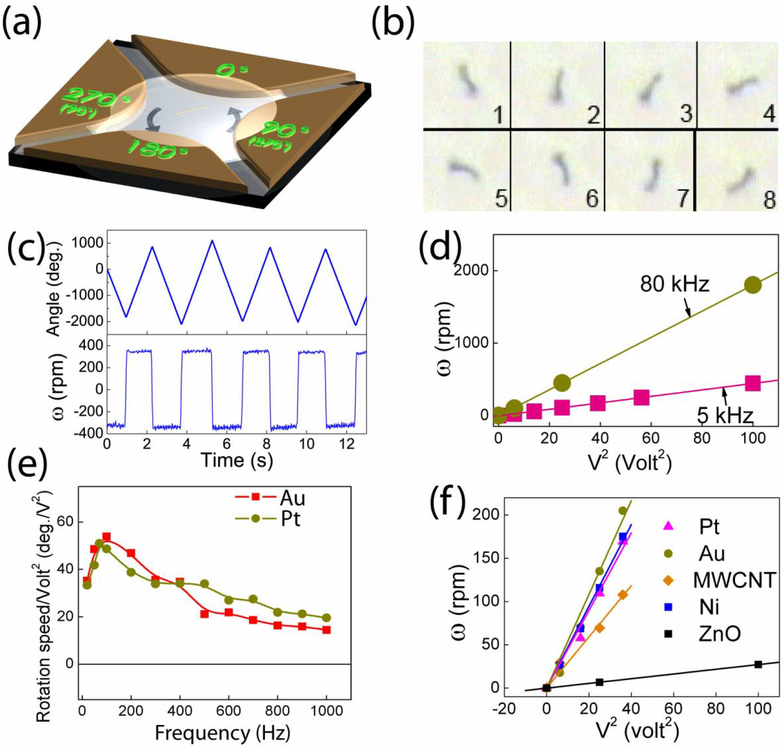
(a) Schematics of rotation of nanowires in suspension by AC voltages applied on the four parts with 900 phase shifts of a quadrupole electrode. (b) Overlapped images at 1/30 sec interval of free rotating Au nanowires (50 nm in diameter, 10 μm in length) at 5V, 20 kHz. (c) Angle and speed of rotation of Au nanowires at 4, 0, 6, 0, and −8 V. The start and stop of the rotation of the nanowires is instantaneous without apparent acceleration or deceleration. (d) Rotation speed of free Au nanowires at 5 and 80 kHz as a function of V 2. (e) Rotation speed normalized by V2 versus AC frequency at for free Au and Pt nanowires. (f) Rotation speed of Au, Ni, Pt nanowires (10 μm in length, 0.15 μm in radius), ZnO nanowires (5 μm in length, 0.2 μm in radius), and multiwall carbon nanotubes (5 μm in length, 10 nm in radius) versus V2.
The rotation of nanowires can be understood as a result of the interaction between the AC E field and the induced electric dipole moment p, whose value depends on the material and the geometrical shape of the entities, and is proportional to the E field. Under an AC electric field, the nanowire experiences a torque of Te= p x E, which varies as E2. This torque is balanced by the viscous torque, which is proportional to the viscosity η and the angular velocity ω. Consequently, ω is proportional to E2, which accounts for the V2 dependence observed experimentally.
The V2 dependence is advantageous for achieving high angular speed. Using a camera capable of taking 30 frames/s, we have observed the rotation of Au nanowires (10 μm in length, 0.3 μm in diameter) at 10V, with f = 80 kHz in a quadruple electrode of size 150 μm, to a speed of 1800 rpm, beyond which our video system could not accurately track the rotation. To explore higher rotation speed, we switched to a high speed CCD camera operating at 2000 frames/sec. We explored different nanowires (Au, Ni, Pt) with various aspect ratios (6.7 to 33), and AC frequencies (5 kHz to 1 MHz). We found that Au nanowires with aspect ratios of about 16 subjected to an AC E field of frequency 80–100 kHz achieved the highest rotation rates as shown in Fig. 6(e). We have achieved for Au nanowires at 20V with f =100 kHz in a quadruple electrode of size 100 μm an angular velocity of 26,000 rpm, which is perhaps a record but surely not the limit.
In addition to Au nanowires, we have also rotated other metallic nanowires (Pt), magnetic nanowires (Ni), multiwall carbon nanotubes (MWCNT), and insulating (ZnO) nanowires, all showing the V2 dependence of the angular frequency ω [Fig. 6(f)]. At the same voltage, the angular velocity appears to scale with the conductivity of the nanoentities, as shown in Fig. 6(f), with Au rotating the fastest and ZnO the slowest at the same voltage.
We have thus demonstrated a method of using rotating electric field to rotate nanowires with complete and sensitive control of rotation chirality, rotation velocity, and rotation angle. A rotation velocity of at least 26,000 rpm has been observed. Rotating nanowires can be exploited for NEMS devices, such as nanomotors, nano-oscillators, and and nanostirrers.
Electric tweezers
As described above, the DEP force can efficiently transport and rotate nanowires due to the interaction between the polarized nanoentities and the AC electric field. However, the DEP force alone is still inadequate for electric tweezers. The main deficiency of the DEP force is the lack of reciprocity. In the first example of concentric circular electrodes, one notes that the DEP force can transport the nanowires inward but not outward. This is because, as shown in Eq.(3), the DEP force is proportional to ∇E2, which is towards the larger value of the absolute value of E. The unidirectional transport is inadequate for truly versatile tweezers, which must be able to transport small entities along arbitrary directions and to arbitrary locations. We describe below the newly developed technique of electric tweezers that can independently control the transport and the alignment of nanowires, and can manipulate the nanowires to follow any trajectory in two dimensions.
The electrical tweezers technique is based on the simultaneous application of uniform DC and AC electric fields on charged nanowires. In a uniform DC electric field E, a nanowire carrying a charge q experiences an electrophoretic (EP) force of qE and reaches a constant terminal velocity v as given by Eq.(2). The charge q on the nanowires, both sign and magnitude, can be altered by chemical functionalization. Under a uniform AC field, as shown by Eq. (3), there is no DEP force to cause motion of the nanowires, but there is a torque of p x E that aligns the nanowires. In short, the electric tweezers use a uniform AC field to align the nanowires and a uniform DC field to transport nanowires to achieve a complete control of the manipulation [29].
Applications of Electric Tweezers
Precision manipulation
We patterned by optical lithography two sets of parallel electrodes on quartz substrates for providing uniform electric fields in the X and Y directions to independently control the motion in these two directions. The Au nanowires can be made to be either postively or negatively charged by suitable functionalization. We modified the surfaces of Au nanowires by thiol conjugation using molecules with a thiol group (−SH) attached to the Au surfaces at one end with either a carboxyl group (−COOH) or an amino group (−NH2) at the other end. After suspension in DI water, the carboxyl group ionized into - COO− and the amino group ionized into - NH3+, causing the nanowires to be negatively and positively charged respectively. We placed the charged nanowires in suspension in the center region of the quadruple electrodes, waited 20 second for them to settle before applying voltages to the electrodes using AC voltages (2–8 V, 10–50 MHz) and DC voltages (1–2.5 V). When the AC field is applied parallel [Fig. 7(a)] or perpendicular [Fig. 7(b)] to the DC electric field, we have achieved nanowires with orientation parallel or perpendicular respectively to the direction of the motion as shown in Figs. 7(d) and 7(e). When no AC field is applied [Fig. 7(c)], the nanowires are randomly oriented during motion [Fig. 7(f)]. The transport velocity is linearly proportional to the DC voltages as shown in Fig. 7(g) and (h) as expected from Eq. (1). However, different speeds were observed for the parallel (solid red squares) and the perpendicular (hollow blue diamonds) orientation, a reflection of the different viscous forces for the two orientations as shown in Fig.7(h) for Au nanowires of 300 nm in diameter[29]. The difference in speeds are smaller for MWCNTs transported parallel or perpendicular to their orientations Fig.7(g).
Figure 7.
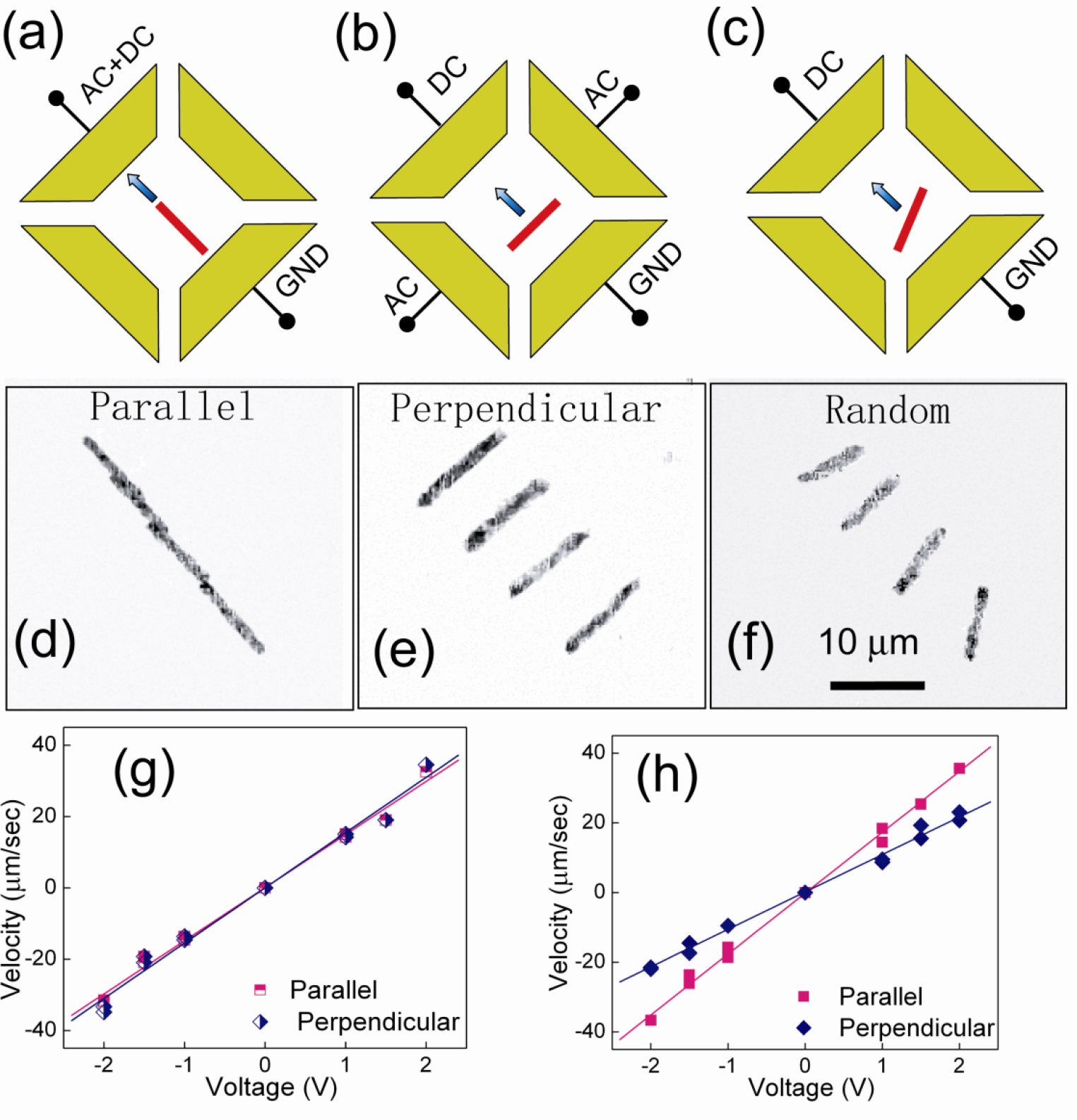
Schematics of voltage configurations with the DC field (a) parallel and (b) perpendicular to the AC field and (c) without the AC field. Overlapped images of MWCNTs of 5 μm with orientations (d) parallel (Δt=0.40 s), (e) perpendicular (Δt=0.20 s), and (f) random (Δt=0.40 s) to the transport directions. (g) The transport velocities linearly depend on dc voltages for both parallel and perpendicular transports. (h) The nanowires align with the external ac E field in 1 sec. The inset shows that the deviation of the alignment of the nanowires from the ac E field is approximately 5 degrees for nanowires transported parallel with their alignment, and 10 degrees for nanowires transported perpendicular to their alignment. The deviation angle also increases with the transport speed which is proportional to the DC votages.
Examples of two-dimensional manipulation of nanowires with parallel orientation executing a zigzag path and a square path are shown in Fig. 8(a) and 8(b) respectively. After each 900 turn, the nanowires quickly aligned themselves into the direction of the motoin within 1 s as shown in Fig. 8(c). In these examples, the nanowires were manipulated from their initial locations to the end locations and brought back to their initial locations following the same paths, either zigzag or square. The nanowires can be brought back within a few μm from the starting locations after traversing hundreds of micrometers. This attests to the precision of the manipulation, limited largely by the Brownian motion of the nanowires.
Figure 8.
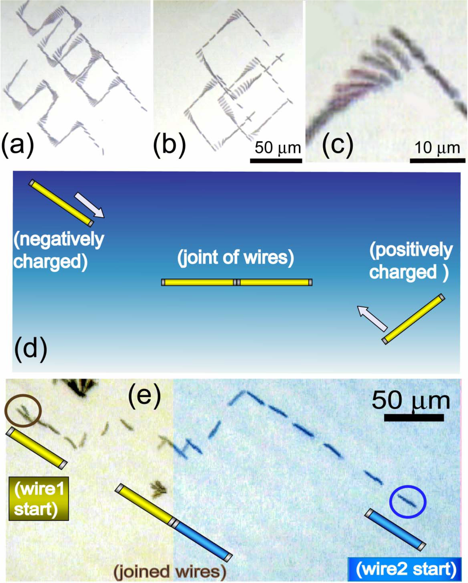
(a) Nanowires can be manipulated along arbitrary trajectories such as zigzags and (b) squares as shown in the overlapped images. (c) They were quickly turned and aligned in the transport direction when the E field is switched from X to Y direction. (d) By using this technique, two oppositely charged nanowires can be connected tip to tip. As shown in (e) two oppositely charge nanowires were transported in both X and Y directions, they were aligned in the same direction, transported towards each other, and joined tip to tip. This attests the precision is at least 150 nm, the radius of the nanowires.
In these examples, the trajectory consists of a series of linear segments in the X and Y directions. Since the linear segments can be made arbitratily small, the nanowire can be compelled to follow any prescribed curve trajectory between any two points.
Joining of nanowires
Unavailable to either magnetic or optical tweezers, manipulation by electric tweezers can exploit different types and amounts of electric charges on the nanowires. As mentioned earlier, using carboxyl and amino chemistry, we can place opposite charges on the Au nanowires, which moved in opposite directions under the same DC E field Fig. 8(c). By manually controlling the sequence of voltages supplied to the electrodes, the two oppositely charged 6-μm long Au nanowires with diameter of 0.3 μm, initially separated by 185 μm, can be moved towards each other and eventually connected tip to tip, as shown in Fig. 8(d). This experiment demonstrates the sub-μm precision of electric tweezers, unmatched by other manipulation methods. The opposite charges on the two nanowires are not equal. One can estimate from the length of the trajectory shown in Fig. 8(d) that the charge ratio is about 1:2. Calculation using Eq.(2) shows that the positively and the negatively charged nanowires have zeta potentials of 13.3 mV and - 21.8 mV respectively, giving a ratio of about 1:1.6.
After the E field has been turned off, the two joined Au nanowires tend to separate, probably due to Brownian motion. However, the joint can be better secured by using short Ni segments 1 μm at the two ends as in Ni-Au-Ni multisegmented nanowires. Due to the magnetic attraction between the Ni ends, the joined nanowires remain intact as schematically shown in Fig. 8(e). We will exploit this scheme in the assembling of NEMS devices from nanowires.
MEMS/NEMS devices
Electric tweezers can manipulate, assemble, and deliver a large force, and thus can be exploited for MEMS/NEMS devices. Here we mention two examples of nanowire oscillators and nanowire motors.
— Nanowire oscillators
The same manipulation method of joining two oppositely charged nanowires can assemble simple NEMS devices. A “V” shaped device was formed by joining two oppositely charged Ni-Au-Ni nanowires end-to-end while the other two ends were pinned to the quartz substrate by non-covalent bonds between Ni and quartz. This simple “V” shaped device with two anchoring points on the substrate can be driven into mechanical oscillations by AC square-wave voltages (1~ 2.5V) as schematically shown in Fig. 9(a). The orientation of the oscillator, as characterized by the angle of oscillation between the plane of the oscillator and the normal direction of the substrate surface, were measured from the projection length of the structure as shown in Fig. 9(b), which reveals the mechanical oscillation with frequencies from 0.5 to 2.5 Hz [Fig. 9(c)], the same as that of the AC driving voltages. The oscillator operating in water, thus relevant to biomedical applications, has been entirely assembled in situ from individual nanowires using EP and DEP manipulation.
Figure 9.

(a) Schematics of a nanowire oscillator assembled in D.I. water by joining two oppositely charged Au nanowires (6 μm), the joint secured by the magnetic Ni segments at the ends. (b) Top view images of the nanowire oscillator as it oscillates between 90° and −90°, the angle between the plane of the oscillator and the normal direction of the quartz substrate. The last picture shows the overlapped images. (c) The oscillation angle as a function of time showing the oscillation frequencies are same as that of the square wave E field at 1 kHz (blue line) and 2 kHz (pink line). We have controlled the frequency of the nano-oscillator from 0.5 to 2.5 Hz.
The rapid assembling of this simple NEMS device in suspension can be extended in sequence or in parallel to accommodate more complex arrays of devices as well as attaching chemical, biological, or other functionalities.
— Nanowire motors
We have earlier shown rotation of nanowire by a rotating E field. We have further constructed a nanowire motor consisting of a bent nanowire as the “rotor,” the chemical connection between the kink of the nanowire and the quartz substrate as the “bearing,” the quadruple electrodes as the “stator,” and set it into rotation with a rotating AC voltage of 10V at 20 kHz [Fig. 10(a)]. A dust particle in the path of the rotor has been occasionally driven into motion by the bent nanowire as shown in the overlapped snap shots in Fig. 10(b). However, the dust particle maintains a circular trajectory always in the path of the rotating nanowire despite repeat strikes by the nanowire as shown in Fig. 10(c). This is because in the low Reynolds number regime, the dust particle moves only upon impact, and the dust particle stops as soon as contact with the nanowire ceases. One notes this nanowire motor is one of the smallest electrically driven motors with chemical bearings. Its relevance to micromotors, microfluidic devices, microstirrer, etc. is apparent.
Figure 10.
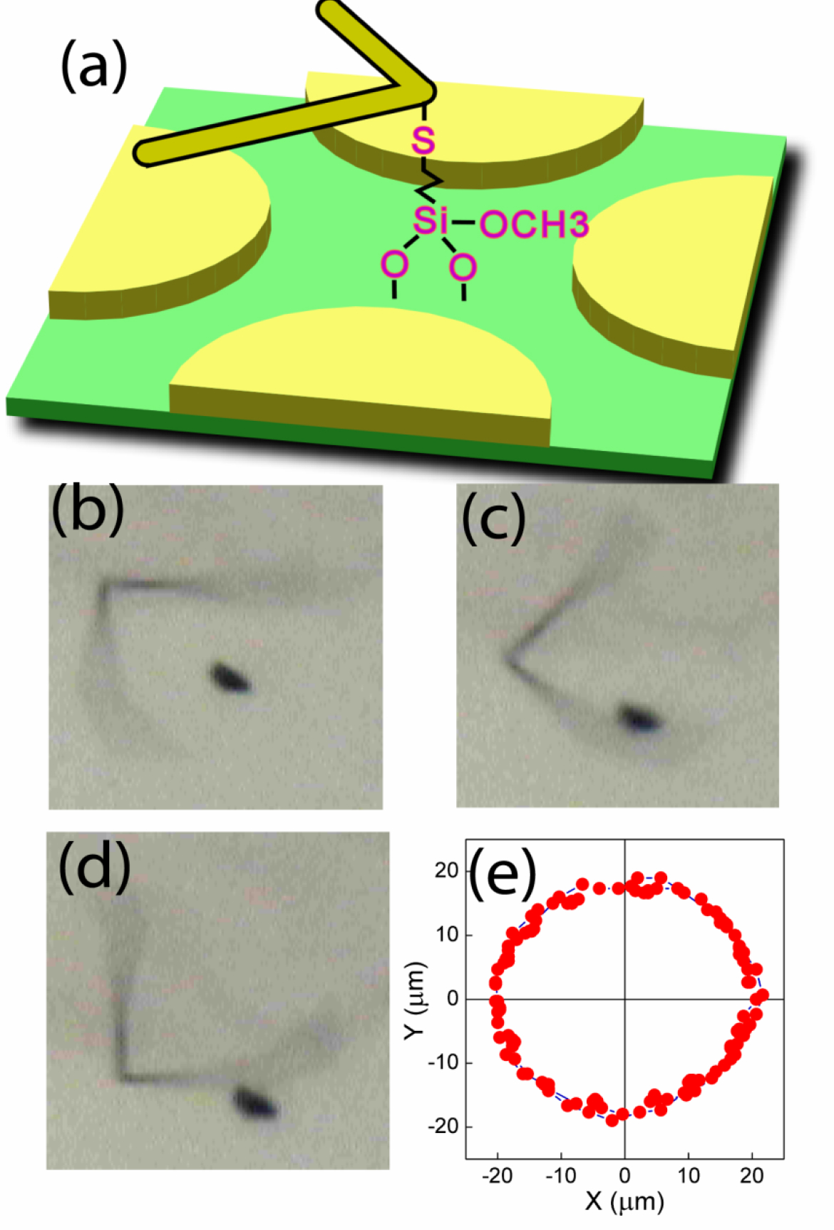
(a) A nanowire rotor with a bent nanowire as the rotor, the chemical connection between the kink of the nanowire and the quartz substrate as the bearing, and the quadruple electrodes as the stators. This nanowire rotor has driven a dust particle into rotary motion as shown in both the snap shots (b) and the trajectory of the dust particle every 0.33 sec.
Nano-biotechnology — Cell-specific drug delivery via nanowire vehicles manipulated by electric tweezers
Electric tweezers command complete control of the manipulation of nanowires. Nanowires can be functionalized to carry specific charge, chemicals, and drugs. Combining these two capabilities, one can direct nanowires with payload via electric tweezers to strategic locations. We have exploited these aspects in nano-biotechnology, specifically, cell-specific drug delivery [30]. The drug can be readily administered to all the cells in the container. Electric tweezers enables drug delivery to one specific cell in the midst of many. We first conjugated Au nanowires with tumor necrosis factor-alpha (TNF-α) by hydrophobic absorption. We then precisely transported a drug-conjugated nanowire using electric tweezers as schematically shown in Fig. 11(a). The actual delivery is shown in Fig. 11(b), where one drug carrying nanowire has been manipulated onto the membrane of one specific mammalian cell for stimulation of cellular responses37. We have observed the response of the targeted cell in the midst of many unaffected cells. We found that one TNF-α conjugated nanowire is sufficient to stimulate the cell as revealed by the translocation of nuclear factor-kappa B (NF-κB) from cytoplasm to the nucleus. We have also shown that multiple nanowires can be delivered sequentially to a single cell as shown in Fig.11 (d) and (2). As a result, we can precisely control the amount of drugs delivered to a biological cell. This method is useful for studies of cell signaling, gene, and drug delivery, on the single-cell level.
Figure 11.
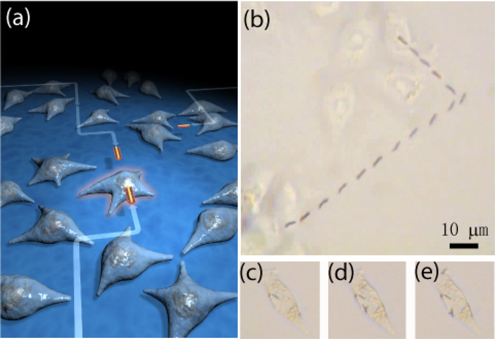
(a) (b) The nanowires can be precisely transported onto a selected cell following any prescribed trajectory using electric tweezers. (c)-(e) Multiple nanowires can be delivered to a single cell one by one.
The above example of cell-specific delivery of one drug uses Au nanowires. Multiple drugs can be functionalized on the surface of different segments on a single multisegmented nanowire for multi-drug delivery to a single cell. One can study how multiple drugs synergistically stimulate one cell amidst many, and how the stimulated cell communicates with its surrounding cells. One can also deliver a number of nanowires carrying different drugs sequentially to an individual cell at different times to understand cell signal transduction with unprecedented control. There are a wide range of opportunities in biology and biomedical engineering that await site-specific stimulation by chemicals and drugs enabled by electric tweezers to be carried out in vitro and perhaps one day in vivo settings. Therefore we anticipate that this technique will find wide application in the fields of cell biology and bioengineering, and will affect how biologically active compounds are delivered to cells and cell groups in various in vitro and in vivo settings.
Summary and prospective
The “electric tweezers” technique is based on AC and DC electric voltages applied on micro-electrodes for precision manipulation of nanoentities including transport, patterning, and rotation. The electric tweezers is enabled by the DEP torque and the EP force. The DEP force is due to the interaction between the polarized nanoparticles and the AC electric field gradient. In a uniform AC field, there is no electric field gradient but only the DEP torque, which aligns but does not transport the nanowires. The actual transport of nanowires is accomplished by the EP force, which is the Coulumb force on electric charges on the surface of the nanoparticles by the DC electric field. The nature of these forces has been quantitatively verified. Exploiting the different nature of these two forces, we strategically designed microelectrodes to capitalize on both the DEP and EP forces in electric tweezers. We showed that the electric tweezers can transport nanowires along arbitrary trajectories with their orientations parallel or perpendicular to the transport direction. Despite a large initial separation, the electric tweezers can join two oppositely charge two nanowires. Using rotating AC electric field, the electric tweezers can completely control the rotation of nanowires, their angular speed up to at least 26,000 rpm, rotation chirality, and even the total angle of rotation. The versatility of the electric tweezers has been demonstrated in several examples ranging from assembling and operating NEMS device to cell-specific drug delivery. The combination of precision of the manipulation of the electric tweezers and the multifunctionalities of the nanowires are unmatched by other techniques. The implementations of electric tweezers in other fields will only be expanded.
*Research Highlights.
We review the use of electric tweezers as a method of manipulating nanowires in suspension.
We discuss the physical principles associated with electric tweezers.
We give examples of nanoscale devices that can be produced.
We show how electric tweezers can be used for subcellular drug delivery.
Acknowledgments
Work supported in part by U.S. National Science Foundation grant DMR05–20491. DLF gratefully acknowledge startup package from Cockrell School of Engineering and Research Grant from the Office of Vice President of UT-Austin, Welch Foundation through grant F-1734, Army Research Office under contract # W911NF-10-C-0122 together with Omega Optics Inc., and NIH grant #1R41EB012885–01. DLF is also thankful for her student Mr. Xiaobin Xu’s assistance in fabrication of multisegmented nanowires. RCC gratefully acknowledges support from the U.S. National Science Foundation administered through grant DMR 0706178. The authors are also grateful for the collaboration with Dr. Zhizhong Yin and Dr. Andre Levchenko at JHU.
Biographies
Dr. Donglei Fan is an Assistant Professor in the Materials Science Program at University of Texas at Austin since January 2010. She received her bachelor’s degree in chemistry from the Department of Intensive Instruction, an honors program for gifted youth, in Nanjing University in 1999, and her master’s (2003) and doctoral (2007) degrees in Materials Science and Engineering from the Johns Hopkins University (JHU). Between 2007 and 2009, she was a Postdoctoral Fellow at JHU. Dr. Fan’s research aims at creating unique methods to bridge the fabrication of nanomaterials with application to electronics, biology, and MEMS/NEMS devices.

Dr. Frank Zhu received his Ph. D. degree in Physics from the Johns Hopkins University (JHU) in 2006. He is currently a Research Staff Member at Hitachi Global Storage Technologies (HGHST) in San Jose, CA. His research interests include nanomagnetism, spintronics, nanofabrication, and next-generation high density storage devices. His work on magnetic nanorings at JHU resulted in systems that have tunable switching properties and can be applied in magnetic random access memory. His recent research work at HGST has involved key components in the advanced magnetic storage media. He has published 25+ journal papers and 5 pending patents.

Robert Cammarata is a Professor in the Department of Materials Science and Engineering (DMSE) and in the Department of Mechanical Engineering at Johns Hopkins University (JHU). He joined the faculty in 1987 and served as chair of DMSE from 2003 to 2008. His research interests include the synthesis and characterization of thin films and nanoscale materials as well as the thermodynamics and mechanics of surfaces. Professor Cammarata serves as a Principal Editor for the Journal of Materials Research and was elected a Fellow of the Materials Research Society in 2011.

Chia-Ling Chien is the Jacob L. Hain Professor of Physics and Professor of Materials Science and Engineering at Johns Hopkins University. His research interests include fabrication and electronic, magnetic, superconducting, and magnetoelectronic properties of nanostructured materials. He is a Fellow of the American Physical Society and the American Association for the Advancement of Science. Professor Chien was the 2004 recipient of the David Adler Award of the American Physical Society and the 2005 Distinguished Lecturer of the Magnetics Society of IEEE. He received his BS in physics from Tunghai University (1965), and M.S. (1968) and Ph.D. (1972) from Carnegie-Mellon University.

Footnotes
Publisher's Disclaimer: This is a PDF file of an unedited manuscript that has been accepted for publication. As a service to our customers we are providing this early version of the manuscript. The manuscript will undergo copyediting, typesetting, and review of the resulting proof before it is published in its final form. Please note that during the production process errors may be discovered which could affect the content, and all legal disclaimers that apply to the journal pertain.
References:
- [1].Rao CNR, GGundiah FL, Govindaraj A, Prog. Sol. State Chem, 31(2003) 5. [Google Scholar]
- [2].Law M, Goldberger J, Yang PD, Annu. Rev. Mat. Sci. 34 (2004) 83. [Google Scholar]
- [3].Xia YN, Yang PD, Sun YG, Wu YY, Mayers B, Gates B et al. , Adv. Mater, 15 (2003) 353. [Google Scholar]
- [4].Whitney TM, Jiang JS, Searson PC, Chien CL, Science, 261(1993) 1316. [DOI] [PubMed] [Google Scholar]
- [5].Dresselhaus MS, Eklund PC, Adv. Phys, 49 (2000), 705. [Google Scholar]
- [6].Dai HJ, Acc. Chem. Res, 35 (2002) 1035. [DOI] [PubMed] [Google Scholar]
- [7].Thostenson ET, Ren ZF, Chou TW, Composite Sci. Technol, 61(2001) 1899. [Google Scholar]
- [8].Baughman RH, Zakhidov AA, de Heer WA, Science, 297 (2002) 787. [DOI] [PubMed] [Google Scholar]
- [9].Puntes VF, Zanchet D, Erdonmez CK, Alivisatos AP, J. Amer. Chem. 124 (2002) 12874. [DOI] [PubMed] [Google Scholar]
- [10].K. M. L., Kim JS, Rieter WJ, An H, Lin WL, Lin WB, J. Amer. Chem. Soc. 130 (2008) 2154. [DOI] [PubMed] [Google Scholar]
- [11].Aizpurua J, Hanarp P, Sutherland DS, Kall M, Bryant GW, de Abajo FJG, Phys. Rev. Lett. 90 (2003) 057401. [DOI] [PubMed] [Google Scholar]
- [12].Chien CL, Zhu FQ, Zhu JG, Physics Today, 60 (2007) 40. [Google Scholar]
- [13].Zhu FQ, Chern GW, Tchernyshyov O, Zhu XC, Zhu JG, Chien CL, Phys. Rev. Lett. 96 (2006) 027205. [DOI] [PubMed] [Google Scholar]
- [14].Li Y, Qian F, Xiang J, C, Lieber M, Materials Today, 9 (2006)18. [Google Scholar]
- [15].Lu W, Lieber CM, Nature Mater, 6 (2007) 841. [DOI] [PubMed] [Google Scholar]
- [16].M. A, Turner AC, Lipson M, Gaeta AL, Optical Express, 16 (2008) 1300. [DOI] [PubMed] [Google Scholar]
- [17].Sun L, Hao Y, Chien CL, Searson PC, IBM J. Res. Dev, 49 (2005) 79. [Google Scholar]
- [18].Whitney TM, Jiang JS, Searson PC, Chien CL, Science 261 (1993) 1316. [DOI] [PubMed] [Google Scholar]
- [19].Wong EW, Sheehan PE, Lieber CM, Science, 277(1997) 1971. [Google Scholar]
- [20].Huang M, Mao S, Feick H,Yan d H., Wu Y, Kind H, Weber E, Russo R and Yang P, Science, 292 (2001) 1897. [DOI] [PubMed] [Google Scholar]
- [21].Kind H, Yan H, Law M, Messer B, Yang P, Adv. Mater. 14 (2002) 158. [Google Scholar]
- [22].Nicewarner-Pena SR, Freema RG, Reiss BD, He L, Pena DJ, Walton D et al. , Science, 294 (2001) 137. [DOI] [PubMed] [Google Scholar]
- [23].Cui Y, Wei Q, Park H, Lieber CM, Science, 293(2001) 1289. [DOI] [PubMed] [Google Scholar]
- [24].Ferrari M, Nature Reviews Cancer, 5 (2005) 161. [DOI] [PubMed] [Google Scholar]
- [25].Salem AK, Searson PC, Leong KW, Nature Mater, 2 (2003) 668. [DOI] [PubMed] [Google Scholar]
- [26].Huang Y, Duan XF, Wei QQ, Lieber CM, Science, 291 (2001) 630. [DOI] [PubMed] [Google Scholar]
- [27].Chien CL, Sun L, Tanase M, Bauer LA, Hultgren A, Silevitch DM et al. , J. Mag. Mag. Mater, 249 (2002) 146. [Google Scholar]
- [28].Fan DL, Zhu FQ, Cammarata RC, Chien CL, Phys. Rev. Lett. 94 (2005) 247208. [Google Scholar]
- [29].Fan DL, Cammarata RC, Chien CL, Appl. Phys. Lett. 92(2008) 093115. [Google Scholar]
- [30].Fan DL, Yin ZZ, Cheung R, Zhu FQ, Levchenko A, Cammarata RC, et al. , Nature Nanotechnol, 5, 545 (2010). [DOI] [PMC free article] [PubMed] [Google Scholar]
- [31].Sun L, Searson PC, Chien CL, Appl. Phys. Lett. 74 (1999) 2803. [Google Scholar]
- [32].Grier DG, Nature, 424 (2003) 810. [DOI] [PubMed] [Google Scholar]
- [33].Celedon A, Nodelman IM, Wildt B, Dewan R, Searson PC, Wirtz D, et al. , Nano Lett. 9 (2009) 1720. [DOI] [PMC free article] [PubMed] [Google Scholar]
- [34].Bancaud A, e Silva NC, Barbi M, Wagner G, Allemand J-F, Mozziconacci J, et al. Nature Struct. Mol. Bio, 13 (2006) 444. [DOI] [PubMed] [Google Scholar]
- [35].Gosse C, Croquette V, Biophys. J, 82 (2002) 3314. [DOI] [PMC free article] [PubMed] [Google Scholar]
- [36].Wang MD, Current Opinions in Biotechnology 10(1999) 81. [DOI] [PubMed] [Google Scholar]
- [37].Haber C, Wirtz D, Rev. Sci. Instr. 71(2000) 4561. [Google Scholar]
- [38].Baker DR, Capillary Electrophoresis (John Wiley & Sons, Inc. 1995). [Google Scholar]
- [39].Pohl HA, Dielectrophoresis (Cambridge University Press, Cambridge, 1978). [Google Scholar]
- [40].Jones TB, Electromechanics of Particles (Cambridge Univ. Press, Cambridge, 1995). [Google Scholar]
- [41].Miller RD, Jones TB, Biophys. J. 64 (1993) 1588. [DOI] [PMC free article] [PubMed] [Google Scholar]
- [42].Smith PA, Nordquist CD, Jackson TN, Mayer TS, Appl. Phys. Lett. 77 (2000) 1399. [Google Scholar]
- [43].Duan XF, Huang Y, Cui Y, Wang JF, Lieber CM, Nature, 409 (2001) 66. [DOI] [PubMed] [Google Scholar]
- [44].Fan DL, Zhu FQ, Cammarata RC, Chien CL, Appl. Phys. Lett. 85 (2004) 4175. [Google Scholar]
- [45].Fan DL, Zhu FQ, Cammarata RC, Chien CL, Appl. Phys. Lett. 89 (2006) 223115. [Google Scholar]


