Abstract
Objective
This study aimed to evaluate the feasibility of real-time visualization and mapping of the right phrenic nerve (RPN) by using intracardiac echocardiography (ICE) during atrial fibrillation (AF) ablation.
Background
RPN injury is a complication associated with the ablation of AF. Multiple approaches are currently being used to prevent and detect RPN injuries. However, none of these approaches can directly visualize the RPN in real-time during the ablation procedure.
Methods and results
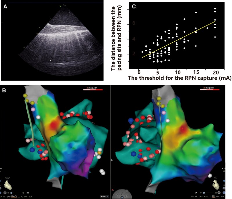
The RPN was detected using ICE. The RPN and its adjacent structures were analysed. The relationship between the RPN’s distance from the superior vena cava (SVC) and its pacing capture threshold was quantified. The safety of SVC isolation guided by the ICE-visualized RPN was evaluated. Thirty-eight people were enrolled in this study. The RPN was visualized by ICE in 92% of patients. It ran through the space between the SVC and the mediastinal pleura and had a ‘straw’-like appearance upon ICE imaging. The course of the RPN was close to the SVC (minimum 1.0 ± 0.4 mm) and the right superior pulmonary vein (minimum 14.1 ± 7.3 mm). There was a positive linear correlation between the RPN’s capture threshold and its distance from the SVC (Spearman’s correlation coefficient = 0.728, < 0.001). SVC isolation was guided by the RPN; none of the patients developed an RPN injury.
Conclusions
RPN can be visualized by ICE in most patients, thus providing a novel approach for the real-time detection of RPN during AF ablation.
Keywords: Right phrenic nerve, Ablation, Intracardiac echocardiography, Atrial fibrillation
Graphical Abstract
Graphical Abstract.
A: The ICE image of the RPN. B: The anatomical relationship between RPN and SVC, RSPV, sinus node in the 3D activation map. C: There was a positive linear correlation between the RPN's capture threshold and its distance from the SVC.
What’s new?
The right phrenic nerve (RPN) can be visualized by intracardiac echocardiography (ICE) in most of the patients during the procedure.
The distance between the pacing site and the RPN is linearly correlated with the threshold for the RPN capture.
The RPN identified by ICE can guide the superior vena cava isolation.
Introduction
Radiofrequency (RF) catheter ablation is the mainstay treatment for symptomatic drug-refractory atrial fibrillation (AF). Pulmonary vein isolation using RF is the most common ablation procedure. Elimination of non-pulmonary vein foci increases the success rate of the procedure. Non-pulmonary vein triggers foci include the superior vena cava (SVC), coronary sinus, posterior wall of the left atrium, crista terminalis, atrial appendage, etc.1 The SVC accounts for a major portion of the non-pulmonary vein foci. Circumferential SVC isolation has improved the outcomes of AF originating from the SVC.2,3 However, right phrenic nerve (RPN) injury is a significant complication associated with SVC isolation, with an incidence of up to 5%.2 The close anatomical relationship between the RPN and SVC makes it more vulnerable to injury during SVC isolation. Multiple modalities are currently used for the early detection of RPN injuries during the procedure. An electrode catheter is placed in the SVC and paces the RPN, while the diaphragmatic function is monitored by right hemidiaphragm movement or compound motor action potentials (CMAPs).5,6However, none of these approaches can directly visualize the RPN in real-time during the procedure.
A phrenic nerve block can quickly and effectively terminate the hiccups. The ultrasound-guided block allows precise visualization and localization of the phrenic nerve. It reduces the incidence of the associated complication.7 Intracardiac echocardiography (ICE) is widely used for the ablation of AF. Therefore, we speculate that ICE in the SVC might visualize the RPN and facilitate SVC isolation without RPN injury. In the present study, we first aimed to delineate the spatial course of the RPN along the SVC using ICE and quantify the relationship between the distance of the RPN from the SVC and its pacing capture threshold. We then evaluated the safety of SVC isolation guided by the RPN visualized by ICE.
Methods
Study population
This study prospectively enrolled 38 patients with drug-refractory paroxysmal or persistent AF who underwent AF ablation at the Beijing Anzhen Hospital between July 2021 and February 2022. Paroxysmal AF (PAF) was defined as AF sustained for <7 days. Persistent AF was defined as continuous AF that persisted for >7 days.8 Written informed consent was obtained from all patients. The study and data collection were performed according to the protocols approved by the ethics committee of Beijing Anzhen Hospital.
Ablation procedure
An uninterrupted anticoagulation approach was used routinely. The procedure was performed under conscious sedation using fentanyl and midazolam. A deflectable decapolar catheter was placed in the coronary sinus. After a single successful transseptal puncture guided by a SoundStar 3D diagnostic ultrasound catheter and CartoSound module (Biosense Webster, Diamond Bar, CA), all patients were empirically administered an unfractionated heparin bolus (100 U/kg) to achieve a target activated clotting time >300 s. A multipolar catheter (PentaRay NAV; Biosense Webster, Diamond Bar, CA, USA) was used to create a 3D shell of the left atrium. Ablation by the irrigated RF catheter (Thermocool Smarttouch™ SF, Biozones Webster, Diamond Bar, CA, USA) was guided by a 3D electroanatomic mapping system (CARTO, Biosense-Webster, Inc.). The ablation strategy has been described in detail previously.9
Electroanatomical mapping of the superior vena cava and right atrium
Fast anatomic mapping of the SVC and right atrium (RA) during sinus rhythm was acquired using the PentaRay catheter and the Confidense module. The junction of the convex RA wall and the straight SVC wall on electroanatomic mapping was defined as the SVC–RA junction. The upper part of the SVC with vein branches was defined as the initial inflow of the SVC, which usually lacks electrical signalling. High-density mapping was performed along the SVC–RA junction during sinus rhythm to reconstruct sinus node activation.10,11 The sinus node region was identified as the region of the earliest atrial activation in sinus rhythm.
Reconstruction of the right phrenic nerve by intracardiac echocardiography and pacing the right phrenic nerve
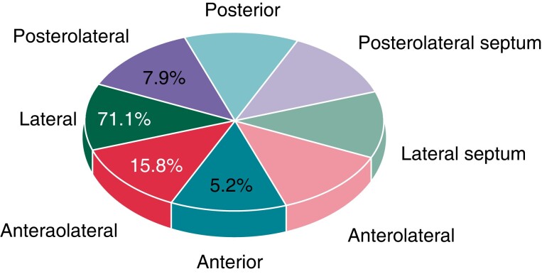
An ultrasound system (GE Vivid IQ) was used to obtain high-quality images. The ICE was placed in the SVC, which was created using electroanatomical mapping. Axial scanning was performed along the theoretical course of the RPN, which is usually located on the lateral wall of the SVC. A typical ICE image of the RPN in the longitudinal view presents a ‘straw’ pattern.12 High-resolution ultrasound scans can accurately distinguish the RPN from adjacent structures. The ICE image of the RPN was integrated into the electroanatomical mapping of the SVC, which allowed the delineation of the course of the RPN and other structures. To precisely localize the course of the RPN, we divided the SVC into eight segments: anterior, anterolateral, lateral, posterolateral, posterior, anterolateral septal, lateral septal, and posterolateral septal (Figure 1).
Figure 1.
Location of the RPN in the SVC. In 5.2%,15.8%,71.1%, and 7.9% of patients, the RPN is located on the anterior, anterolateral, lateral, and posterolateral walls of the SVC, respectively. RPN, right phrenic nerve; SVC, superior vena cava.
Bipolar pacing of the RPN was performed using an ablation catheter in the SVC. The threshold for the RPN capture was defined as a stable diaphragmatic movement with a constant amplitude of the diaphragmatic CMAP. We applied 5–10 g contact force to measure the pacing threshold of RPN capture. The pacing protocol consisted of incremental pacing currents (from 1 to 20 mA) with a 2 ms pulse width and a cycle length of 1000 ms–2000ms. The distance between the pacing site and the RPN was measured using ICE.
Superior vena cava isolation
SVC isolation relied on the operator’s discretion. It was performed by ablating 5 mm away from the sinus node with a power of 35 W, guided by the ablation index.13 Ablation started in the septal wall of the SVC–RA junction with a target ablation index of 400. The ablation site should be ≥5 mm from the RPN, guided by ICE. When the ablation site was 5 mm from the RPN, the ablation index decreased to 300. Phrenic nerve injury (PNI) was defined as previously.5 Diaphragmatic CMAP and the movement of the diaphragm were monitored during the SVC isolation procedure. Ablation was discontinued if the observed CMAP amplitude decreased by ≥35% from baseline or the movement of the diaphragm was weakened.5
Statistical analysis
Statistical analyses were performed using SPSS (version 22). The results are presented as mean ± standard deviation or percentages. A positive Spearman’s correlation value was reported in the scatter plot. Simple linear regression was also utilized. Significance was tested against the null hypothesis of no association. Statistical significance was set at P < 0.05.
Results
Demographic and clinical characteristics of the patients
A total of 38 patients were enrolled in the study. The baseline patient characteristics are presented in Table 1. The mean age of the patients was 63.2 ± 7.8. Of these patients, 47.4% had PAF. The mean CHA2DS2-VASc score was 2.13 ± 1.51.
Table 1.
The baseline characteristics of patients
| Number of patients | 38 |
|---|---|
| Age (years) | 63.2 ± 7.8 |
| Gender (male/female) | 24/14 |
| Hypertension | 27/38 |
| Diabetes | 6/28 |
| Obesitya | 13/28 |
| Left ventricular ejection fraction, % | 60.8 ± 8.0 |
| PAF/PerAF | 18/20 |
| CHA2DS2-VASc scoreb | 2.13 ± 1.51 |
BMI, body mass index; PAF, paroxysmal atrial fibrillation; PerAF, persistent atrial fibrillation.
An individual would be considered to be obese if his/her BMI was in the range of 30–35 or greater. bCHA2DS2-VASc score was defined as previously.9
The identification and the course of right phrenic nerve along the superior vena cava
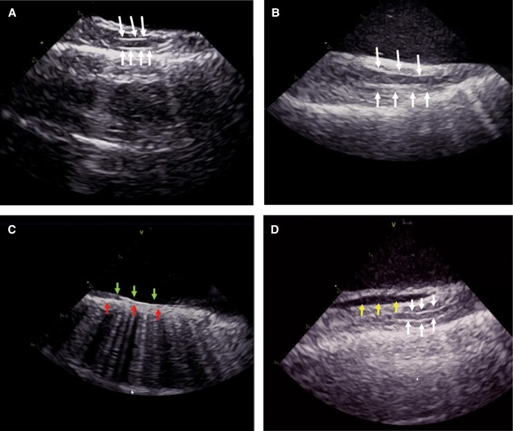
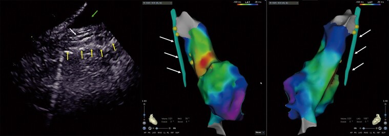
The RPN was visualized using ICE in 35 (92%) patients. The ICE image of the RPN in the longitudinal view of the SVC presents as a straw, representing a typical echo image of a large nerve trunk (Figure 2). The RPN ran through the space between the SVC and the mediastinal pleura. The mediastinal pleura showed a hyperechoic structure on the ICE image. It was quickly identified once ICE was introduced into the SVC, and axial scanning was performed along the lateral wall of the SVC. Thus, the space between the SVC and mediastinal pleura was used as an anatomical marker to guide the identification of the RPN. The lowest pacing threshold for RPN capture is achieved when the ablation catheter is placed close to the ‘straw’ pattern in the SVC (Figure 3). This confirmed that the ‘straw’ structure identified in ICE was the RPN. The RPN could not be identified in three out of 38 (8%) patients due to a narrowed space between the SVC and the mediastinal pleura (<1 mm) (Figure 2C); it was difficult to distinguish the RPN from the mediastinal pleura in these cases. All three patients had a low pacing threshold (<5 mA) in the lateral wall of the SVC; in the site with the lowest pacing threshold, there was no ‘straw’ pattern in the ICE imaging.
Figure 2.
The intracardiac echocardiography (ICE) image of the right phrenic nerve (RPN). The RPN is a round, thin structure with a ‘straw’-like appearance, that is centrally hypoechoic and peripherally hyperechoic between the superior vena cava (SVC) and the mediastinal pleura. The arrow indicates the RPN (Figure 2A–B). Bottom row of arrows indicate the mediastinal pleura and up row of arrows indicate the intima of SVC, the RPN could not be identified due to a narrowed space between the SVC and the mediastinal pleura (<1 mm) (Figure 2C). Arrows on left indicate reflexed pericardium and arrows on right indicate the RPN; the fluid separates the visceral pericardium from the parietal pericardium in the inferior part of the SVC (Figure 2D).
Figure 3.
The lowest pacing threshold for right phrenic nerve (RPN) capture. The lowest pacing threshold for RPN capture is achieved when the ablation catheter is placed close to the ‘straw’ pattern in the superior vena cava (SVC). Left image: the RPN imaging under intracardiac echocardiography (ICE). The up row of arrow indicates the RPN, and the bottom row of arrows indicates the mediastinal pleura. Middle and right images: the same patient’s 3D activation maps of the right atrium (RA) and SVC in right anterior oblique (RAO) 45° and RAO 145° views. The dots indicate the pacing site and the arrows indicate the RPN integrated into the electroanatomical shell.
The diameter of the RPN, as measured by ICE, was 1.3 ± 0.40 mm. Of the RPNs measured, 71.1% were located on the lateral wall. The RPN ran nearly in the middle of the space between the SVC and mediastinal pleura. The course of the RPN was close to the SVC (minimum 1.0 ± 0.4 mm). The distance between the RPN and SVC usually increases in the craniocaudal direction (Figure 4), while we observed the shortest distance between the RPN and SVC in the middle of the SVC in four patients. Pericardial reflection usually extends to the SVC. In three patients, pericardial fluid accumulated in the pericardial reflection of the SVC (Figure 2D). This fluid separated the visceral pericardium from the parietal pericardium in the inferior part of the SVC, resulting in an increased distance between the RPN and the SVC.
Figure 4.
The anatomical relationship of the right phrenic nerve (RPN) and the superior vena cava (SVC). The distance between the RPN and the SVC is increased from the craniocaudal direction in the 3D activation map of the right atrium (RA) and SVC in right anterior oblique (RAO) 30° and left anterior oblique (LAO) 165° views. Left image: the RPN imaging under intracardiac echocardiography (ICE). The middle arrow indicates the RPN, the bottom row of arrows indicate the mediastinal pleura, and the up row of arrow indicates the pericardial fluid. Middle and right images: the same patient’s 3D activation maps of the RA and SVC in RAO 30° and LAO 165° view. The arrows indicate the RPN integrated into the electroanatomical shell.
The right phrenic nerve, the sinus node, and the right pulmonary vein
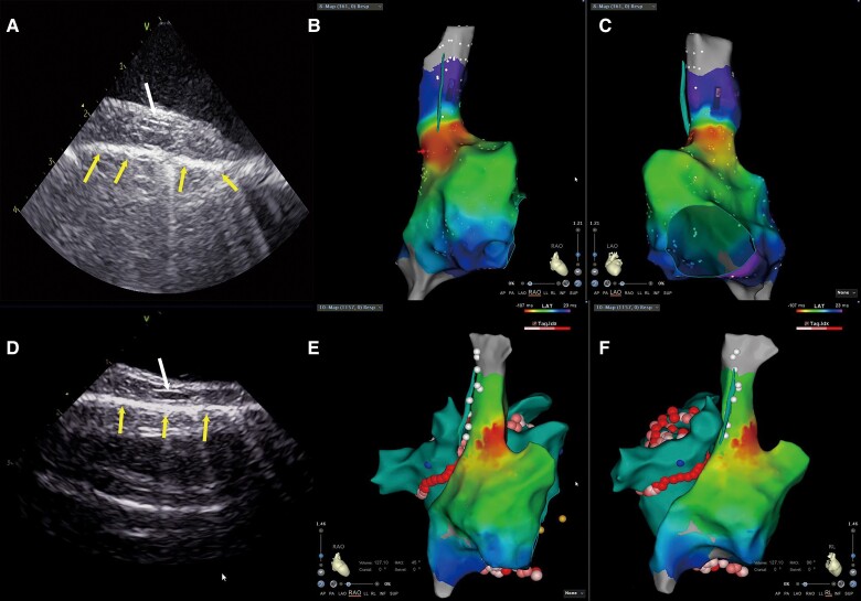
Superior vena cava mapping was performed during sinus rhythm. The majority of the sinus node is located at the junction of the SVC and the RA (Figure 5B and C). The distance of the RPN from the superior part of the sinus node was 12.7 ± 5.4 mm, and the minimal distance was 6.4 mm.
Figure 5.
The anatomical relationship of the right phrenic nerve (RPN) and right superior pulmonary vein (RSPV) and sinus node. (A and D) illustrate RPN imaging under intracardiac echocardiography (ICE), where the up row of arrow indicates the RPN, and the bottom row of arrows indicate the mediastinal pleura. The anatomical distance from the RPN to the sinus node is quite close in the 3D activation map of the right atrium (RA) and superior vena cava (SVC) in the right anterior oblique (RAO) view (B) and left anterior oblique (LAO) view (C). The anatomical distance from the RPN to the RSPV is quite close in the 3D activation map of the RA and SVC in the RAO (E) and right lateral (RL) (F) views.
The ICE image of the RPN was integrated into the electroanatomic shell of the left atrium, which allowed measurement of the distance between the RPN and the right pulmonary vein. First, we measured the shortest distance between the RPN and the right pulmonary vein ablation point, which is usually located in the antrum of the right superior pulmonary vein (RSPV). The average distance between the RPN and the ablation point was 24.9 ± 7.2 mm, and the minimal space was 5.0 mm. We then measured the shortest distance between the RPN and the right pulmonary vein. The shortest distance is between the RPN and the RSPV in all patients (Figure5E and F); the average distance was 14.1 ± 7.3 mm, and 5.7% of patients had a length of less than 5.0 mm.
The pacing threshold of the right phrenic nerve capture
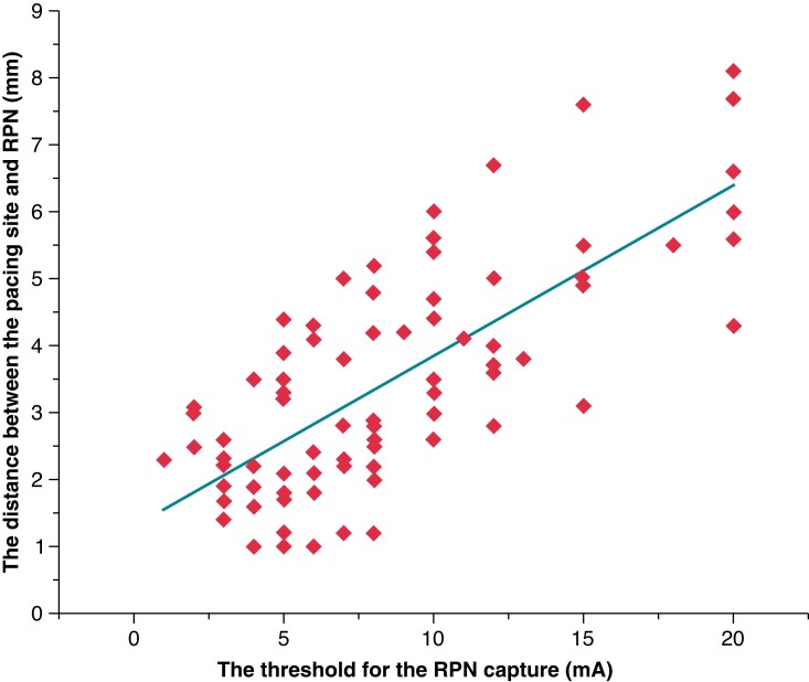
The pacing manoeuvre is applied to monitor the function of the RPN during SVC isolation, but it cannot precisely differentiate the near-field from the far-field capture of the RPN. We analysed the relationship between the pacing threshold of RPN capture and the distance between the catheter tip and the RPN. The mean contact force for measuring the pacing threshold of RPN capture was 7.4 ± 0.3 g. The distance between the pacing site and the RPN is strongly correlated with the threshold for RPN capture (Spearman correlation = 0.728, < 0.001) (see Supplementary material online, Figure 6). The distance from the phrenic nerve increased by 0.26 mm for each 1 mA increase in pacing threshold current. If the pacing threshold of RPN capture was 20 mA, 83.3% of the distance was ≥5 mm.
Figure 6.
Scatter plot between the right phrenic nerve (RPN) pacing threshold and distance from the pacing site. The distance from the pacing site to the RPN is significantly correlated with the RPN pacing threshold (Spearman’s correlation coefficient = 0.728, P < 0.001).
Isolation of the superior vena cava
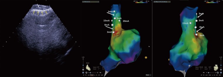
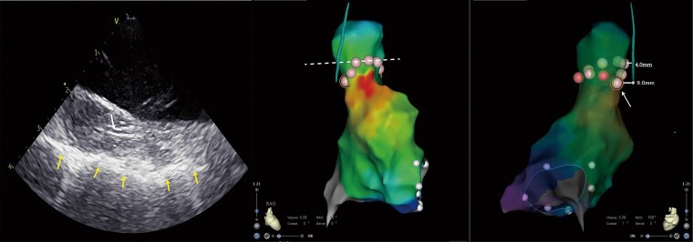
Superior vena cava isolation was performed in 10 patients. The combined methods of the RPN pacing manoeuvre and RPN imaging by ICE guided the procedure. The minimal distance between the RPN and the ablation point was 5 mm and the ablation index was 300. The RPN mapping by ICE and the activation mapping of the sinus node were integrated into the 3D shell of the SVC, which allowed to design a personalized ablation line for SVC isolation avoiding the injury of the RPN and the sinus node. Figure 7 shows a representative circumferential SVC isolation line in one patient. The dotted line indicated the regular circumferential SVC isolation ablation line. The nearest distance from the SVC’s regular ablation point to the RPN was 4 mm. To avoid RPN injury, we did not adopt the regular circumferential SVC isolation line in this case. The arrow in Figure 7 indicates the last ablation point, which is located behind the sinus node and close to the RPN, but 9 mm away from it. We did not observe the decreased CMAP and the weakness of the diaphragm movement during the SVC ablation procedure in all patients. No RPN injury or sinus node injury developed during the SVC isolation procedure in all patients.
Figure 7.
Circumferential superior vena cava (SVC) ablation using intracardiac echocardiography (ICE). Left image: the right phrenic nerve (RPN) imaging under ICE. The up row of arrow indicates the RPN, and the bottom row of arrows indicate the mediastinal pleura. Middle and right images: the same patient’s circumferential SVC ablation in the 3D activation map of the right atrium (RA) and SVC in right anterior oblique (RAO) 45° and RAO 168° views. The dotted line indicates the regular circumferential superior vena cava isolation ablation line. The arrow indicates the last ablation point which is the closest ablation point of our actual circumferential superior vena cava ablation.
Discussion
The present study demonstrated that (i) the RPN could be visualized by ICE in most of the patients during the procedure; (ii) the distance between the pacing site and the RPN was linearly correlated with the threshold for RPN capture; and (iii) the RPN identified by ICE could guide SVC isolation.
Right PNI is a common complication of ablation for AF. Despite advances in ablation devices, strategies, and monitoring methods, the incidence of RPN injury during the procedure remains at 3.5% in the cryoballoon ablation procedure.4 Moreover, early abortion of ablation due to the RPN injury might result in the pulmonary vein electrical reconnection and, consequently, arrhythmia recurrence. 14–16 The proximity of the RPN to the SVC and the RSPV makes it vulnerable to injury from RF ablation or cryoablation. Understanding the spatial relationships between the RPN and nearby anatomical structures is critical for preventing RPN injuries. The pacing manoeuvre in the SVC is usually performed during the procedure to identify the RPN and is tagged in the electroanatomic shell of the RA. Therefore, the course of the RPN can be displayed in the electroanatomic mapping system to guide ablation. However, this manoeuvre does not directly visualize the RPN, and it cannot distinguish far-field RPN capture from near-field capture. Thus, the pacing manoeuvre provides only a crude course of the RPN outside of the SVC. Computed tomography (CT) was used to assess the cardiac anatomy before the ablation procedure in previous studies.17,18 Computed tomography with improved temporal and spatial resolution can reconstruct the course of the RPN. Computed tomography images are merged with the electroanatomic mapping using the Carto Merge image integration module, which allows observation of the course of the RPN during the ablation procedure and avoids injury to the RPN. The sensitivity of RPN detection by CT was distinct, and the RPN was identified in a small percentage of patients.19 Moreover, CT images are not real-time monitoring methods for the RPN; the course of the RPN may be distorted by inaccurate merge manoeuvre and translocation of the electroanatomic mapping.
Ultrasonography is an alternative technique for imaging peripheral nerves. High-frequency probes provide a higher spatial resolution (0.2–0.3 mm) than CT images (0.4 mm).20,21 Ultrasound has long been used to detect and visualize the phrenic nerve of the neck. Ultrasound-guided block of the phrenic nerve is a traditional approach for terminating hiccups in clinical practice.7 More recently, Piotrowski et al.22 reported that ultrasound could visualize vague nerves and guide extra-cardiac vagal stimulation during cardioneuroablation. ICE is widely used in interventional procedures, particularly for AF ablation. When ICE is introduced in the SVC and placed close to the lateral wall of the SVC, it allows direct visualization of the RPN.
In the present study, we were able to observe a typical ultrasound image of the nerve trunk outside the SVC using ICE in most patients. In the transverse section, the nerve trunk revealed small hypoechoic areas separated by hyperechoic septae, giving a ‘honeycomb-like’ appearance.23 Intracardiac echocardiography in the SVC only provides longitudinal sections of the nerve trunk, which presents ‘a straw’ or ‘bundle of straws’ appearance.12 The hypoechoic areas represent nerve fascicles, while the echogenic septae represent interfascicular perineurium. Several hints confirmed that the above structure outside the SVC was the RPN. First, the dimensions of the structure were 1.4 ± 0.4 mm, which was slightly wider than the phrenic nerve’s diameter in the neck. The phrenic nerve originates in the cervical spine (C3–C5),24 and it is reasonable that the RPN is thicker in the thorax than in the neck. Secondly, in a human cadaver study, the RPN was found to run through a small space between the parietal pericardium and the mediastinal pleura.25 The mediastinal pleura has a hyperechoic feature; therefore, the small space for accommodating the RPN is easily identified by ICE in the SVC. No other structure needs to be distinguished from the RPN in this space. Moreover, the colour Doppler by ICE excluded that the ‘straw”-like structure was a small vessel. Finally, the lowest pacing threshold was achieved when the ablation catheter was placed to close the ‘straw’ pattern in the SVC; it further confirmed that the ‘straw’ appearance identified by ICE was the RPN.
In the present study, ICE could visualize the RPN in 92% of patients, which was superior to the CT approach. The RPN could not be identified by ICE in only three patients, in whom the space between the SVC and the mediastinal pleura was too narrow (<1 mm). Therefore, it was challenging to distinguish the RPN from the mediastinal pleura in these cases. In this scenario, the RPN is very close to the SVC, and the risk of RPN injury substantially increases during the SVC isolation procedure.
ICE has the advantage of a real-time display of the RPN. Its integration into the electroanatomical mapping of the right and left atria provides a novel approach to delineate the spatial relationship between the RPN and its surrounding anatomical structures. The present study showed that most RPNs were located in the lateral wall of the SVC, which is consistent with previous studies.26 Although the distance between the RPN and SVC usually increases in the craniocaudal direction, few patients present the shortest distance in the middle part of the SVC, which might increase the risk of RPN injury during ablation in this area. The shortest distance between the RPN and the right pulmonary vein was in the RSPV in all patients, which agreed with the fact that RPN injury usually occurred during cryoablation of the RSPV. Intriguingly, most ablation points were 1 cm from the RPN in the present study. Thus, RF ablation of the antrum and carina of the RSPV seldom caused RPN injury, which was consistent with clinical observations. Moreover, 5.7% of patients had a minimal distance of <5 mm between the RPN and the RSPV, suggesting that avoidance of deep ablation in the RSPV, such as balloon cryoablation, would substantially reduce the risk of RPN injury. The sinus node may be damaged during SVC isolation due to the ablation sites close to it.27 In the present study, we applied high-density mapping to delineate the precise location of the sinus node.10,11 None of the patients had an injury of the sinus node during SVC isolation.
The pacing manoeuvre in the SVC is commonly utilized to identify the RPN in clinical practice. Low-output and high-output pacing were used to distinguish the far-field from the near-field capture of the RPN. For example, one study by Tomoyuki et al.28 proposed that 20 mA/2.0 ms pacing capture was the far-field capture and 5 mA/2.0 ms pacing capture was the near-field capture.
This approach enabled SVC isolation without RPN injury in their study. However, this approach cannot precisely determine the far-field and near-field capture of the RPN if the course of the RPN in the SVC is not visualized. In the present study, real-time identification of the RPN by ICE was able to quantify the relationship between RPN capture and the distance of the catheter tip from the RPN. Our data showed that the distance between the pacing site and the RPN was linearly correlated with the threshold for RPN capture. If the pacing threshold for the RPN capture was ≥20 mA/2.0 ms, the distance between the pacing site and the RPN was usually ≥5 mm. In some patients, it is inevitable that the catheter tip must ablate the SVC lateral wall close to the RPN during SVC isolation. Real-time visualization of the RPN by ICE allows the design of an optimized ablation line for SVC isolation to avoid RPN injury. In the present study, we created an ablation point in the SVC, 5 mm away from the RPN; the targeted ablation index was 300 and there was no RPN injury. Thus, our study provides a novel approach for isolating the SVC.
Limitations
The main limitation of the present study was the small sample size. Therefore, the location of the RPN, as identified by ICE, should be validated in a larger sample. The incidence of PNI is higher in cryoballoon ablation than in RF ablation. Therefore, the value and significance of this technique in PNI associated with cryoballoon ablation need to be further evaluated. In addition, whether the visualization and mapping of the RPN using ICE are superior to the standard CMAP or pacing techniques require further controlled clinical studies in the future.
Conclusion
RPN injury is a complication of AF ablation. Visualizing the course of the RPN and its surrounding structures in real-time during the ablation procedure would substantially reduce the risk of RPN injury. The present study demonstrates that real-time visualization of the RPN by ICE during the procedure is feasible in most AF patients, thus providing a novel approach for avoiding RPN injury during the ablation procedure.
Supplementary material
Supplementary material is available at Europace online.
Supplementary Material
Contributor Information
Xinmeng Liu, Department of Cardiology, Beijing Anzhen Hospital, Capital Medical University, No. 2, Anzhen Road, Chaoyang District, 100029 Beijing, China; National Clinical Research Center for Cardiovascular Diseases, No. 2, Anzhen Road, Chaoyang District, 100029 Beijing, China.
Rong Lin, North China Medical & Health Group XingTai General Hospital, Xingtai, China.
Xiaodong Peng, Department of Cardiology, Beijing Anzhen Hospital, Capital Medical University, No. 2, Anzhen Road, Chaoyang District, 100029 Beijing, China; National Clinical Research Center for Cardiovascular Diseases, No. 2, Anzhen Road, Chaoyang District, 100029 Beijing, China.
Xuesi Wang, Department of Cardiology, Beijing Anzhen Hospital, Capital Medical University, No. 2, Anzhen Road, Chaoyang District, 100029 Beijing, China; National Clinical Research Center for Cardiovascular Diseases, No. 2, Anzhen Road, Chaoyang District, 100029 Beijing, China.
Yukun Li, Department of Cardiology, Beijing Anzhen Hospital, Capital Medical University, No. 2, Anzhen Road, Chaoyang District, 100029 Beijing, China; National Clinical Research Center for Cardiovascular Diseases, No. 2, Anzhen Road, Chaoyang District, 100029 Beijing, China.
Xiaoxia Liu, Department of Cardiology, Beijing Anzhen Hospital, Capital Medical University, No. 2, Anzhen Road, Chaoyang District, 100029 Beijing, China; National Clinical Research Center for Cardiovascular Diseases, No. 2, Anzhen Road, Chaoyang District, 100029 Beijing, China.
Wei Wang, Department of Cardiology, Beijing Anzhen Hospital, Capital Medical University, No. 2, Anzhen Road, Chaoyang District, 100029 Beijing, China; National Clinical Research Center for Cardiovascular Diseases, No. 2, Anzhen Road, Chaoyang District, 100029 Beijing, China.
Ronghui Yu, Department of Cardiology, Beijing Anzhen Hospital, Capital Medical University, No. 2, Anzhen Road, Chaoyang District, 100029 Beijing, China; National Clinical Research Center for Cardiovascular Diseases, No. 2, Anzhen Road, Chaoyang District, 100029 Beijing, China.
Rong Bai, Banner—University Medical Center Phoenix, Phoenix, AZ, USA.
Changsheng Ma, Department of Cardiology, Beijing Anzhen Hospital, Capital Medical University, No. 2, Anzhen Road, Chaoyang District, 100029 Beijing, China; National Clinical Research Center for Cardiovascular Diseases, No. 2, Anzhen Road, Chaoyang District, 100029 Beijing, China.
Yanfei Ruan, Department of Cardiology, Beijing Anzhen Hospital, Capital Medical University, No. 2, Anzhen Road, Chaoyang District, 100029 Beijing, China; National Clinical Research Center for Cardiovascular Diseases, No. 2, Anzhen Road, Chaoyang District, 100029 Beijing, China.
Nian Liu, Department of Cardiology, Beijing Anzhen Hospital, Capital Medical University, No. 2, Anzhen Road, Chaoyang District, 100029 Beijing, China; National Clinical Research Center for Cardiovascular Diseases, No. 2, Anzhen Road, Chaoyang District, 100029 Beijing, China.
Funding
This work was supported by the National Science Foundation of China (grant nos. 81870244, 82170318, 81770318) and the Beijing Municipal Science and Technology Commission (Z181100001718174).
Data availability
The data underlying this article will be shared on reasonable request to the corresponding author.
References
- 1. Santangeli P, Marchlinski FE. Techniques for the provocation, localization, and ablation of non-pulmonary vein triggers for atrial fibrillation. Heart rhythm 2017;14:1087–96. [DOI] [PubMed] [Google Scholar]
- 2. Miyazaki S, Takigawa M, Kusa S, Kuwahara T, Taniguchi H, Okubo Ket al. . Role of arrhythmogenic superior vena cava on atrial fibrillation. J. Cardiovasc. Electrophysiol 2014;25:380–6. [DOI] [PubMed] [Google Scholar]
- 3. Chang HY, Lo LW, Lin YJ, Chang SL, Hu YF, Feng ANet al. . Long-term outcome of catheter ablation in patients with atrial fibrillation originating from the superior vena cava. J. Cardiovasc. Electrophysiol 2012;23:955–61. [DOI] [PubMed] [Google Scholar]
- 4. Abugattas JP, de Asmundis C, Iacopino S, Salghetti F, Takarada K, Coutiño HEet al. . Phrenic nerve injury during right inferior pulmonary vein ablation with the second-generation cryoballoon: clinical, procedural, and anatomical characteristics. Europace. 2018;20:e156-e163. [DOI] [PubMed] [Google Scholar]
- 5. Parikh V, Kowalski M. Comparison of phrenic nerve injury during atrial fibrillation ablation between different modalities, pathophysiology and management. J Atr Fibrillation 2015;8:1314. [DOI] [PMC free article] [PubMed] [Google Scholar]
- 6. Lakhani M, Saiful F, Parikh V, Goyal N, Bekheit S, Kowalski M. Recordings of diaphragmatic electromyograms during cryoballoon ablation for atrial fibrillation accurately predict phrenic nerve injury. Heart Rhythm 2014;11:369–74. [DOI] [PubMed] [Google Scholar]
- 7. Blichfeldt-Eckhardt MR, Laursen CB, Berg H, Holm JH, Hansen LN, Ørding Het al. . A randomised, controlled, double-blind trial of ultrasound-guided phrenic nerve block to prevent shoulder pain after thoracic surgery. Anaesthesia. 2016;71:1441–8. [DOI] [PubMed] [Google Scholar]
- 8. Hindricks G, Potpara T, Dagres N, Arbelo E, Bax JJ, Blomström-Lundqvist Cet al. . 2020 ESC guidelines for the diagnosis and management of atrial fibrillation developed in collaboration with the European Association for Cardio-Thoracic Surgery (EACTS): the task force for the diagnosis and management of atrial fibrillation of the European Society of Cardiology (ESC) developed with the special contribution of the European Heart Rhythm Association (EHRA) of the ESC. Eur Heart J 2021;42:373–498. [DOI] [PubMed] [Google Scholar]
- 9. Dong JZ, Sang CH, Yu RH, Long DY, Tang RB, Jiang CXet al. . Prospective randomized comparison between a fixed ‘2C3L’approach vs. stepwise approach for catheter ablation of persistent atrial fibrillation. Europace 2015;17:1798–806. [DOI] [PubMed] [Google Scholar]
- 10. Rottner L, Metzner A, Ouyang F, Heeger C, Hayashi K, Fink Tet al. . Direct comparison of point-by-point and rapid ultra-high-resolution electroanatomical mapping in patients scheduled for ablation of atrial fibrillation. J. Cardiovasc. Electrophysiol 2017;28:289–97. [DOI] [PubMed] [Google Scholar]
- 11. Vetulli HM, Elizari MV, Naccarelli GV, Gonzalez MD. Cardiac automaticity: basic concepts and clinical observations. J Interv Card Electrophysiol. 2018;52: 263–70. [DOI] [PubMed] [Google Scholar]
- 12. Lawande AD, Warrier SS, Joshi MS. Role of ultrasound in evaluation of peripheral nerves. Ind J Radiol Imaging 2014;24:254–8. [DOI] [PMC free article] [PubMed] [Google Scholar]
- 13. Hussein A, Das M, Riva S, Morgan M, Ronayne C, Sahni Aet al. . Use of ablation index-guided ablation results in high rates of durable pulmonary vein isolation and freedom from arrhythmia in persistent atrial fibrillation patients: the PRAISE study results. Circ Arrhythm Electrophysiol 2018;11:e006576. [DOI] [PubMed] [Google Scholar]
- 14. Heeger CH, Popescu SȘ, Sohns C, Pott A, Metzner A, Inaba Oet al. . Impact of cryoballoon application abortion due to phrenic nerve injury on reconnection rates: a YETI subgroup analysis. Europace 2022;00:1–8. [DOI] [PMC free article] [PubMed] [Google Scholar]
- 15. Heeger CH, Popescu SS, Saraei R, Kirstein B, Hatahet S, Samara Oet al. . Individualized or fixed approach to pulmonary vein isolation utilizing the fourth-generation cryoballoon in patients with paroxysmal atrial fibrillation: the randomized INDI-FREEZE trial. Europace 2022;24:921–7. [DOI] [PMC free article] [PubMed] [Google Scholar]
- 16. Miyazaki S, Kajiyama T, Watanabe T, Hada M, Yamao K, Kusa Set al. . Characteristics of phrenic nerve injury during pulmonary vein isolation using a 28-mm second-generation cryoballoon and short freeze strategy. J Am Heart Assoc 2018; 7:e008249. [DOI] [PMC free article] [PubMed] [Google Scholar]
- 17. Guthaner DF, Wexler L, Harell G. CT demonstration of cardiac structures. Am. J. Roentgenol 1979;133:75–81. [DOI] [PubMed] [Google Scholar]
- 18. Maj R, Borio G, Ströker E, Sieira J, Rizzo A, Galli Aet al. . Phrenic nerve palsy during right-sided pulmonary veins cryoapplications: new insights from pulmonary vein anatomy addressed by computed tomography. J Interv Card Electrophysiol 2021;60:85–92. [DOI] [PubMed] [Google Scholar]
- 19. Wang YJ, Liu L, Zhang MC, Sun H, Zeng H, Yang P. Imaging of pericardiophrenic bundles using multislice spiral computed tomography for phrenic nerve anatomy. J. Cardiovasc. Electrophysiol 2016;27:961–71. [DOI] [PubMed] [Google Scholar]
- 20. Moretti R, Pizzi B. Ultrasonography of the optic nerve in neurocritically ill patients. Acta Anaesthesiol. Scand. 2011;55: 644–52. [DOI] [PubMed] [Google Scholar]
- 21. Nikolaou K, Flohr T, Knez A, Rist C, Wintersperger B, Johnson Tet al. . Advances in cardiac CT imaging: 64-slice scanner. J Interv Card Electrophysiol. 2004;20: 535–40. [DOI] [PubMed] [Google Scholar]
- 22. Piotrowski R, Zuk A, Baran J, Sikorska A, Krynski T, Kulakowski P. Ultrasound-guided extracardiac vagal stimulation—new approach for visualization of the vagus nerve during cardioneuroablation. Heart Rhythm 2022;19:1247–52. [DOI] [PubMed] [Google Scholar]
- 23. Gray AT, Warltier DC. Ultrasound-guided regional anesthesia: current state of the art. Anesthesiology 2006;104:368–73. [DOI] [PubMed] [Google Scholar]
- 24. Goshgarian HG, Rafols JA. The phrenic nucleus of th albino rat: a correlative HRP and Golgi study. J Comp Neurol 1981;201:441–56. [DOI] [PubMed] [Google Scholar]
- 25. Sánchez-Quintana D, Cabrera JA, Climent V, Farré J, Weiglein A, Ho SY. How close are the phrenic nerves to cardiac structures? Implications for cardiac interventionalists. J. Cardiovasc. Electrophysiol 2005;16:309–13. [DOI] [PubMed] [Google Scholar]
- 26. Chen Y, Wang Z, Sun L, Chen X, Wang X, Li Ret al. . Efficacy and safety of segmental radiofrequency ablation for isolation of the superior vena cava in patients with atrial fibrillation. Zhonghua Xin Xue Guan Bing Za Zhi 2021;49:229–35. [DOI] [PubMed] [Google Scholar]
- 27. Chen G, Dong JZ, Liu XP, Zhang XY, Long DY, Sang CHet al. . Sinus node injury as a result of superior vena cava isolation during catheter ablation for atrial fibrillation and atrial flutter. Pacing Clin. Electrophysiol. 2011;34: 163–70. [DOI] [PubMed] [Google Scholar]
- 28. Arai T, Hojo R, Kitamura T, Fukamizu S. A new method of superior vena cava isolation without phrenic nerve injury by longitudinal ablation parallel to the phrenic nerve: a case report. Eur Heart J Case Rep 2020;4:1. [DOI] [PMC free article] [PubMed] [Google Scholar]
Associated Data
This section collects any data citations, data availability statements, or supplementary materials included in this article.
Supplementary Materials
Data Availability Statement
The data underlying this article will be shared on reasonable request to the corresponding author.


