Abstract
Aims
The goal was to evaluate tibiofemoral knee joint kinematics during stair descent, by simulating the full stair descent motion in vitro. The knee joint kinematics were evaluated for two types of knee implants: bi-cruciate retaining and bi-cruciate stabilized. It was hypothesized that the bi-cruciate retaining implant better approximates native kinematics.
Methods
The in vitro study included 20 specimens which were tested during a full stair descent with physiological muscle forces in a dynamic knee rig. Laxity envelopes were measured by applying external loading conditions in varus/valgus and internal/external direction.
Results
The laxity results show that both implants are capable of mimicking the native internal/external-laxity during the controlled lowering phase. The kinematic results show that the bi-cruciate retaining implant tends to approximate the native condition better compared to bi-cruciate stabilized implant. This is valid for the internal/external rotation and the anteroposterior translation during all phases of the stair descent, and for the compression-distraction of the knee joint during swing and controlled lowering phase.
Conclusion
The results show a better approximation of the native kinematics by the bi-cruciate retaining knee implant compared to the bi-cruciate stabilized knee implant for internal/external rotation and anteroposterior translation. Whether this will result in better patient outcomes remains to be investigated.
Cite this article: Bone Joint Res 2023;12(4):285–293.
Keywords: Stair descent, Total knee arthroplasty, Knee laxity, Bi-cruciate retaining implants, Knee kinematics, kinematics, knee joints, Knee, laxity, valgus, knee implants, knee joint kinematics, cruciate retaining implants, muscle forces
Article focus
Imposing full stair descent motions on cadaveric knee specimens.
Reporting knee kinematic data in six degrees of freedom during stair descent.
Comparing knee kinematics in native and implanted conditions during stair descent.
Key messages
Imposing the full stair descent with physiological muscle forces in vitro is shown to be possible in the adjusted dynamic knee rig.
Knee kinematics were captured in six degrees of freedom for native knee joints and knee joints implanted with bi-cruciate retaining implants and bi-cruciate stabilized implants.
Comparative analysis between native kinematics and implanted kinematics show the ability of the bi-cruciate retaining implant to better mimic native conditions.
Strengths and limitations
This is the first study to perform a complete stair descent on a cadaver specimen in a knee rig on 20 fresh-frozen specimens.
This is the first study to report on knee kinematics in all six degrees of freedom during the full stair cycle.
A limitation is that the quadriceps force is applied as one unit instead of its four separate heads, and that scaled-down muscle loading profiles are used to assure the integrity of the ligament fibres.
Introduction
Preclinical prospective studies of total knee arthroplasty (TKA) implants are critical in understanding implanted knee joint kinematics. Today, survivorship of TKA is 82% for 25 years.1,2 However, this implies TKA failure for many patients. A wide variety of reasons for TKA failure are reported, including loosening, infection, and instability.3 The latter has a major negative impact on patient satisfaction.4,5 Patients suffering from instability after TKA typically complain about problems when performing activities that incur significant transverse or torsion forces in the knee joint, such as descending stairs and walking on sloped or uneven surfaces.6
Knee joint kinematics during stair descent can be investigated in vivo or in vitro. In vivo measurements include radiograph fluoroscopy to assess the kinematics of the TKA.7-9 These techniques are very accurate, but have the downside that only TKA kinematics can be investigated; no native kinematics can be measured due to the limited X-ray exposure time for patients. Therefore, in vitro tests are chosen.
One in vitro test in 2015 studied anteroposterior (AP) stability in the knee joint during stair descent while imposing quadriceps and hamstrings forces.10 Due to simulator limitations, a full motion of the stair descent was not possible, and only selected phases of the descent were simulated: the phase before and after weight acceptance at 15° of knee flexion. The study reported AP translation and internal/external (IE) rotation with and without quadriceps activation for different types of knee implants.
Due to simulator limitations in the typically used Oxford Knee Rig types, the UGent Knee Rig (UGKR) has been developed with the ability to impose a wider range of motion.11,12 By moving the ankle joint in the sagittal plane, it is possible to simulate a full stair descent motion. Therefore, a cadaveric pilot study is set up for this paper using the UGKR with the intended advantage of having a full stair descent cycle, instead of the selected phases reported in existing literature.10
Different stair negotiation techniques are reported in literature, including the standard step-over-step, but also step-by-step, as chosen by elderly and disabled people.13 In the current research, a step-over-step stair descent is chosen. This study was designed to answer the following questions: 1) can the knee joint kinematics during stair descent be captured during the full stair descent cycle?; and 2) do the tibiofemoral kinematics after bi-cruciate retaining (BCR) and bi-cruciate stabilized TKA resemble native kinematics?
Methods
This study was designed to compare tibiofemoral kinematics during stair descent before and after TKA. Two different types of implants are included in the study: 1) bi-cruciate retaining (BCR) where both cruciate ligaments are retained; and 2) bi-cruciate stabilized (BCS), where both cruciate ligaments are cut and a post-cam mechanism is used to prevent posterior subluxation of the tibia in flexion and to restore femoral rollback.
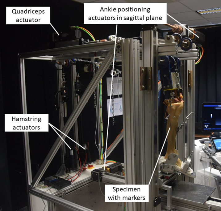
As implant design contributes to knee kinematics,14 we decided to use a single-implant series (Journey II; Smith & Nephew, USA) where the BCR and BCS implants were selected. Both implants were placed according to the guidelines of the manufacturer. Moreover, only paired left and right specimens were chosen, making it possible to compare the kinematics from the BCS implant in the right knee with those of the BCR implant in the left knee.15 The UGKR (Figure 1) is used to simulate the stair descent. Compared to the standard Oxford Knee Rig types, the UGKR allows for a more physiological movement as ankle motion in the sagittal plane is allowed.
Fig. 1.
The UGent Knee Rig (UGKR) with the prepared specimen inserted.
For this pilot study, 20 fresh-frozen cadaveric knee specimens (ten paired legs) were tested with a mean age of 77.3 years (standard deviation (SD) 10.8) and a BMI of 23.3 kg/m2 (SD 9.3). This study was approved by the institutional review board (IRB) of the University of Ghent ethical committee (B 670201421989), and was performed in accordance with the 1964 Helsinki Declaration and its amendments.16
Specimen preparation
The specimens included in this study did not have demonstrable knee arthritis or ligamentous abnormalities. All the specimens underwent a full lower limb CT scan. The CT data were segmented (Mimics software; Materialise, Belgium), resulting in a 3D reconstructed model for the femur and tibia. A marker set with three optical markers was rigidly fixed to the femur and the tibia to measure the bone positions during the imposed stair descent using optical cameras (Optitrack; NaturalPoint, USA) and perform bone surface registration (Motive software; NaturalPoint). All overlying soft-tissues on the femur were removed 20 cm proximal from the joint line in order to perform registration of the femoral bone surface. For registration of the tibia bone surface, the medial malleolus was uncovered and an incision was made anteriorly of the mid-tibia. In this way, the knee capsule remained intact during measurement of the native knee kinematics. The femur was sectioned 95 mm from the femoral hip centre and potted in a container using resin. To assure the correct anatomical position of the bones in the test setup, dedicated guides were designed and printed based on the preoperative CT scan.17 The foot of the specimen was inserted in an ankle holder which allowed for internal/external loads and varus/valgus loads in the knee joint as defined in Table I, similar to Arnout et al.18 A varus/valgus load is applied on the knee joint by adding a constant weight on the medial or lateral side of the fixed ankle. Similarly, internal/external loads are applied by providing a fixed torque on the ankle holder.
Table I.
External load variations applied to the knee joint.
| Load direction | Magnitude | Remark |
|---|---|---|
| Neutral | No external load | |
| Varus rotation | 6.5 Nm | Constant through range of motion |
| Valgus rotation | 6.5 Nm | Constant through range of motion |
| Internal rotation | 2.5 Nm | Constant through range of motion |
| External rotation | 2.5 Nm | Constant through range of motion |
Tibiofemoral kinematics
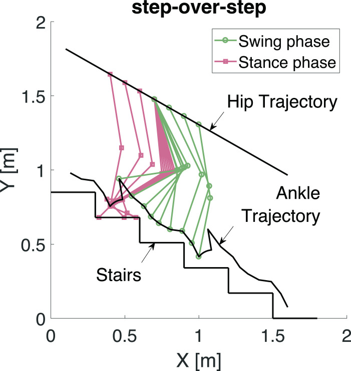
A step-over-step position reference for the ankle joint was applied (Figure 2). In order to accommodate this movement with the limitation of the UGKR of a fixed hip joint, a coordinate transformation is used. The result of this coordinate transformation is an experiment where a person is descending an escalator while it is moving upwards.19 If the descending speed of the person matches the speed of the moving escalator, this creates the illusion of a fixed hip joint while the person is still performing the motion of a stair descent.
Fig. 2.
The step-over-step stair descent trajectories in the sagittal plane (XY-plane).
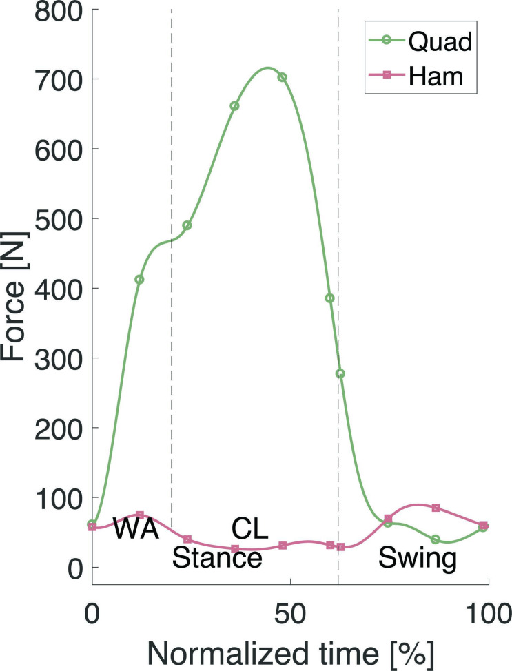
Based on measured hip, knee, and ankle joint angles and muscle forces reported in the literature,20,21 the reference trajectories for stair descent in the UGKR were defined and tested on sawbones in Chevalier et al.19 The defined quadriceps and hamstring forces were applied to the specimen to simulate the loading conditions of a stair descent manoeuvre (Figure 3). To preserve specimen integrity, a downscaling with factor four was applied to the forces compared to those reported in literature,21 resulting in the hamstring and quadriceps forces plotted in Figure 3 and the load variations in Table I.
Fig. 3.
The applied quadriceps (Quad) and hamstring (Ham) forces during the stair descent cycle. CL, controlled lowering phase; WA, weight acceptance phase.
Corresponding with Bulea et al20 and Navacchia et al,21 the stair cycle starts and ends at the heel strike (0% and 100%), which is the start of the stance phase. The end of the weight acceptance phase (WA) is at 20% and the controlled lowering (CL) phase starts where the standing leg is starting to bend. The toe off is the start of the swing phase and takes place at 62%.
As in previous kinematic studies in the UGKR,22 the kinematic calculations are based on the framework of Grood and Suntay,23 allowing for evaluation in six degrees of freedom: knee flexion angle (FA), varus/valgus rotation (VV), internal/external rotation (IE), mediolateral translation (ML), anteroposterior translation (AP), and compression/distraction (CD). In addition to Grood and Suntay,23 the three translations are separately calculated for both the medial and lateral compartments of the knee. A mean value of both compartments is also calculated. The knee kinematics (AP, ML, and CD translations, and IE, VV, and FA rotations) were assessed in real time to an accuracy of 1.0 mm/1.2°.24 This assessment is done by comparing the gold standard with the real-time method used in this work. The gold standard is performing CT scanning after the markers are connected to the bone. This does not allow the user to have real-time data of the kinematics, but only obtain kinematic results after processing. The real-time method allows for direct calculations of the knee joint kinematics during the application of the movements in the knee rig. For each degree of freedom, the mean root mean square (RMS) difference between both measurement methods has been evaluated, as described in Verstraete et al.24
Statistical analysis
Each experiment was repeated two times and subsequently the mean value was determined and interpolated with 2% increments of the stair cycle without exclusion criteria. The neutral kinematics (i.e. without external VV- or IE-load at the ankle holder) were used to evaluate the VV and IE rotation and ML, AP, and CD translations. A VV-laxity width and IE-laxity width can be defined using the kinematic patterns under external loading conditions. The VV-laxity width can be obtained by subtracting the VV alignment with a varus load on the knee joint from the VV alignment with a valgus load on the knee joint. The same was done for the IE-laxity. The kinematics after TKA were compared to the native kinematics before TKA using paired Wilcoxon signed-rank tests (Matlab; MathWorks, USA). Throughout, a significance level of 0.05 was adopted. Based on Häberli et al,25 a mean increase in translations (AP, CD, and ML) of 1.4 mm with a deviation of three times as much (4.2 mm) was expected to give clinically meaningful results. The power analysis then indicated a minimum sample size of seven cadavers under a level of significance α = 0.05 and a power 1-β = 0.8. In order to be more conservative (power > 80%), a sample size of ten seemed appropriate.
Results
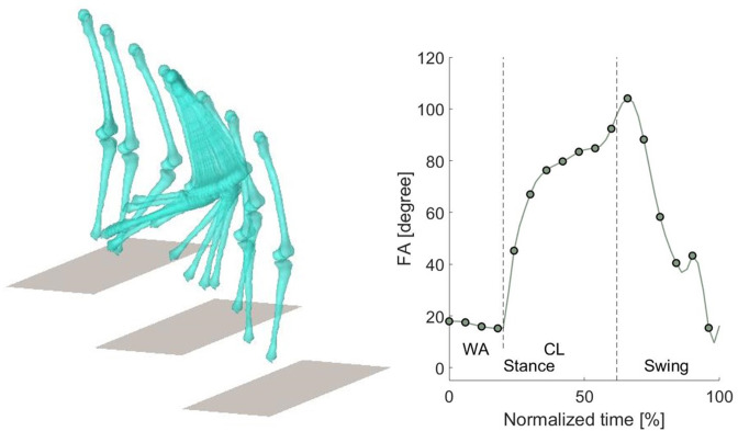
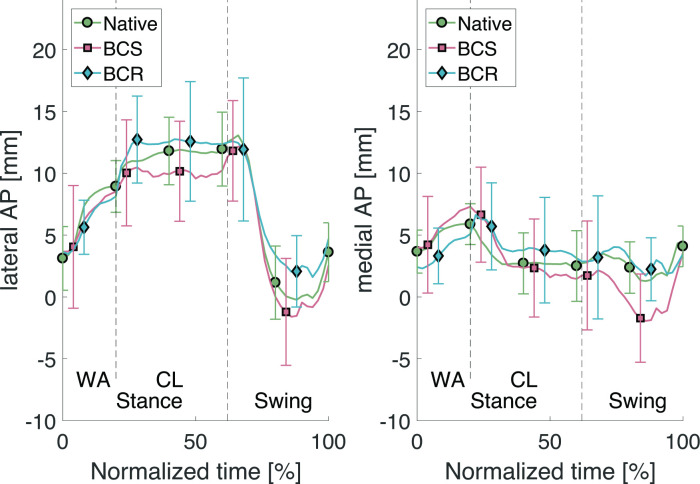
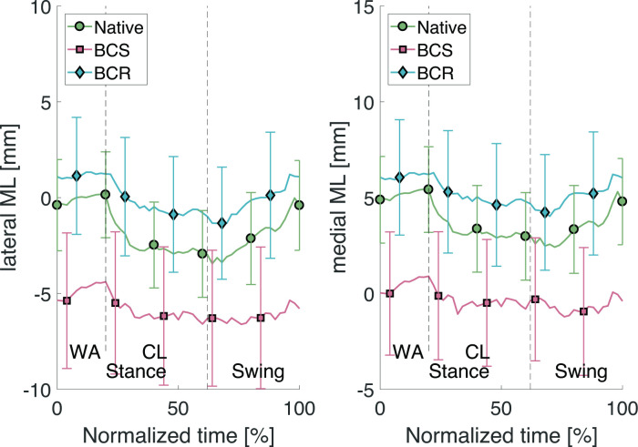
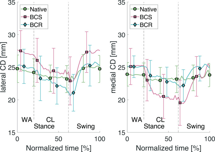
Visualization of the registered bone surfaces during stair descent was achieved using code developed in-house using the Matlab language; the measured knee flexion angle is shown in Figure 4. The resulting rotations and translations based on the neutral kinematics are reported in Table II. Note here that the rotations and translations given are those of a femur with a fixed tibia. The mean value and standard deviation (SD) are given for each phase of the stair descent: weight acceptance (WA), controlled lowering (CL), and swing (SW). The presented results for the native kinematics are the mean of all 20 specimens. The results for the kinematics with the BCS implant and the BCR implant are the mean of all ten specimens. For the AP translations, the mean evolution through the stair descent cycle is given in Figure 5. The same is presented in Figure 6 for the ML translations and Figure 7 for the CD translations. The mean kinematics for all the BCS implants are compared to the mean kinematics of all native knee joints. A second comparison is between the BCR implant and the native, and the third comparison is between the BCS implant and the BCR implant. The results show that for the BCR implant, there were more cases without significant difference between the kinematics of the implant and those of the native knee joint. Table II shows that the BCR implant mimics the native condition the best during the swing phase and for the IE rotation, AP translation, and CD translation. Furthermore, during the WA phase the BCR implant is found to resemble native kinematics for IE rotation and AP-translation on the lateral side. During the CL phase the BCR implant approximates the native condition for the IE rotation, the medial AP translation, and the medial CD translation. This is confirmed in Figures 5 to 7, where the differences between BCR and BCS compared to native kinematics are demonstrated.
Fig. 4.
Stair descent visualization of the 3D models and the flexion angle (FA) through the stair cycle averaged over all specimens. Dashed lines in the graph represent the beginning and end of different phases of the stair descent. CL, controlled lowering phase; WA, weight acceptance phase.
Table II.
Results for varus-valgus and internal-external rotation, and mediolateral, anteroposterior, and compression-distraction translation with varus < 0, valgus > 0, external < 0, internal > 0, lateral < 0, medial > 0, anterior < 0, posterior > 0, compression < 0, and distraction > 0.
| Variable | Mean (SD) | p-value* | |||||||
|---|---|---|---|---|---|---|---|---|---|
| Stance | Swing | Native | BCS | ||||||
| WA | CL | WA | CL | Swing | WA | CL | Swing | ||
| VV rotation, ° | |||||||||
| Native (n = 20) | -1.2 (0.3) | -2.6 (0.8) | -2.7 (1.4) | - | - | - | |||
| BCS (n = 10) | -2.9 (0.3) | -6.5 (1.1) | -5.8 (1.8) | < 0.05 | < 0.05 | < 0.05 | - | - | - |
| BCR (n = 10) | -0.2 (0.2) | -1.3 (0.9) | -1.3 (1.3) | < 0.05 | < 0.05 | < 0.05 | < 0.05 | < 0.05 | < 0.05 |
| IE rotation, ° | |||||||||
| Native (n = 20) | -1.6 (2.0) | -8.0 (1.6) | -0.1 (5.6) | - | - | - | |||
| BCS (n = 10) | 0.1 (0.9) | -5.9 (1.9) | -1.6 (4.8) | 0.003 | < 0.05 | 0.029 | - | - | - |
| BCR (n = 10) | -2.1 (1.1) | -7.5 (1.6) | -1.2 (4.7) | 0.465 | 0.3478 | 0.066 | < 0.05 | < 0.05 | 0.084 |
| Medial ML, (mm) | |||||||||
| Native (n = 20) | 5.2 (0.4) | 3.2 (0.7) | 3.4 (1.3) | - | - | - | |||
| BCS (n = 10) | 0.5 (0.6) | -0.4 (0.9) | -0.7 (0.8) | < 0.05 | < 0.05 | < 0.05 | - | - | - |
| BCR (n = 10) | 6.1 (0.3) | 5.0 (0.8) | 5.1 (1.1) | < 0.05 | < 0.05 | < 0.05 | < 0.05 | < 0.05 | < 0.05 |
| Lateral ML, (mm) | |||||||||
| Native (n = 20) | -0.1 (0.5) | -2.4 (0.8) | -2.0 (1.4) | - | - | - | |||
| BCS (n = 10) | -4.8 (0.6) | -6.0 (0.9) | -6.2 (0.8) | < 0.05 | < 0.05 | < 0.05 | - | - | - |
| BCR (n = 10) | 1.2 (0.3) | -0.4 (0.8) | -0.2 (1.2) | < 0.05 | < 0.05 | < 0.05 | < 0.05 | < 0.05 | < 0.05 |
| Medial AP, (mm) | |||||||||
| Native (n = 20) | 5.0 (0.9) | 3.0 (1.5) | 2.6 (2.9) | - | - | - | |||
| BCS (n = 10) | 5.7 (1.3) | 3.0 (2.5) | 0.3 (3.3) | < 0.05 | < 0.05 | < 0.05 | - | - | - |
| BCR (n = 10) | 3.6 (1.1) | 4.2 (2.0) | 2.9 (3.2) | < 0.05 | 0.069 | 0.064 | < 0.05 | < 0.05 | < 0.05 |
| Lateral AP, (mm) | |||||||||
| Native (n = 20) | 6.8 (2.4) | 11.5 (1.6) | 4.1 (5.4) | - | - | - | |||
| BCS (n = 10) | 6.3 (1.9) | 10.0 (1.8) | 3.2 (5.4) | 0.0186 | < 0.05 | 0.001 | - | - | - |
| BCR (n = 10) | 6.0 (1.9) | 12.3 (2.4) | 5.3 (5.0) | 0.068 | 0.061 | 0.081 | < 0.05 | < 0.05 | < 0.05 |
| Medial CD, (mm) | |||||||||
| Native (n = 20) | 25.5 (0.2) | 24.5 (1.0) | 24.9 (1.6) | - | - | - | |||
| BCS (n = 10) | 25.2 (0.3) | 21.0 (1.5) | 22.5 (2.3) | < 0.05 | < 0.05 | 0.0641 | - | - | - |
| BCR (n = 10) | 25.1 (0.3) | 23.4 (1.3) | 24.2 (2.1) | < 0.05 | 0.339 | 0.113 | 0.005 | < 0.05 | < 0.05 |
| Lateral CD, (mm) | |||||||||
| Native (n = 20) | 24.4 (0.4) | 23.5 (1.0) | 24.5 (1.7) | - | - | - | |||
| BCS (n = 10) | 27.2 (0.4) | 24.7 (1.3) | 26.0 (2.3) | < 0.05 | < 0.05 | < 0.05 | - | - | - |
| BCR (n = 10) | 25.1 (0.3) | 22.7 (1.3) | 24.1 (2.3) | < 0.05 | < 0.05 | 0.748 | < 0.05 | < 0.05 | < 0.05 |
Wilcoxon signed-rank test.
AP, anteroposterior; BCR, bi-cruciate retaining; BCS, bi-cruciate stabilized; CD, compression-distraction; CL, controlled lowering phase; IE, internal-external; ML, mediolateral; SD, standard deviation; VV, varus-valgus; WA, weight acceptance phase.
Fig. 5.
Lateral and medial anteroposterior (AP) translations through the stair descent cycle. BCR, bi-cruciate retaining; BCS, bi-cruciate stabilized; CL, controlled lowering phase; WA, weight acceptance phase.
Fig. 6.
Lateral and medial mediolateral (ML) translations through the stair descent cycle. BCR, bi-cruciate retaining; BCS, bi-cruciate stabilized; CL, controlled lowering phase; WA, weight acceptance phase.
Fig. 7.
Lateral and medial compression-distraction (CD) translations through the stair descent cycle. BCR, bi-cruciate retaining; BCS, bi-cruciate stabilized; CL, controlled lowering phase; WA, weight acceptance phase.
VV laxity and IE laxity
The VV laxity and IE laxity values averaged over all specimens are shown in Table III. No values are reported during the swing phase, as no VV/IE load on the knee joint occurs during this phase due to lack of contact with the ground. The average VV laxity and IE laxity over all specimens throughout the stair cycle is shown in Figure 8. This test concluded that the laxity envelopes for varus-valgus are significantly different for both implant types compared to the native laxity. For the IE laxity, there is no significant difference between the laxity of the implanted specimens and the native specimens during the CL phase.
Table III.
Results for varus-valgus and internal-external laxity width during the stair descent cycle.
| Type | Mean (SD) | p-value* | |||||
|---|---|---|---|---|---|---|---|
| Stance | Swing | Native | BCS | ||||
| WA | CL | WA | CL | WA | CL | ||
| VV laxity, ° | |||||||
| Native (n = 20) | 4.1 (0.7) | 2.9 (0.5) | - | - | - | ||
| BCS (n = 10) | 4.3 (0.6) | 3.8 (0.7) | - | 0.010 | < 0.05 | - | - |
| BCR (n = 10) | 3.7 (0.6) | 3.3 (0.5) | - | < 0.05 | < 0.05 | < 0.05 | < 0.05 |
| IE laxity, ° | |||||||
| Native (n = 20) | 9.1 (1.6) | 12.2 (1.7) | - | - | - | ||
| BCS (n = 10) | 10.4 (0.8) | 12.2 (1.6) | - | < 0.05 | 0.476 | - | - |
| BCR (n = 10) | 12.0 (1.1) | 13.7 (1.9) | - | < 0.05 | 0.079 | < 0.05 | < 0.05 |
Paired Wilcoxon signed-rank test.
BCR, bi-cruciate retaining; BCS, bi-cruciate stabilized; CL, controlled lowering phase; IE, internal-external; SD, standard deviation; VV, varus-valgus; WA, weight acceptance phase.
Fig. 8.
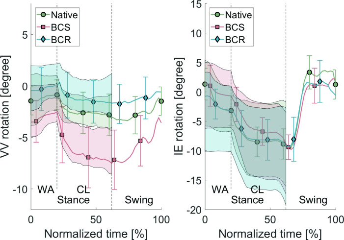
Varus-valgus (VV) laxity and internal-external (IE) laxity averaged over all specimens with varus < 0, valgus > 0, external < 0, internal > 0 during the stair descent cycle. The line plot represents the kinematics without external loads. The top of the shaded areas represents the condition with valgus/internal load, and the bottom of the shaded area represents the condition with varus/external load. The bars represent the 95% confidence intervals. BCR, bi-cruciate retaining; BCS, bi-cruciate stabilized; CL, controlled lowering phase; WA, weight acceptance phase.
The VV laxity width remains approximately constant during the stance phase. During the WA phase, the VV rotations remain relatively constant, while during the CL phase there is a clear shift of the rotations resulting from the knee flexion. The IE laxity width increases during the CL phase (Figure 8). During the swing phase, the neutral kinematics return to the initial values of the WA phase.
Discussion
The goal of this study was to impose a stair descent on native and implanted specimens while measuring the tibiofemoral kinematics in the UGent Knee Rig. During this process, physiological flexor and extensor loads are applied on the knee joint for each measurement. To assess the laxity of the knee joint, additional varus/valgus loads and internal/external loads were applied on the knee joint.
To the authors’ knowledge, only one article has focused on evaluating knee kinematics during stair descent for different types of knee implants in an in vitro study.10 In vitro studies have the advantage of being able to measure native kinematics alongside TKA kinematics compared to in vivo fluoroscopy tests. The posterior shift of the femur when applying the quadriceps force during the stance phase, shown in Borque et al,10 was confirmed during this experiment, seen in the clear increase of the lateral AP (Table II) during the CL phase where the quadriceps is exerting maximum force and the person is standing on one flexed leg. This increase compared to the WA phase indicates a posterior shift. For both implants (BCS and BCR) the femur shifted anteriorly in the end of the swing phase (Figure 5), i.e. just before WA, which is also concluded in Borque et al.10 The major limitation of their study is mitigated in the research here, as the full stair descent can be simulated, allowing for conclusions in all phases. From Figure 5 and the p-values in Table II, it can also be concluded that during all phases of the stair descent, the BCR implant mimics the native condition more accurately than the BCS implant for the AP translations. Figure 5 shows that retaining the cruciate ligaments allows the knee joint to shift more posteriorly during the controlled lowering phase.
For the ML translations, Figure 6 shows that the BCR implant approximates the native condition better throughout the entire range of the stair descent cycle than the BCS implant. However, the p-values listed in Table II indicate that there is still a significant difference between the kinematics of the native knee joint and those of the BCR implant.
The data for the average CD show a clear decrease in joint distraction during the CL phase (Table II). This is deemed natural as this is a one-legged phase where the entire body weight (i.e. high quadriceps force to balance this weight) is placed on one leg.
For the BCS implant, an increased distraction was found on the lateral side (Figure 7). This increase in distraction was not present for the BCR implant. This can be understood as a result of the surgical act to reach a good stability in the knee joint after removing the cruciate ligaments in the BCS (i.e. gap balancing) and substituting it by a femoral-insert-baseplate volume that surpasses the bone resection.26 This problem is mitigated in the BCR implant without using conforming geometry in the implant design. The increased distraction is in line with previous research.27
For IE rotation, there was a clear increase in internal rotation during the stance phase (Figure 8) for the BCS implant. Here, the post-cam mechanism restricts the external rotation, a finding which is also found in literature.28 The p-values in Table II indicate no significant difference between the BCR implant and the native kinematics.
For the VV rotation, Figure 8 shows that the BCR implant again mimics the native condition more accurately than the BCS implant. However, the p-values in Table II show that there is still a significant difference between the BCR implant and the native kinematics.
The current study has limitations and therefore one must be cautious with the conclusions. A potential weakness includes the fact that the quadriceps force is applied as one unit instead of its four separate heads. However, the hamstrings are considered as two units with a medial and a lateral component. Also, scaled-down muscle loading profiles are used to assure the integrity of the ligament fibres rather than the real forces that occur in live patients, so comparison with in vivo measurements may be difficult. A strong point of the current study is choice of the Journey II series, which have similar geometries to the femoral components for the different implants and relatively similar geometries to the inserts.17 Therefore, the effect of articular geometry on the kinematics is avoided as much as possible.29 Furthermore, all operations on the cadavers were performed by the same trained surgeon (HV) in order to minimize differences in surgical technique.
The conclusion of this study is that the UGent Knee Rig is capable of simulating a stair descent on knee specimens. The test protocol allows for tibiofemoral knee kinematics in native and implanted specimens. The kinematic analysis shows that for the IE rotation and the lateral AP translation, the BCR implant approximates native kinematics better during all phases of the stair descent compared to the BCS implant. The kinematic results show that the difference between the kinematics of the BCR implant and the native kinematics is smaller compared to the BCS knee implant for VV rotation and ML translation. However, statistical analysis shows that there is still a significant difference in these directions. The results show that the BCR knee implant has the potential to better approximate the native kinematics compared to the BCS knee implant in certain directions. Whether this will result in better patient outcomes remains to be investigated.
Author contributions
A. Chevalier: Conceptualization, Investigation, Writing – original draft, Methodology.
H. Vermue: Investigation, Methodology, Writing – review & editing.
L. Pringels: Investigation, Methodology, Writing – review & editing.
S. Herregodts: Methodology, Writing – review & editing.
K. Duquesne: Investigation, Writing – review & editing.
J. Victor: Writing – review & editing, Resources.
M. Loccufier: Writing – review & editing.
Funding statement
The authors disclose receipt of the following financial or material support for the research, authorship, and/or publication of this article: the financial support of Smith & Nephew through an unrestricted research grant.
ICMJE COI statement
H. Vermue acknowledges a grant from Research Foundation Flanders, Belgium as Aspirant FWO (Grant 11F5919N).
Data sharing
The datasets generated and analyzed in the current study are not publicly available due to data protection regulations. Access to data is limited to the researchers who have obtained permission for data processing. Further inquiries can be made to the corresponding author.
Ethical review statement
This study was approved by the institutional review board (IRB) by the University of Ghent ethical committee (B 670201421989), and was performed in accordance with the 1964 Helsinki Declaration and its amendments.
© 2023 Author(s) et al.This is an open-access article distributed under the terms of the Creative Commons Attribution Non-Commercial No Derivatives (CC BY-NC-ND 4.0) licence, which permits the copying and redistribution of the work only, and provided the original author and source are credited. See https://creativecommons.org/licenses/by-nc-nd/4.0/
Contributor Information
Amelie Chevalier, Email: amelie.chevalier@uantwerpen.be.
Hannes Vermue, Email: hannes.vermue@ugent.be.
Lauren Pringels, Email: lauren.pringels@ugent.be.
Stijn Herregodts, Email: stijn.herregodts@ugent.be.
Kate Duquesne, Email: kate.duquesne@ugent.be.
Jan Victor, Email: jan.victor@ugent.be.
Mia Loccufier, Email: mia.loccufier@ugent.be.
References
- 1. Evans JT, Walker RW, Evans JP, Blom AW, Sayers A, Whitehouse MR. How long does a knee replacement last? A systematic review and meta-analysis of case series and national registry reports with more than 15 years of follow-up. Lancet. 2019;393(10172):655–663. doi: 10.1016/S0140-6736(18)32531-5. [DOI] [PMC free article] [PubMed] [Google Scholar]
- 2. Tran T, McEwen P, Peng Y, et al. Kinematic alignment in total knee arthroplasty: a five-year prospective, multicentre, survivorship study. Bone Jt Open. 2022;3(8):656–665. doi: 10.1302/2633-1462.38.BJO-2021-0214.R1. [DOI] [PMC free article] [PubMed] [Google Scholar]
- 3. Sharkey PF, Lichstein PM, Shen C, Tokarski AT, Parvizi J. Why are total knee arthroplasties failing today--has anything changed after 10 years? J Arthroplasty. 2014;29(9):1774–1778. doi: 10.1016/j.arth.2013.07.024. [DOI] [PubMed] [Google Scholar]
- 4. Van Onsem S, Verstraete M, Van Eenoo W, Van Der Straeten C, Victor J. Are TKA kinematics during closed kinetic chain exercises associated with patient-reported outcomes? A preliminary analysis. Clin Orthop Relat Res. 2020;478(2):255–263. doi: 10.1097/CORR.0000000000000991. [DOI] [PMC free article] [PubMed] [Google Scholar]
- 5. Wang Y, Yin M, Zhu S, Chen X, Zhou H, Qian W. Patient-reported outcome measures used in patients undergoing total knee arthroplasty. Bone Joint Res. 2021;10(3):203–217. doi: 10.1302/2046-3758.103.BJR-2020-0268.R1. [DOI] [PMC free article] [PubMed] [Google Scholar]
- 6. Greene KA, Schurman JR. Quadriceps muscle function in primary total knee arthroplasty. J Arthroplasty. 2008;23(7 Suppl):15–19. doi: 10.1016/j.arth.2008.06.014. [DOI] [PubMed] [Google Scholar]
- 7. Scott G, Imam MA, Eifert A, et al. Can a total knee arthroplasty be both rotationally unconstrained and anteroposteriorly stabilised? A pulsed fluoroscopic investigation. Bone Joint Res. 2016;5(3):80–86. doi: 10.1302/2046-3758.53.2000621. [DOI] [PMC free article] [PubMed] [Google Scholar]
- 8. Taylor WR, Schütz P, Bergmann G, et al. A comprehensive assessment of the musculoskeletal system: The CAMS-Knee data set. J Biomech. 2017;65:32–39. doi: 10.1016/j.jbiomech.2017.09.022. [DOI] [PubMed] [Google Scholar]
- 9. Gray HA, Guan S, Young TJ, Dowsey MM, Choong PF, Pandy MG. Comparison of posterior-stabilized, cruciate-retaining, and medial-stabilized knee implant motion during gait. J Orthop Res. 2020;38(8):1753–1768. doi: 10.1002/jor.24613. [DOI] [PubMed] [Google Scholar]
- 10. Borque KA, Gold JE, Incavo SJ, Patel RM, Ismaily SE, Noble PC. Anteroposterior knee stability during stair descent. J Arthroplasty. 2015;30(6):1068–1072. doi: 10.1016/j.arth.2015.01.011. [DOI] [PubMed] [Google Scholar]
- 11. Verstraete MA, Victor J. Possibilities and limitations of novel in-vitro knee simulator. J Biomech. 2015;48(12):3377–3382. doi: 10.1016/j.jbiomech.2015.06.007. [DOI] [PubMed] [Google Scholar]
- 12. Chevalier A, Verstraete M, Ionescu C, De Keyser R. Decoupled control for the bicycling UGent knee rig: design, implementation, and validation. IEEE/ASME Trans Mechatron. 2017;22(4):1685–1694. doi: 10.1109/TMECH.2017.2696708. [DOI] [Google Scholar]
- 13. King SL, Underdown T, Reeves ND, Baltzopoulos V, Maganaris CN. Alternate stair descent strategies for reducing joint moment demands in older individuals. J Biomech. 2018;78:126–133. doi: 10.1016/j.jbiomech.2018.07.029. [DOI] [PubMed] [Google Scholar]
- 14. Mugnai R, Digennaro V, Ensini A, Leardini A, Catani F. Can TKA design affect the clinical outcome? Comparison between two guided-motion systems. Knee Surg Sports Traumatol Arthrosc. 2014;22(3):581–589. doi: 10.1007/s00167-013-2509-9. [DOI] [PubMed] [Google Scholar]
- 15. Arnout N, Verstraete M, Victor J, Bellemans J, Tampere T, Chevalier A. The contralateral knee is a good predictor for determining normal knee stability: a cadaveric study. Knee Surg Sports Traumatol Arthrosc. 2022;30(4):1316–1324. doi: 10.1007/s00167-021-06575-y. [DOI] [PubMed] [Google Scholar]
- 16. World Medical Association World Medical Association Declaration of Helsinki: ethical principles for medical research involving human subjects. JAMA. 2013;310(20):2191–2194. doi: 10.1001/jama.2013.281053. [DOI] [PubMed] [Google Scholar]
- 17. Verstraete MA, Willemot L, Van Onsem S, Stevens C, Arnout N, Victor J. 3D printed guides for controlled alignment in biomechanics tests. J Biomech. 2016;49(3):484–487. doi: 10.1016/j.jbiomech.2015.12.036. [DOI] [PubMed] [Google Scholar]
- 18. Arnout N, Victor J, Chevalier A, Bellemans J, Verstraete MA. Muscle loaded stability reflects ligament-based stability in TKA: a cadaveric study. Knee Surg Sports Traumatol Arthrosc. 2022;30(2):612–620. doi: 10.1007/s00167-020-06329-2. [DOI] [PubMed] [Google Scholar]
- 19. Chevalier A, Victor J, Herregodts S, Loccufier M. Descending staircase in the UGent knee rig: a feasibility study. IFAC-PapersOnLine. 2021;54(15):430–435. doi: 10.1016/j.ifacol.2021.10.294. [DOI] [Google Scholar]
- 20. Bulea TC, Kobetic R, Audu ML, Schnellenberger JR, Pinault G, Triolo RJ. Forward stair descent with hybrid neuroprosthesis after paralysis: Single case study demonstrating feasibility. J Rehabil Res Dev. 2014;51(7):1077–1094. doi: 10.1682/JRRD.2013.12.0257. [DOI] [PMC free article] [PubMed] [Google Scholar]
- 21. Navacchia A, Rullkoetter PJ, Schütz P, List RB, Fitzpatrick CK, Shelburne KB. Subject-specific modeling of muscle force and knee contact in total knee arthroplasty. J Orthop Res. 2016;34(9):1576–1587. doi: 10.1002/jor.23171. [DOI] [PMC free article] [PubMed] [Google Scholar]
- 22. Arnout N, Victor J, Vermue H, Pringels L, Bellemans J, Verstraete MA. Knee joint laxity is restored in a bi-cruciate retaining TKA-design. Knee Surg Sports Traumatol Arthrosc. 2020;28(9):2863–2871. doi: 10.1007/s00167-019-05639-4. [DOI] [PubMed] [Google Scholar]
- 23. Grood ES, Suntay WJ. A joint coordinate system for the clinical description of three-dimensional motions: application to the knee. J Biomech Eng. 1983;105(2):136–144. doi: 10.1115/1.3138397. [DOI] [PubMed] [Google Scholar]
- 24. Verstraete M, Arnout N, Vancouillie T, De Baets P, Victor J. Computed tomography based real-time joint kinematics during in-vitro tests. EPiC Series in Health Sciences. 2017;1:369–374. [Google Scholar]
- 25. Häberli J, Henle P, Acklin YP, Zderic I, Gueorguiev B. Knee joint kinematics with dynamic augmentation of primary anterior cruciate ligament repair - a biomechanical study. J Exp Orthop. 2016;3(1):29. doi: 10.1186/s40634-016-0064-2. [DOI] [PMC free article] [PubMed] [Google Scholar]
- 26. Crottet D, Kowal J, Sarfert SA, et al. Ligament balancing in TKA: evaluation of a force-sensing device and the influence of patellar eversion and ligament release. J Biomech. 2007;40(8):1709–1715. doi: 10.1016/j.jbiomech.2006.08.004. [DOI] [PubMed] [Google Scholar]
- 27. Schnurr C, Eysel P, König DP. Is the effect of a posterior cruciate ligament resection in total knee arthroplasty predictable? Int Orthop. 2012;36(1):83–88. doi: 10.1007/s00264-011-1295-6. [DOI] [PMC free article] [PubMed] [Google Scholar]
- 28. McAuley JP, Engh GA. Constraint in total knee arthroplasty: when and what? J Arthroplasty. 2003;18(3 Suppl 1):51–54. doi: 10.1054/arth.2003.50103. [DOI] [PubMed] [Google Scholar]
- 29. Hashemi J, Chandrashekar N, Gill B, et al. The geometry of the tibial plateau and its influence on the biomechanics of the tibiofemoral joint. J Bone Joint Surg Am. 2008;90-A(12):2724–2734. doi: 10.2106/JBJS.G.01358. [DOI] [PMC free article] [PubMed] [Google Scholar]


