Background:
Multiple screw-in attempts under fluoroscopy are often needed to place the pacing lead tip near or at the left bundle branch (LBB). This study was conducted to evaluate the feasibility of implanting an LBB pacing lead in the proximal LBB (PLBB) guided by intracardiac echocardiography (ICE).
Methods:
The distribution of the LBB was initially determined by ICE anatomic imaging and 3-dimensional electrical mapping of His and LBB potentials in 20 patients in the first parts of the study. In the second part, 101 consecutive pacemaker-indicated patients were randomized into the ICE-guided and non-ICE groups for LBB pacing implantation. The procedural details and electrophysiological characteristics of the 2 groups were compared.
Results:
In the first part of the study, PLBB was identified at 10 to 20 mm from the tricuspid annulus toward the apex with an area of 4.5±1.1 cm2. In the second part, the number of lead screw-in attempts in the septum was fewer in the ICE group than in the non-ICE group (1.43±0.62 versus 1.98±0.75, P=0.0002). The duration of the procedure (26±8 versus 43±9 minutes, P<0.001) and fluoroscopy for LBB pacing implantation (7.4±1.8 versus 10.7±2.4 minutes, P<0.001) in the ICE group was significantly shorter than those in the non-ICE group. LBB pacing in the ICE group generated a lesser QRS duration with more cases of LBB trunk pacing (46.8% versus 25%, P=0.031) and PLBB (91.5% versus 72.7%, P=0.0267) pacing compared with that in the non-ICE group.
Conclusions:
The basal left ventricular septum can be better visualized using ICE. ICE-guided PLBB pacing is feasible and safe, with a shorter duration required for the procedure and fluoroscopy, and generates greater LBB trunk pacing and PLBB pacing.
Keywords: bradycardia, cardiac conduction system, catheters, endocardium, fluoroscopy
What is Known?
The distribution of the left bundle branch (LBB) can be determined by 3-dimensional electrical mapping of LBB potentials in human heart.
When the pacing site is at proximal LBB, the paced ECG shows right bundle branch block morphology and its R-wave progression at lead V2 through V6 is not later than the QRS complex during normal sinus rhythm. However, pacing at LBB fascicular branch causes shifted electrical vector in 12-lead ECG.
What the Study Adds
The study explores the implantation process of proximal LBB pacing guided by intracardiac echocardiography.
The basal left ventricular septum can be better visualized using intracardiac echocardiography, and the pacing lead tip can be reliably placed at the proximal LBB with paced QRS vector similar to that during normal sinus rhythm.
Intracardiac echocardiography–guided implantation of proximal LBB pacing uses less fluoroscopy time and procedure time, demonstrating procedural feasibility, and safety.
See Editorial by Batul and Vijayaraman
His bundle pacing, which uses the native cardiac conduction system, is a physiological pacing modality and has shown clinical benefits in patients with bradycardia or cardiac failure.1 However, His bundle pacing is associated with several limitations, such as difficult implantation procedure, high capture thresholds, low R-wave amplitude, atrial oversensing, and a higher risk of lead revision owing to late threshold increase.2 Left bundle branch pacing (LBBP) has proved to be a promising alternative to His bundle pacing for achieving physiological pacing. It maintains antegrade activation of the left fascicular system and often generates a relatively narrow QRS complex.3 The LBB appearance beneath the endocardium at the angle formed by the noncoronary and right coronary aortic cusps. After a short path left bundle trunk gives rise to its 2 main fascicles: the anterior and the posterior divisions. Anterior and posterior fascicles has a diffuse fan-like structure widely distributed beneath the left septal surface,4 which makes it, particularly the distal LBB, an easy target for conduction system pacing. However, placing the pacing lead tip close to the trunk (proximal) LBB, where pacing is more physiological than that at the distal LBB, remains a challenge frequently encountered in the process. In this study, we explore the feasibility of implanting LBBP lead under the guidance of intracardiac echocardiography (ICE) to capture the proximal section of the LBB, a technique that is used to not only reduce the fluoroscopy duration for implantation but also improve the accuracy of LBBP lead placement at an optimal position. The study aimed to assess the safety and efficacy of this novel method of ICE-guided LBBP and compare them with those of regular non-ICE guided LBBP lead placement under fluoroscopic imaging.
Methods
The data, analytic methods, and study materials will be made available to other researchers for purposes of reproducing the results or replicating the procedure.
Study Design and Patient Selection
The study was prospectively conducted in 2 parts. In the first part, the distribution area of the LBB was examined using ICE in conjunction with 3-dimensional (3D) electrical mapping. In the second part, LBBP implantation was performed using ICE guidance (ICE group) or the conventional non-ICE guided method (non-ICE group). Patients in the second part of the study were randomized into the ICE or non-ICE groups.
In part one, patients were candidates for ablation procedures in whom cardiac anatomic markers were mapped with a mapping catheter and ICE. In part 2, consecutive patients were referred for cardiac pacing therapy for bradycardia indications, based on current American Heart Association/American College of Cardiology/Heart Rhythm Society clinical practice guidelines,5 and were enrolled at the First People’s Hospital of Yunnan Province in China from May 1, 2019 to May 1, 2020. Patients with indications for cardiac resynchronization therapy or implantable cardioverter defibrillator implantation were excluded. All patients in the study provided signed forms for written informed consent agreeing to the implantation procedure, and the study procedure was approved by the hospital’s institutional review board and registered in China Clinical Trial (ChiCTR1900022908; https://www.chictr.org.cn/edit.aspx?pid=38631&htm=4).
Part 1: Distribution of LBB Determined Using ICE With the Assistance of 3D Electrical Mapping
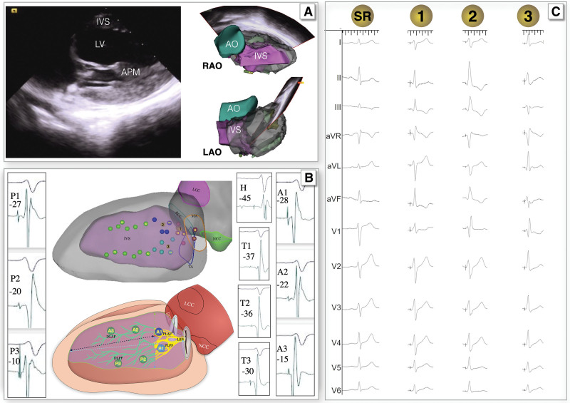
The cardiac conductive system, including the His bundle and LBB, was mapped with 3D electroanatomic mapping (CARTO Biosense Webster Inc, Diamond Bar, CA) in 20 patients without structural heart disease or bundle branch block. These patients underwent radiofrequency ablation for premature ventricular contractions originating from the left ventricular papillary muscle. A 10Fr ICE probe (Soundstar, Biosense Webster, Inc, CA) was placed in the right or left femoral vein and advanced to the middle of the right atrium or right ventricle (RV). ICE was used to construct a 3D anatomical model of the cardiac chambers, as described in previous studies.6 Briefly, ICE was used to reconstruct the left ventricle (LV), ventricular septum, papillary muscle, aortic sinus, mitral valve annulus (MA), and tricuspid valve annulus (TA). Following this, a 4 mm, 4-pole cool saline-irrigated catheter (Thermo-cool, Biosense Webster Inc; Diamond Bar) compatible with the CARTO system (CARTO, Biosense-Webster Inc, Diamond Bar) was introduced into the LV using a retrograde approach from the femoral artery for activation mapping based on the ICE-reconstructed ventricular model. The potentials of the His bundle and LBB were mapped using a saline-irrigated catheter on the left ventricular septum and marked in the ventricular model developed using ICE (Figure 1). The classification of the pacing site was based on the previously described ECG characteristics of the left bundle fascicular block and fascicular originated ventricular arrhythmia,7,8 and the paced ECG met the criteria of LBB capture.9,10 Proximal LBB (PLBB) pacing involves LBB trunk pacing,10 proximal left anterior fascicle pacing, and proximal left posterior fascicle pacing. When the pacing site is at PLBB, the ECG shows right bundle branch delay morphology and its R-wave progression at lead V2 through V6 is not later than sinus rhythm. LBB trunk pacing shares similar QRS morphology with sinus rhythm. When ECG shows left anterior fascicle block it indicates proximal left posterior fascicle pacing, when ECG shows left posterior fascicle block it indicates proximal left anterior fascicle pacing (Figure 1). Information on this location in the interventricular septum (IVS) and its relationship with adjacent anatomical structures, such as the aortic sinus or MA, was used to assist the ICE probe in guiding LBBP lead placement in the second part of the study.
Figure 1.
Electroanatomic mapping of the proximal left bundle branch (PLBB). A, Three-dimensional model of the cardiac cavity mapped using intracardiac echocardiography (ICE). B, His or left bundle branch (LBB) potentials mapped using a high-density ablation catheter during sinus rhythm (upper) and sketch map (bottom)with the computer-modified image: the red dot marked H represents the distal His; the His potential to onset of QRS interval (HV interval) was 45 ms. The red dots marked T represent the trunk of the LBB, the dark blue dots marked A1 represent the proximal of left anterior fascicle, the green dots marked A2\A3 represent the distal of left anterior fascicle, the light blue dots marked P1 represent the proximal of left posterior fascicle, the green dots marked P2\P3 represent the distal of left posterior fascicle, the green line represent the distal region of the LBB, and the yellow line represent the PLBB. B also shows the relationship between the distribution area of the LBB and adjacent anatomical markers, the yellow part of LBB in the sketch map (bottom) represents the PLBB, the dotted arrow indicates the distance from a point of PLBB to the surrounding anatomical marks. C, QRS wave after the capture of the LBB after pacing at different areas (the yellow dots on B). AO indicates aorta; APM, anterior papillary muscle; LAO, left anterior oblique view; LV, left ventricular; and RAO, right anterior oblique view.
Selective LBBP, capturing only the LBB as a direct LBB capture sign, can be demonstrated with a discrete local component separate from the stimulus artifact on the unipolar electrogram from the LBBP lead.9
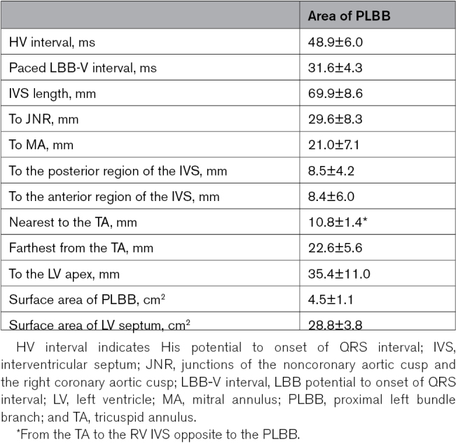
Twenty consecutive patients in the first part of the study underwent 3D mapping of the conduction system. The mean His potential to onset of QRS interval (HV interval) was 48.9±6.0 ms. When the paced ECG met the standard of LBB pacing9 and PLBB pacing, PLBB pacing was considered (Figure 1). The distribution area of the PLBB determined using 3D mapping was 4.5±1.1 cm2; the distances to anatomic markers are summarized in Table 1. At the longitudinal view of the LV, when the IVS, TA, and LV anterior papillary muscle were displayed in the same sector, the longest and shortest distances from the TA were 22.6±5.6 and 10.8±1.4 mm, respectively; when measured from the TA to the right ventricular septum contralateral to the PLBB, this area covered a region of 10 to 20 mm of the anterior RV and posterior septum as a target for the lead entry site of PLBB pacing (sketch map of Figure 1).
Table 1.
Distribution Area of the PLBB
Part 2: ICE-Guided LBBP Implantation Compared With the Conventional Procedure
One hundred and one consecutive patients with bradycardia were randomized into the ICE group (N=50) or non-ICE group (N=51) using conventional fluoroscopy. All procedures in this study were performed by implanters with experience in LBBP implantation.
An intracardiac electrogram from the lead tip and 12-lead surface ECG were simultaneously recorded at a sweep speed of 100 mm/s on a multichannel electrophysiological recorder (Bard Electrophysiology Lab System, MA). Implantation was performed using a Select Secure pacing lead (Model 3830, 69 cm; Medtronic Inc, Minneapolis, MN) delivered to the RV through a fixed-curve sheath (C315 His; Medtronic Inc).
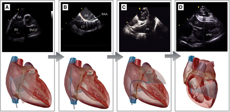
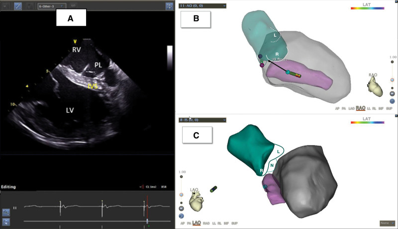
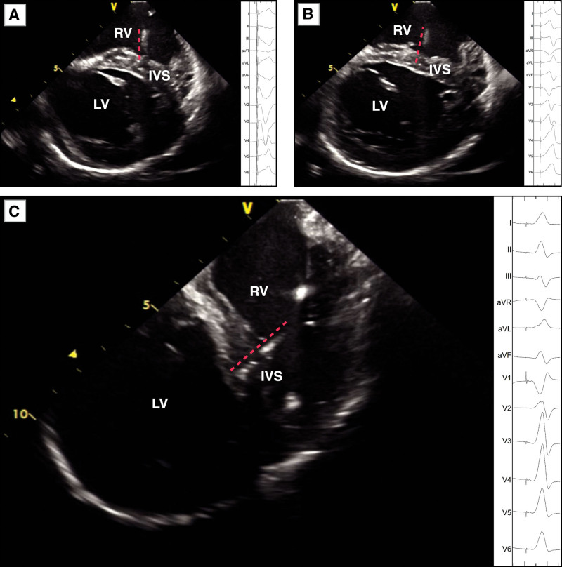
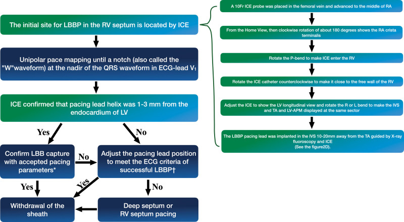
In the non-ICE group, LBBP was achieved via a trans ventricular septal approach using LBB capture criteria reported previously.11 If a successful LBBP could not be achieved after 3 attempts of lead positioning or if the duration of fluoroscopy exceeded 20 minutes, the pacing lead was placed in the deep ventricular septum or RV septum, and LBBP was considered to have failed. The ICE-guided method, based on the findings from the first part of the study for the ICE group, is described as follows (Figure 2): (1) from the home-view, a clockwise rotation by ≈180° showed the right atrial crista terminalis; (2) the P-bend was rotated to facilitate the entry of the ICE probe into the RV; (3) the ICE catheter was rotated counterclockwise to place it close to the free wall of the RV; (4) the R and L bends were adjusted to display the IVS, TA, and LV anterior papillary muscle in the same sector; (5) the LBBP lead was then implanted at 10 to 20 mm from the TA on IVS, and the pacing lead helix positioned perpendicularly against the septum was advanced to penetrate from this area to the LV subendocardium (Figure 3). The procedure of ECG assessment and lead fixation were the same as those used in the non-ICE group.2 The pacing lead helix location and the depth within the septum were assessed using ICE during implantation (Figure 4). During LBBP lead fixation into the IVS, the ICE was used to monitor whether the lead was perpendicular to the IVS and determine the thickness and scars (if present) in the IVS (Figure 5). The criteria for PLBB pacing were based on a previous report by Huang et al9 and were the same as those described in the first part of the study.
Figure 2.
Work-flow of the intracardiac echocardiography (ICE)–guided left bundle branch pacing (LBBP) procedure. The home view (A) clockwise rotation of ≈180° shows the crista terminalis (B); rotate the P-bend to make the ICE enter the right ventricle (C); rotate the ICE catheter counterclockwise to bring it close to the free wall of the right ventricle; adjust the R and L bends to display the interventricular septum (IVS), TV, and left ventricular (LV) anterior papillary muscle (APM) at the same sector (D). The upper part is the intracardiac structure shown using ICE, and the lower part is the schematic diagram of the ultrasound sector. AO indicates aorta; PA, pulmonary artery; RA, right atrium; RAA, right atrial appendage; RV, right ventricule; RVOT, right ventricular outflow tract; and TV, tricuspid valve.
Figure 3.
Implantation of the left bundle branch lead under intracardiac echocardiography (ICE) guidance. A, Pacing lead (PL) implanted in the left ventricular (LV) endocardium through the interventricular septum (IVS) under ICE guidance. B and C, Three-dimensional model of LV and aorta (AO) reconstructed using ICE. The green part denotes the aorta, L denotes the left coronary aortic cusp (LCC), N denotes the noncoronary aortic cusp (NCC), and R denotes the right coronary aortic cusp (RCC). The pink part indicates the IVS, and the gray part indicates the LV. LAO indicates left anterior oblique view; LAT, local activation time; and RAO, right anterior oblique view.
Figure 4.
Twelve-lead ECG during pacing at different parts of the interventricular septum (IVS). A through C, 12-lead ECG (right side of figure) during pacing in the right ventricular (RV) septum, middle IVS, and left bundle branch, which located by intracardiac echocardiography (ICE; left side of figure). The red dotted line indicates the pacing lead tip. LV indicates left ventricular.
Figure 5.
Flowchart of the procedure for intracardiac echocardiography (ICE)–guided left bundle branch pacing (LBBP). *Confirm LBB capture with accepted pacing parameters: (1) pace the morphology of the right bundle branch block pattern; (2) record the LBB potential from the LBBP lead; (3) stimulus-peak left ventricular (LV) activation time (LVAT) shortens abruptly with increasing output and remains the shortest and constant at low and high outputs. †The method of adjustment of the pacing lead position involves the following aspects: (1) the pacing lead helix was closer to the endocardium of the LV monitored using ICE, (2) the pacing lead is positioned perpendicular to the IVS and enters the endocardium of the LV, as monitored using ICE, (3) under ICE guidance, the pacing lead was kept away from the scar area of the IVS. (4) The LBBP lead was implanted around the original site under the guidance of ICE. APM indicates anterior papillary muscle; RA, right atrium; RV, right ventricular; and TA, tricuspid annulus.
The procedure interval and duration of fluoroscopy in the LBBP procedure were considered as the duration between the insertion of the fixed-curve sheath and the successful implantation of the LBBP lead and withdrawal of the fixed-curve sheath.
Echocardiography and Follow-Up
All patients underwent transthoracic echocardiography (TTE) at baseline and 3-month follow-up by an experienced specialist who was blinded to the study. Echocardiography (apical 3- and 4-chamber and parasternal short-axis views) was performed to assess the location and depth of the pacing lead helix in the IVS, and the IVS thickness (shortest distance) during diastole was measured at the site of the pacing lead helix. The IVS length was measured at the end of left ventricular diastolic phase in apical 4-chamber views, from TA to the endocardium of right ventricular apex. The distance of the pacing lead helix tip to the LV endocardium was measured. The distance between the electrode and TA was measured from the septal leaflet of the tricuspid valves to the entry point of the pacing lead in the RV septum in a standard 4-chamber view. Surface ECG was performed before and after the implantation and during the follow-up visit. Twelve-lead surface ECG were recorded at a speed of 25 mm/s on ECG machine at follow-up. The QRS duration was measured from the onset of intrinsic or paced QRS to the end of the longest QRS complex in all 12 leads. The pacing stimulus to LV activation time is defined as the interval from the pacing stimulus to the peak of the R wave in lead V5.9 Two independent experienced ECG specialists blinded to the conditions of the study performed the measurements. Pacing lead parameters, including the R wave amplitude, capture thresholds, and pacing impedances, were measured during the procedure and 3-month follow-up.
Statistical Analysis
Assuming an absolute increase of 30% in the incidence of LBB trunk pacing in patients in the ICE group (45%) compared with that in patients in the non-ICE group (15%) the estimated sample size per group was 46 patients to achieve 90% power with a type I error of 5%. To account for a potential dropout rate of 10%, the inclusion of 101 patients was planned. Randomization was achieved using a computerized algorithm without any restriction.
Continuous variables are presented as mean±SD if they were normally distributed or as median and interquartile range and were compared using a Student t test or Wilcoxon Mann-Whitney U test. Categorical variables are summarized as absolute and relative frequencies and were analyzed using the χ2 test or Fisher exact test as appropriate. Differences with P<0.05 were considered statistically significant. Analyses were performed using SPSS version 19.0 (IBM Corporation, Armonk, NY) by an independent statistician.
Results
Patient Characteristics and Implant Outcomes
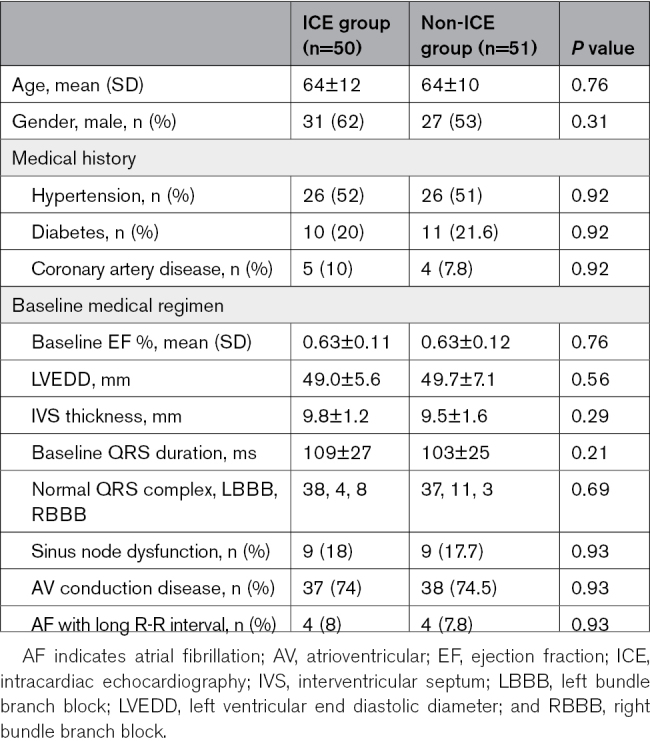
One hundred and one patients (50 patients in the ICE group and 51 patients in the non-ICE group) underwent LBBP implantation. The mean age of patients was 63.8±11.3 years, and men constituted 57.4% of the study population. The LV ejection fraction at baseline was 63±11.5% without LV dysfunction. Indications for pacing were atrioventricular block in 74.3%, sinus node dysfunction in 17.8%, and atrial fibrillation with long R-R interval in 7.9% of the patients. The baseline QRS duration was 106±28 ms, with left bundle branch block in 14.9% and right bundle branch block in 10.9% of the patients. The mean follow-up duration was 6.2±3.5 months (range, 3–12 months). Table 2 shows the baseline characteristics of the patients; no significant differences were observed between the 2 groups.
Table 2.
Baseline Clinical and Demographic Characteristics of Patients Who Underwent Pacemaker Implantation
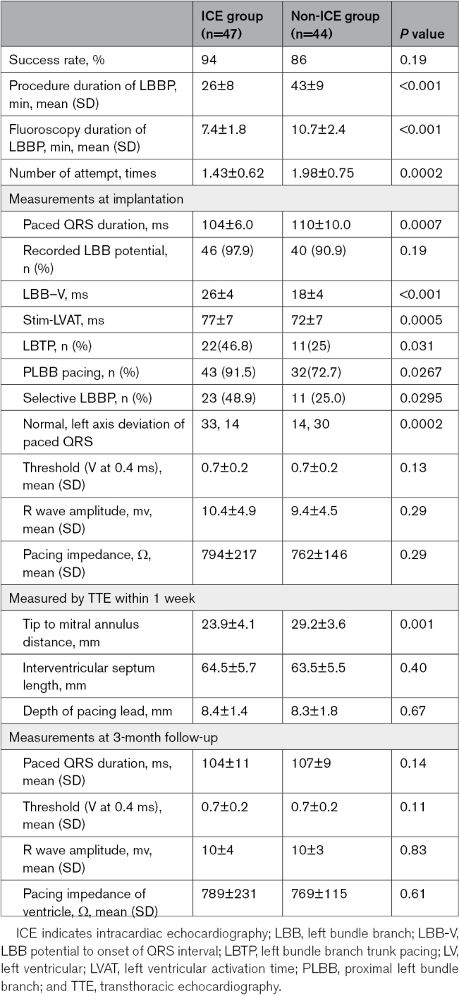
No significant difference was observed in the success rate between the ICE and non-ICE groups (94% versus 86%, P=0.19). In patients with failed LBBP implantation, the pacing lead could not be screwed deep into the LV endocardium, and the paced ECG did not meet the criteria for LBBP. The number of LBBP lead placement attempts in the ICE group was significantly fewer than that in the non-ICE group (1.43±0.62 versus 1.98±0.75, P=0.0002). The procedure interval for LBBP implantation (26±8 versus 43±9 minutes, P<0.001) and duration of fluoroscopy for LBBP implantation (7.4±1.8 versus 10.7±2.4 minutes, P<0.001) in the ICE group were significantly shorter than those in the non-ICE group.
One patient in the ICE group who underwent anticoagulation therapy developed a pocket hematoma, which was resolved without intervention. In the ICE group, there were no vascular complications, such as pseudoaneurysm, arteriovenous fistula, hematoma, and infection, were found after the procedure, and no serious complications such as pulmonary embolism occurred. Lead helix slight break through the LV endocardium (≈1.0 mm) observed by TTE in 3 patients in the non-ICE group, no lead dislodgement or thrombotic events was observed and the pacing parameters were stable in these 3 patients during the 3-month follow-up. No other implantation-related complications were observed during follow-up.
Electrical Characteristics of LBBP
The paced QRS duration in the ICE group was significantly shorter than that in the non-ICE group (104±6.0 versus 110±10.0 ms, P=0.0007). Among the patients with successful LBBP, LBB potentials were recorded in 46 (97.9%) patients from the ICE group and 40 (90.9%) patients from the non-ICE group. The LB-V interval in the ICE group was significantly longer than that in the non-ICE group (26.0±4.0 versus 18.0±4.0ms, P<0.001). The left ventricle activation time in the ICE group was significantly longer than that in the non-ICE group (77.0±7.0 versus 72.0±7.0 ms, P=0.0005). The proportion of selective LBBP in the ICE group was greater than that in the non-ICE group (48.9% versus 25.0%, P=0.0295). More patients in the ICE group achieved PLBB pacing (91.5% versus 72.7%, P=0.0267).
Echocardiography-Based Pacing Lead Tip Location
All patients were assessed using TTE within 1 week of the procedure. The septal length was 64.5±5.7 mm in the ICE group and 63.5±5.5 mm in the non-ICE group (P=0.40). The lead tip location from the MA was 23.9±4.1 mm in the ICE group and 29.2±3.6 mm in the non-ICE group (P=0.001). The lead location from the TA was 16.7±3.1 mm in the ICE group and 22.7±3.4 mm in the non-ICE group (P<0.0001). The distance from the lead tip to the RV subendocardial region was 8.4±1.4 mm in the ICE group and 8.3±1.8 mm in the non-ICE group (P=0.67). The distance from the lead tip to the LV subendocardial region was 1.0±1.4 mm in the ICE group and 1.1±1.1 mm in the non-ICE group (P=0.73; Table 3).
Table 3.
Procedural and Pacing Characteristics of Patients With Successful LBB Pacing
Pacing Parameters
The pacing capture threshold between the ICE and non-ICE groups did not differ significantly at implantation (0.7±0.2 versus 0.7±0.2 V; P=0.13). The sensing amplitude and pacing impedance between the ICE and non-ICE groups did not differ significantly at implantation (Table 3). The pacing parameters (threshold, sensing amplitude, and impedance) remained stable at 3 months (Table 3).
Discussion
The main findings of the present study are as follows:
With ICE guidance and LV septal mapping of the His bundle and LBB potentials, the distribution of the PLBB can be determined approximately in an area of 4.5±1.1 cm2 in the subendocardium of the LV septum.
ICE-guided LBBP lead placement requires a significantly shorter procedure interval and fluoroscopic exposure time than the non-ICE method, and ICE facilitates the successful implantation of the pacing tip near the PLBB.
LBBP at PLBB is characterized by a longer LB-V interval and generates a normal ECG electrical axis in a large number of patients, representing a more effective physiological pacing modality.
LBBP lead implantation guided by fluoroscopy often uses the His bundle signal as an anatomical marker.2,12,13 The entry site of the lead tip under fluoroscopy imaging is affected by variations in the anatomical structure of the heart. Fluoroscopic imaging cannot be used to accurately determine the position of the LBB and the intracardiac structures, which may cause multiple lead screw-in attempts for determining the position of LBB. The LBB has a diffuse fan-like structure that broadly distributes over the left septal surface. Long et al7 showed that after a continuation of the common trunk for 13.8 mm (average), the LBB bifurcated into 2 or 3 divisions, after which the left septal surface is relatively diffusely covered by Purkinje fibers. The distribution of the PLBB can be roughly determined according to the tissue structures, such as aortic sinus, MA, TA, anterior wall, posterior wall, and apex of the LV around the IVS. By analyzing the relationship between the PLBB and the anatomical markers using ICE and 3D electrical mapping, we determined the distribution of the PLBB. Using electrophysiological mapping, we determined that the distribution of PLBB ranged from 20 to 35 mm (29.6±8.3) from the junction between the noncoronary aortic cusp and right coronary aortic cusp and 10 to 20 mm from the TA towards the apex. The pacing lead implanted in this region could successfully achieve PLBB pacing.
LBBP is achieved using the trans ventricular septal method. The depth of the pacing lead helix into the IVS is difficult to confirm using fluoroscopy imaging, and this frequently results in suboptimal lead tip positioning and occasional lead LV perforation. The tip position with a frequent recording of the LBB potential under ICE during the procedure is helpful to confirm whether the helix is adequately deep or breaks through the LV endocardium. In the present study, no lead tip breakthrough into the LV cavity was observed in the ICE group. Conversely, in the non-ICE group, the slight breakage of the pacing lead tip helix through the LV endocardium was more frequent, although the pacing capture threshold and sensing amplitude remained stable during follow-up.
Through TTE, a difference was observed between the 2 groups with respect to the distance of the electrode tip from the MA in patients who underwent successful LBBP. In the ICE group, the electrode tip was closer to the MA; hence, in patients from the ICE group, PLBB capture could be achieved relatively easily. In most patients with LBBP, the pacing site was located at the basal middle LV septum based on ICE or TTE based assessment. The pacing lead tips were positioned at ≈20 to 30 (23.9±4.1 mm) from the MA and 1.0 mm from the left ventricular endocardial surface based on TTE measurement. The lead tip locations in the non-ICE group were distributed at greater distances from the MA.
With the assistance of ICE, the location for PLBB pacing can be determined easily and with greater accuracy, leading to fewer attempts of lead repositioning and a shorter duration of the procedure and x-ray use. On the contrary, multiple lead screwing in attempts are quite common in the search for an appropriate location for LBBP. Multiple screwing in attempts can not only prolong the procedure but also increase the risk of local tissue injury/damage and lead perforation into the LV.
In this study, compared with that in the non-ICE group, a higher proportion of patients in the ICE group received LBBP at the PLBB and showed a normal ECG electrical axis. This finding may suggest that pacing at the PLBB generates a physiological pattern of activation propagation, and thus, a physiological pacing modality. Lin et al10 showed that the pacing of the main LBB truck was performed in ≈25% of patients, whereas the remaining patients received distal LBB or fascicular pacing that led to a shift in the ECG electrical axis in routine LBBP implantation. Whether a shift in the ECG electrical axis represents a change in the LV activation propagation (eg, partial left bundle fascicular block) and a suboptimal LBBP with potential suboptimal clinical outcome is yet to be confirmed. We found a slightly longer left ventricle activation time when PLBB pacing in this study, according to the anatomical and electrophysiological characteristics of the LBB, we have learned that there is no electrical conduction between the PLBB and the surrounding myocardium. When PLBB was pacing, the myocardium must be reactivated through the distal LBB. Therefore, the left ventricle activation time of the PLBB pacing is longer than that of the distal LBBP.
The present study also showed that the ECG QRS duration in the ICE group was significantly shorter than that in the non-ICE group. We hypothesize that PLBB pacing can generate retrograded activation that consequently activates the right bundle branch, leading to a shorter QRS duration compared with that in distal LBBP or left bundle fascicles. A shorter QRS duration with a normal ECG electrical axis suggests that PLBB pacing is more physiological.
Study Limitations
The present study was a single-center prospective, randomized study, and the sample size was relatively small. Although our findings demonstrated that the novel LBBP implantation method was safe and feasible, ICE can be considered expensive at various clinical centers. Possibly, ICE can be selectively used in challenging LBBP implantation or in patients requiring cardiac resynchronization therapy for whom PLBB pacing may be more beneficial.
Conclusions
The basal left ventricular septum can be better visualized using ICE, the LBBP lead tip can be successfully implanted in PLBB region with a shorter duration required for the procedure and fluoroscopy, and generates greater LBB trunk pacing and PLBB pacing.
Article Information
Sources of Funding
This research was funded by the department of science and Technology of Yunnan Province-Kunming Medical University applied basic research (grant no. 2019FE001[-291],202101AY070001-267) and National Natural Science Foundation of China (grant no. 82060071) and Yunnan Applied Basic Research Projects-Union foundation Management System (2019FE001-292) and reserve talents for Yunnan medical academic, China (grant no. H-2019069).
Disclosures
None.
Nonstandard Abbreviations and Acronyms
- 3D
- 3-dimensional
- HBP
- His bundle pacing
- ICE
- intracardiac echocardiography
- IVS
- interventricular septum
- LBB
- left bundle branch
- LBBP
- left bundle branch pacing
- LV
- left ventricle
- MA
- mitral valve annulus
- PLBB
- proximal left bundle branch
- RV
- right ventricular
- TA
- tricuspid valve annulus
- TTE
- transthoracic echocardiograph
W. Huang and J. Fan contributed equally.
For Sources of Funding and Disclosures, see page 221–222.
Contributor Information
XiaoHui Kuang, Email: kxhynsy@sina.com.
Xi Zhang, Email: doggou008@163.com.
YanJu Cui, Email: 547567612@qq.com.
FeiYu Wei, Email: gywfy1988@163.com.
Peng Wu, Email: 745337491@qq.com.
XiaoLong Gao, Email: 247851954@qq.com.
Hong Xiang, Email: 565392512@qq.com.
HaiYan Wu, Email: 745337491@qq.com.
Li-Lin Wang, Email: kmwanglin@163.com.
Xiaohong Zhou, Email: xiaohong.zhou@medtronic.com.
References
- 1.Weijian Huang LS, Shengjie W, Lei X, Fangyi X. Pacing treatment of atrial fibrillation patients with heart failure his bundle pacing combined with atrioventricular node ablation. Card Electrophysiol Clin. 2018;10:519–535. doi: 10.1016/j.ccep.2018.05.016 [DOI] [PubMed] [Google Scholar]
- 2.Vijayaraman P, Subzposh FA, Naperkowski A, Panikkath R, John K, Mascarenhas V, Bauch TD, Huang W. Prospective evaluation of feasibility and electrophysiologic and echocardiographic characteristics of left bundle branch area pacing. Heart Rhythm. 2019;16:1774–1782. doi: 10.1016/j.hrthm.2019.05.011 [DOI] [PubMed] [Google Scholar]
- 3.Dawkins JF, Hu YF, Valle J, Sanchez L, Zheng Y, Marban E, Cingolani E. Antegrade conduction rescues right ventricular pacing-induced cardiomyopathy in complete heart block. J Am Coll Cardiol. 2019;73:1673–1687. doi: 10.1016/j.jacc.2018.12.086 [DOI] [PMC free article] [PubMed] [Google Scholar]
- 4.George K, Massing TNJ. Anatomical configuration of the his bundle and bundle branches in the human heart. Circulation. 1975;53:609–621. doi: 10.1161/01.cir.53.4.609 [DOI] [PubMed] [Google Scholar]
- 5.Tracy CM, Epstein AE, Darbar D, DiMarco JP, Dunbar SB, Estes NAM, Ferguson TB, Hammill SC, Karasik PE, Link MS, et al. 2012 accf/aha/hrs focused update incorporated into the accf/aha/hrs 2008 guidelines for device-based therapy of cardiac rhythm abnormalities. J Am Coll Cardiol. 2013;61:e6–e75. doi: 10.1016/j.jacc.2012.11.007 [DOI] [PubMed] [Google Scholar]
- 6.Okumura Y, Henz BD, Johnson SB, Bunch TJ, et al. Three-dimensional ultrasound for image-guided mapping and intervention methods. Circ Arrhythmia Electrophysiol. 2008;1:110–119. doi: 10.1161/CIRCEP.108.769935 [DOI] [PubMed] [Google Scholar]
- 7.Long DY, Dong JZ, Sang CH, Jiang CX, Tang RB, Yan Q, Yu RH, Li SN, Yao Y, Ning M, et al. Isolated conduction within the left his-purkenje system during sinus rhythm and idiopathic left ventricle tachycardia: findings from mapping the whole conduction system. Circ Arrhythm Electrophysiol. 2013;6:522–527. doi: 10.1161/CIRCEP.113.000293 [DOI] [PubMed] [Google Scholar]
- 8.Anna Mala PO, Dalibor H. Can QRS morphology be used to differentiate between true septal vs. Apparently septal lead placement? An analysis of ECG of real mid-septal, apparent mid-septal, and apical pacing. Eur Heart J Suppl. 2020;22:F14–F22. doi: 10.1093/eurheartj/suaa094 [DOI] [PMC free article] [PubMed] [Google Scholar]
- 9.Huang W, Chen X, Su L, Wu S, Xia X, Vijayaraman P. A beginner’s guide to permanent left bundle branch pacing. Heart Rhythm. 2019;16:1791–1796. doi: 10.1016/j.hrthm.2019.06.016 [DOI] [PubMed] [Google Scholar]
- 10.Jinxuan Lin QH, Keping C, Yan D, Ruohan C, Qi S, Yu’an Z, Lirong Y, Wenzhao L, Yao L, Yuanhao J, et al. Relationship of paced left bundle branch pacing morphology with anatomic location and physiological outcomes. Heart Rhythm. 2021;18:946–953. doi: 10.1016/j.hrthm.2021.03.034 [DOI] [PubMed] [Google Scholar]
- 11.Weijian Huang LS, Shengjie W, Lei X, Fangyi X, Xiaohong Zhou KAE. A novel pacing strategy with low and stable output, pacing the left bundle branch immediately beyond the conduction block. Can J Cardiol. 2017;33:1–3. doi: 10.1016/j.cjca.2017.09.013 [DOI] [PubMed] [Google Scholar]
- 12.Chen K, Li Y. How to implant left bundle branch pacing lead in routine clinical practice. J Cardiovasc Electrophysiol. 2019;30:2569–2577. doi: 10.1111/jce.14190 [DOI] [PubMed] [Google Scholar]
- 13.Li Y, Chen K, Dai Y, Li C, Sun Q, Chen R, Gold MR, Zhang S. Left bundle branch pacing for symptomatic bradycardia: implant success rate, safety, and pacing characteristics. Heart Rhythm. 2019;16:1758–1765. doi: 10.1016/j.hrthm.2019.05.014 [DOI] [PubMed] [Google Scholar]


