Abstract
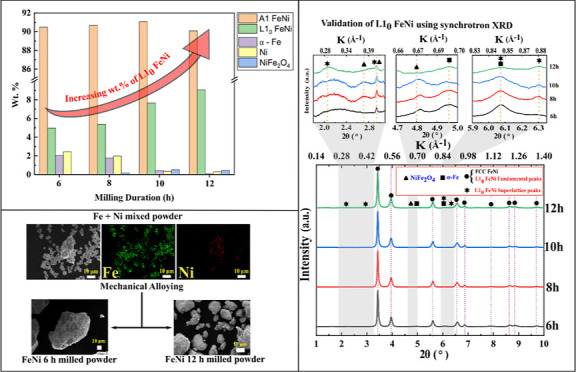
L10-ordered FeNi, tetrataenite, found naturally in meteorites is a predilection for next-generation rare-earth free permanent magnetic materials. However, the synthesis of this phase remains unattainable in an industrially relevant time frame due to the sluggish diffusion of Fe and Ni near the order–disorder temperature (593 K) of L10 FeNi. The present work describes the synthesis of ordered L10 FeNi from elemental Fe and Ni powders by mechanical alloying up to 12 h and subsequent heat treatment at 623 K for 1000 h without a magnetic field and for 4 h in the presence of 1.5 T magnetic field. Also, to address the ambiguity of L10 phase identification caused by the low difference in the X-ray scattering factor of Fe and Ni, synchrotron-based X-ray diffraction is employed, which reveals that 6 h milling is sufficient to induce L10 FeNi formation. Further milling for 12 h is done to achieve a chemically homogeneous powder. The phase fraction of L10-ordered FeNi is quantified to ∼9 wt % for 12 h milled FeNi, which increases to ∼15 wt % after heat treatment. Heat treatment of the milled powder in a magnetic field increases the long-range order parameter (S) from 0.18 to 0.30. Further, the study of magnetic properties reveals a decrease in magnetic saturation and a slight increase in coercivity with the increase in milling duration. At the same time, heat treatment in the magnetic field shows a considerable increase in coercivity.
1. Introduction
Permanent magnetic materials find a wide range of applications in industrial metal separation techniques, energy conversion in motors/generators, medical imaging techniques, data storage, and so forth.1−3 Currently, the majority of the permanent magnet market is dominated by rare earth (RE)-based permanent magnets like Nd-Fe-B and Sm-Co due to their high energy product (BH)max in the order of ∼56 MGOe (445.7 kJ/m3), remanence (Mr) ∼ 14 kG (1.4 T), and coercivity (Hc) ∼ 10 kOe (796 kA/m).4 These magnets have close to ideal permanent magnetic characteristics, that is, high magnetocrystalline anisotropy (Ku) and high saturation magnetization (Ms). High Ku in RE magnets arises from the spin–orbital interaction from the 4f electrons present in the lanthanide series of materials like Nd, Gd, Sm, Tb, Pr, and so forth1,4 and therefore is primarily used in permanent magnets. The dependency on RE elements for high-performance permanent magnets has recently been perceived as a matter of great concern because of the ever-increasing demand for these elements and the corresponding supply constraints.4−6 Hence, sustainable forms of permanent magnets with properties matching those of RE magnets or at least bridging the gap of performance-to-cost ratio between RE magnets and hard ferrites are needed.1,5,7 However, it is difficult to produce high magnetocrystalline anisotropy without the 4f electrons of the RE elements.4,8 Therefore, to develop materials with high magnetocrystalline anisotropy while containing only 3d elements, other possible sources of anisotropy such as domain wall pinning, shape anisotropy, stress anisotropy, and exchange anisotropy were explored.4,9 Apart from intrinsic magnetic properties like Ku and Ms, extrinsic properties like coercivity (Hc) and remanence (Mr) are important to have a large (BH)max.10 Manipulation of Hc and Mr by controlling the microstructure of the material is thus of great interest.2,10
Among all the alternatives to RE-based permanent magnets, L10-ordered materials like FePt, FePd, CoPt, FeNi, and so forth11 have shown great potential due to their high Ku arising from the tetragonal lattice and monoatomic ordering of unlike atomic pairs along the easy magnetization axis. Magnetic compounds crystallizing in the tetragonal L10-ordered structure have received much attention for years considering both the fundamental and technological aspects.12 L10 FeNi2,5−7,13 is of great interest because of its exceptional permanent magnetic properties like high Ku (1.1–1.3 MJ/m3)5 and Ms (14.7 kG),14 abundant constituent elements, and the fact that this ordered phase naturally occurs in meteorites.6,15 The present authors have reported the underlying challenges of L10 FeNi development and current trends to mitigate those issues.13Figure 1a shows the schematic representation of FCC FeNi, and Figure 1b represents different possible orientations of L10 FeNi. It is noteworthy that the presence of L10 phase in equiatomic FeNi was discovered in meteorites in the 1970s. However, the thermodynamic stability of the L10 FeNi phase remained a debated issue for a long time. It was incorporated into the FeNi phase diagram16 after understanding its formation in slowly cooled meteorites. Naturally, L10 FeNi forms in meteorites because of prolonged cooling over millions of years (1–5 K/million years15,17,18). Therefore, commercial production of this phase in bulk is not yet achieved. The formation of L10 FeNi necessitates a very high rate of interdiffusion of Fe and Ni in the FeNi lattice below 593 K (temperature for the order to disorder transformation). In order to induce high rate of diffusion at low temperatures and to achieve the formation of L10 FeNi, several processing techniques such as high energy neutron19,20 or electron21 or ion22 beam irradiation, severe plastic deformation,23−26 mechanical alloying,27,28 and approaches such as crystallization from amorphous FeNiSiPBCu,29,30 field-assisted heat treatment of FeNi31,32 and chemically induced ordering such as nitrogen insertion and topotactic extraction,33 pre-ordered precursor reduction,34 and so forth are studied.
Figure 1.
(a) Disordered FCC FeNi and (b) L10-ordered FeNi structure with alternate stacking of different atoms. Reproduced with permission from ref (13). Copyright 2022 Taylor & Francis.
Mechanical alloying is known to induce ordering in FeAl35 and FeNi28 systems. During mechanical alloying, the formation of ordered versus disordered phases depends on the balance between atomic disordering and thermally activated ordering. Also, the presence of ordered or disordered phases depends on the difference in enthalpies of formation (ΔHf) between those phases.36−38 Thus, the alloy will stay disordered if the enthalpy difference is small; on the other hand, it will become ordered in the case of a large enthalpy difference.36,39 For example, NiAl produced by mechanical alloying of blended elemental powders remains ordered even after milling for long durations,36 whereas ordered FeAl gets disordered under similar conditions. The ΔHf values for NiAl and FeAl are 72 and 25 kJ/mol, respectively, confirming the above argument.36 Similarly, it can be assumed that disordered FeNi forms with ease by mechanical milling as the enthalpy of formation (ΔHf) of L10-ordered FeNi is very small (4.4 kJ/mol).18 Thus, there is a possibility that the ordered FeNi formed during the initial mechanical alloying period gets disordered with increasing milling duration. Rodríguez et al.28 mentioned the formation of L10 FeNi by mechanical alloying for 30 h indicated by the (100) superlattice reflection using conventional X-ray diffraction (XRD). However, it may be noted that the (100) superlattice reflection strongly overlaps with the NiFe2O4 phase, which forms spontaneously and biases the calculation long-range order parameter.
It is established that heat treatment after mechanical alloying could be extremely useful in the formation of ordered structure by altering the thermodynamics and kinetics of phase formation.36,39 However, the sluggish diffusion rate of Fe and Ni atoms near the order–disorder temperature of L10 FeNi (Tod = 593 K) seems to be a serious bottleneck in the synthesis of L10 FeNi in a reasonable time frame.13 Lee et al.23 and Ohtsuki et al.24 studied the effect of heat treatment near 593 K for long durations (1000 h) in FeNi alloy synthesized by high-pressure torsion. Although they carried out heat treatment for 1000 h, the formation of L10-ordered FeNi was extremely low.23,24 Makino et al.29,30,40 studied the crystallization of an amorphous FeNiSiPBCu alloy by heat treatment at 673 K for 288 h. They found that crystallization accelerates diffusion and helps form L10 FeNi (8 wt % and S = 0.8).40 Also, it was highlighted that the order–disorder transformation of L10 FeNi is a kinetically limited process at 593 K, and heat treatment at a slightly higher temperature is beneficial for the formation of L10 FeNi.30 Recent studies have attracted attention toward the application of field-assisted heat treatment for the formation of L10 FeNi in bulk.32 Also, earlier researchers have found that application of magnetic and electric fields during heat treatment can accelerate the thermodynamics and kinetics of phase transformation.41,42 In the present work, dual drive planetary ball mill (DDPBM) is used for mechanical alloying of Fe and Ni powders for different durations (6–12 h). Eventually, the effect of heat treatment in magnetic field was studied for the formation of L10 ordering in milled FeNi powder. The present work also highlights the use of synchrotron-based high-energy XRD (SXRD) to detect the superlattice reflections. The long-range ordering parameter (S) is computed using (001) and (210) superlattice reflections. Rietveld refinement is performed to quantify the phases. This work demonstrates that a shorter milling duration of 6 h in DDPBM is sufficient to induce the formation of L10 FeNi, and subsequent heat treatment with 1.5 T field applied is effective in increasing the ordering parameter and phase content of L10-ordered FeNi. The magnetic properties of the mechanically alloyed FeNi before and after heat treatment are also highlighted.
2. Materials and Methods
2.1. Mechanical Alloying of Fe and Ni Micropowder
The FeNi alloy powder was prepared by mechanical alloying using elemental powders of Fe (99.95% purity, 5–10 μm, Alfa Aesar Inc.) and Ni (99.97% purity, 5–10 μm, Alfa Aesar Inc.). Initially, Fe and Ni powders were mixed in 50:50 at. % using a turbo mixer (Alphie, India) for 3 h to get a uniform blending. The blended elemental powders were dry-milled using a high-energy dual-drive planetary ball mill (Egoma, India) for 6, 8, 10, and 12 h. Milling was performed using a hardened steel vial and balls (10 mm diameter). The elemental powder mix was sealed in the vial with pressurized argon to prevent the powder’s oxidation during high-energy ball milling. The ball-to-powder ratio was 8:1. To avoid overheating of the vials, mechanical alloying was conducted intermittently in 1 h steps. The speed of the vial around its own axis was 300 and 150 rpm around the mill’s main axis. Milling was carried out at ∼73% of the critical speed. Detailed calculations of the critical speed for dual-drive ball milling can be found in ref (43).
2.2. Heat Treatment of Mechanically Alloyed FeNi Powder
Owing to the chemical homogeneity and presence of L10 FeNi, the 12 h milled FeNi powder was used for further heat treatment experiments. The 12 h milled powder was sealed inside a quartz tube under a vacuum of 10–3 mbar to prevent oxidation during heat treatment. The temperature for heat treatment is selected to be 623 K pertaining to the findings that the order–disorder transformation of L10 FeNi is a thermally activated and kinetically limited process, and higher rate of disordering is prominent after 678 K.18 The as-milled powder was heat-treated in a quartz tubular furnace (Nano Tech., India) for 1000 h in a vacuum atmosphere. After 1000 h of heat treatment, the sample was taken out and placed inside a magnetic field-assisted furnace (Marine India, India) for 4 h under an applied magnetic field of 1.5 T, argon atmosphere. After 4 h, the powder was quenched with argon at ∼ 40 K/min to room temperature in the presence of magnetic field. Figure 2a shows the magnetic field-assisted heat treatment setup, and Figure 2b shows the schematic diagram for the furnace.
Figure 2.
(a) Image of magnetic field-assisted heat treatment setup and (b) schematic diagram of the furnace.
2.3. Characterization Techniques
The structural properties of milled samples were determined using XRD utilizing a Rigaku 88 Ultima IV diffractometer with Cu-Kα (λ = 1.5418 Å) operating at 30 kV and 40 mA. Synchrotron high-energy X-ray diffraction (SXRD) was carried out at beamline P07 of PETRA-III, DESY, Hamburg, Germany. The powder samples were mounted along the X-ray beam in low-absorption glass cuvettes (1.5 mm deep on the inside). A high-energy X-ray beam with energy E = 100 keV (λ = 0.12415 Å, spot size 800 × 800 μm2) was directed on the FeNi-alloyed powders. Transmission diffraction patterns were collected using a PerkinElmer detector, featuring a 2048 × 2048-pixel array and a pixel size of 200 × 200 μm2. The 2θ range and the sample to detector distance were calibrated using the LaB6 standard powder. The samples were positioned at 1437.5 mm away from the detector, and the detector exposure time was 1s. The recorded two-dimensional transmission diffraction rings were azimuthally integrated using Fit2D44 to obtain one-dimensional diffraction patterns in the 2θ range of 1–10°. Finally, the diffraction patterns were analyzed by the Rietveld method using the FullProf program suite.45−47 SXRD measurements after heat treatment of the milled FeNi powder have been performed using the ADXRD beamline (BL-12) at Indus-2, the Indian synchrotron radiation source. Measurements were performed on a six-circle diffractometer (Huber 5020) using a one-dimensional position-sensitive detector (Mythen). The X-ray wavelength used in the present study is 0.7559 Å and was accurately calibrated by measuring the XRD pattern of the NIST LaB6 standard. Powder morphology was studied using a SEM JSM-6510 (JEOL, Japan) at an accelerating voltage of 20 kV. The 12 h milled FeNi powder was dispersed in isopropanol and transferred to the carbon-coated Cu-TEM grid. High-resolution transmission electron microscopy (TEM) analysis was carried out in a JEM-F200 (JEOL, Japan) and operated at 200 kV. The variation of magnetization of FeNi powders ball-milled for different durations was investigated using a vibrating sample magnetometer attached to a physical property measurement system (Quantum Design, USA).
3. Results and Discussion
3.1. Morphology of Mechanically Milled Powders
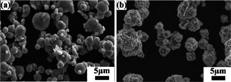
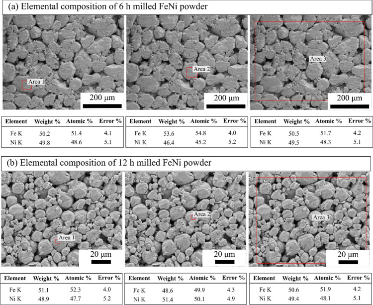
Figure 3 shows the morphology of the as-received Fe and Ni powders. As revealed from Figure 3a, Fe particles are spherical in shape with particle size between 5 and 10 μm, while the Ni powder is spiky in shape with particle size between 5 and 10 μm (Figure 3b). The as-received Fe and Ni powders were mixed (50–50 at. %) for 3 h in a turbo mixer. Figure 4 shows the elemental maps of the mixed powder, which indicate that upon 3 h of mixing, the Fe particles are mechanically interlocked with the Ni particles. The 3 h mixed Fe–Ni powders were further subjected to high-energy ball milling up to 12 h in DDPBM. In a DDPBM, four different forces act on the particles, that is, centrifugal force about gyrating axis, centrifugal force about milling axis, Coriolis force, and gravitational force on grinding media. Simultaneous action of these forces creates a strong acceleration field, which causes the Fe and Ni particles to flatten and stack on top of each other, forming a laminar composite. Due to subsequently repeated cold-welding, fracturing, and rewelding, the FeNi alloy is formed. These alloyed FeNi particles are further flattened to a flake-like structure, which gets agglomerated due to an increase in the specific surface area. Figure 5a shows the morphology of 6 h milled powder displaying an irregular, convoluted particle shape. Further milling up to 12 h resulted in the formation of much finer particles with greater convolutions, as shown in Figure 5b. Figure 6a,b shows the elemental composition of the marked areas of 6 and 12 h milled powder. In the 6 h milled FeNi powder, the Fe and Ni content was found to be 51.8 ± 3.2 and 48.2 ± 2.1 at. %, respectively. On the other hand, the composition of the 12 h milled FeNi powder was found to be 50.5 ± 3.0 at. % Fe and 49.5 ± 4.2 at. % Ni. It is also to be noted that the average composition of L10 FeNi containing meteorite is Fe: 50.47 ± 1.98 at. % and Ni: 49.60 ± 1.49 at. %,48 which is close to the composition of the milled powder.
Figure 3.
Scanning electron microscopy (SEM) images showing the morphology of the as-received (a) Fe powder and (b) Ni powder.
Figure 4.
(a) SEM image of 3 h of mixed Fe and Ni powder. (b,c) Elemental mapping of Fe and Ni, respectively.
Figure 5.
SEM images of mechanically alloyed FeNi after (a) 6 and (b) 12 h of milling.
Figure 6.
EDS elemental analysis of mechanically alloyed FeNi after (a) 6 and (b) 12 h of milling.
3.2. Structural Determination and Phase Quantification of Mechanically Milled FeNi
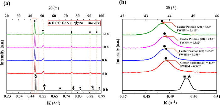
Figure 7a illustrates the XRD patterns of 6, 8, 10, and 12 h milled FeNi powders. After 6 h of milling, pure Fe and Ni peaks are not visible. Also, with increased milling duration, the FeNi peaks shift toward smaller diffraction angles and get slightly broader (Figure 7b). These peaks can be indexed as disordered FeNi and/or fundamental reflections of the L10 FeNi phase. No superlattice reflections are observed or could not be resolved from the background of the XRD pattern as the intensity ratios of the strongest superlattice peaks and fundamental peaks are as small as 0.3%.40 In order to observe possible superlattice reflections and to unravel the phase evolution with milling time, SXRD was carried out, where the background noise is considerably lower compared to conventional laboratory XRD. To analyze the constituent phases in the milled powder, standard patterns of probable phases are calculated based on their crystal lattice structures, space groups, atomic positions, and lattice parameters. Figure 7 shows the calculated patterns of L10 FeNi, A1 FeNi, NiFe2O4, α-Fe, and Ni.
Figure 7.
(a) XRD patterns of pristine Fe and Ni powder mixture under different milling durations and (b) magnified view of XRD patterns in the K range of 0.47–0.51 Å–1.
The standard pattern (Figure 8) of L10 FeNi contains superlattice reflections with h + k + l = 2n + 1, that is, (001), (100), (201), and (210) along with fundamental reflections with h + k + l = 2n, that is, (101), (110), (200), (211), and so forth. The fundamental reflections of L10 FeNi strongly overlap with the reflections of A1 FeNi and Ni. Comparison of the standard patterns of L10 FeNi and NiFe2O4 shows that the (100) superlattice reflection and the (101), (200), and (202) fundamental reflections of L10 FeNi coincide with the (311), (400), (533), and (731) reflections of NiFe2O4. The (201) superlattice reflection of L10 FeNi is close to the (211) fundamental reflection of α-Fe.
Figure 8.
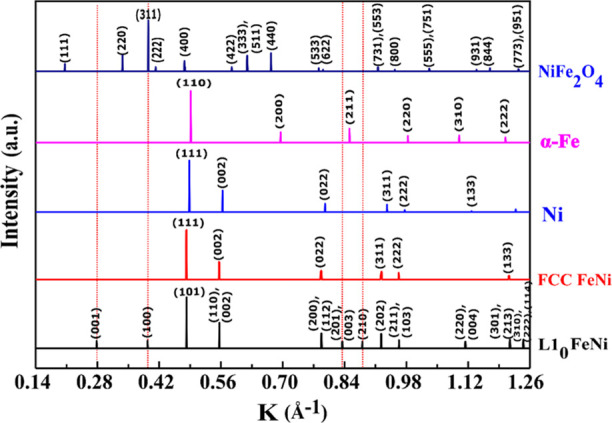
Standard patterns of various constituent phases along with the miller indices of respective peaks, represented in K-space.
The SXRD patterns of milled FeNi powders are presented in Figure 9, which reveals the formation of L10 FeNi during milling as indicated by the presence of (001), (100), (201), and (210) superlattice reflections. Distinct peaks at K = 0.38 Å–1 (2θ = 2.70°) and K = 0.67 Å–1 (2θ = 4.80°) are observed, corresponding to the (220) and (440) peaks of NiFe2O4, respectively. This indicates the presence of small traces of oxides that may have formed during material handling. A similar observation was also reported by Goto et al.33 Furthermore, a distinct peak is observed at K = 0.70 Å–1 (2θ = 4.96°), corresponding to the (200) peak of α-Fe (see Figure 9).
Figure 9.
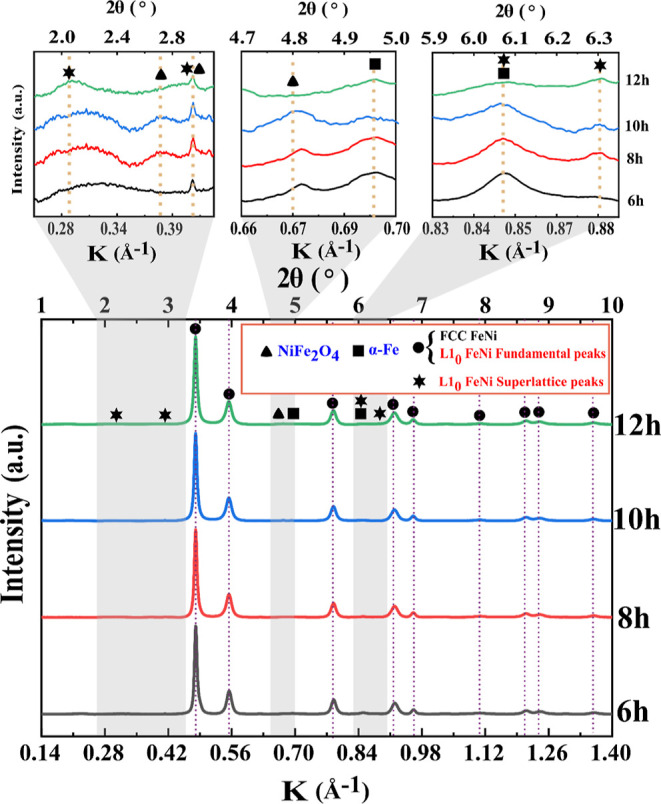
Synchrotron high-energy XRD patterns of mechanically alloy FeNi powders.
The SXRD patterns of 6, 8, 10,
and 12 h milled
powders were subjected
to the Rietveld refinement procedure for quantification of phases.
The crystal structures of L10 FeNi, A1 FeNi, NiFe2O4, α-Fe, and Ni were defined according to Table 1 and were considered
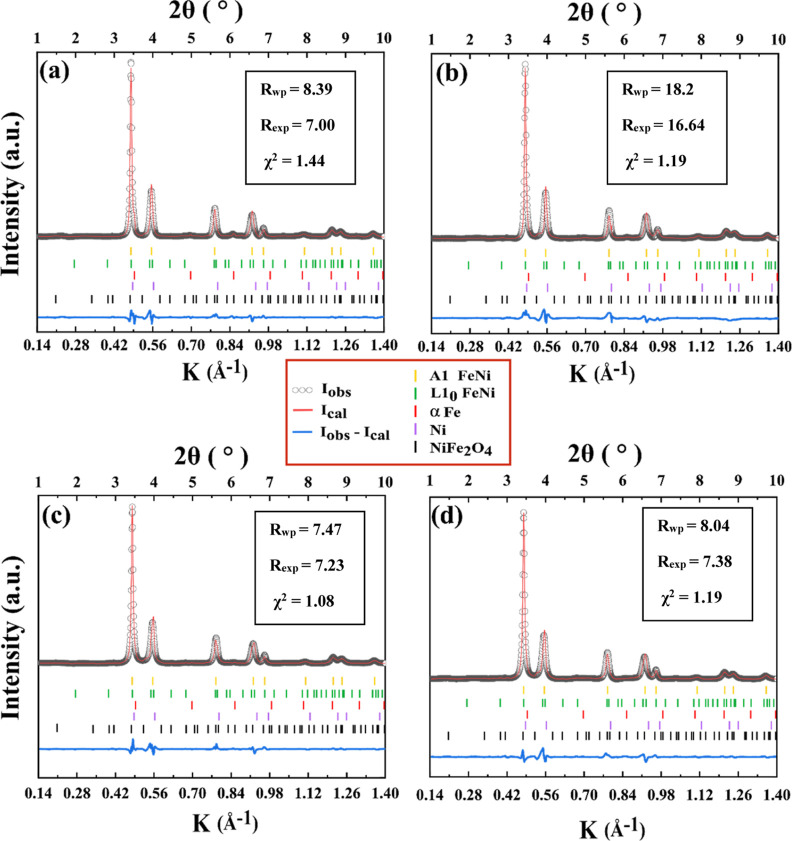
for evaluation. Figure 10 shows the fitted patterns of 6, 8, 10, and 12 h milled FeNi
powders. The quality of Rietveld refinements is quantified by the
chi-squared values [ ], where Rwp and Rexp are
the weighted profile R-factor
and expected R-factor, respectively. The values of χ2, Rwp, and Rexp are also shown in Figure 10. The difference between experimental and calculated intensities
is presented below each pattern fit. Table 1 summarizes refined lattice parameters of
constituting phases. The weight fractions of contributing phases for
6, 8, 10, and 12 h milled FeNi powder are shown in Figure 11. It shows that disordered
A1 FeNi is the major phase, which amounts to about 90 wt %. Only minor
amounts of α-Fe and Ni (<2 wt %) are present in the milled
FeNi samples. This indicates that the starting elemental powders (Fe
and Ni) have completely reacted to form FeNi alloy. It is worth noting
that the amount of unreacted α-Fe and Ni decrease with the increase
in the milling duration from 6 to 12 h.
Table 1. Crystallographic Characteristics of Phases in Milled FeNi Powders.
| refined
cell parameters |
|||||
|---|---|---|---|---|---|
| phase (space group) | atom | Wyckoff site | occupancy | a (Å) | c (Å) |
| A1 FeNi (Fm3̅m) | Fe | 4a | 0.5 | 3.59 ± 0.02 | |
| Ni | 4a | 0.55 | |||
| L10 FeNi (P4/mmm) | Fe | 4a | 1 | 2.53 ± 0.01 | 3.64 ± 0.01 |
| Ni | 4d | 1 | |||
| α-Fe (Im3̅m) | Fe | 2a | 1 | 2.86 ± 0.00 | |
| Ni (Fm3̅m) | Ni | 4a | 1 | 3.55 ± 0.02 | |
| NiFe2O4 (Fd3̅m) | Fe | 8b | 1 | 8.35 ± 0.00 | |
| Fe + Ni | 16c | 0.5 + 0.5 | |||
| 4 O | 32e | 1 | |||
Figure 10.
Rietveld whole profile analysis of the SXRDs of (a) 6, (b) 8, (c) 10, and (d) 12 h mechanically milled FeNi powders.
Figure 11.
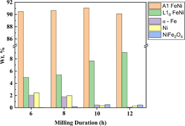
Phase fraction (wt %) of constituting phases in mechanically milled FeNi powders obtained using the Rietveld method.
The NiFe2O4 oxide phase content increases with an increase in milling duration. For the 6 h milled powder, the oxide phase amounts to 0.04 wt %, while it amounts to 0.46 wt % in the case of 12 h milled powder. It is important to note that milling was carried out in a high-purity argon atmosphere, and a pressure of 3 MPa was maintained during the milling. Therefore, oxidation during milling is unlikely to occur. However, the formation of NiFe2O4 as an oxidation product is possible by oxygen pickup during material handling and characterization. The increase in the content of NiFe2O4 from 6 to 12 h milled FeNi powder can be rationalized by a decrease in particle size with milling duration. The reduced particle size, in turn, increases the surface area-to-volume ratio and aggravates spontaneous oxidation. From Figure 11, it can be seen that the 6 h milling time induces the formation of 5.0 wt % L10 FeNi. With the increase in milling time to 12 h, L10 FeNi amounts to 9.0 wt %. The results suggest that milling promotes the mechanochemical reaction of the starting powders to form A1 FeNi and L10 FeNi. Similar to our finding, Rodríguez et al.28 reported ∼9 wt % of L10 FeNi after 30 h of milling in a shaker-type ball. However, the presence of oxides and unreacted Fe and Ni was not considered during the Rietveld refinement. It is important to note that, in the present work, ordered L10 FeNi is formed after 6 h milling using a DDPBM in place of a shaker-type mill. This suggests that DDPBM is more effective in alloying FeNi than shaker-type ball milling.
The crystallite size and microstrain induced by mechanical milling were obtained from the Rietveld refinement. For the estimation, the fundamental peaks of L10 FeNi, which also coincide with those of the A1 FeNi phase, were considered. The peak broadening of X-ray Bragg reflections can result from two major factors: reduction in crystallite size and increase of microstrain. It is observed that the crystallite size decreases with an increase in milling duration, whereas the microstrain increases slightly from 6 to 8 h of milling and then decreases with further milling (see Figure 12). This result suggests that the lattice distortion and generation of defect density are minimal with respect to milling carried out in the present investigation.
Figure 12.
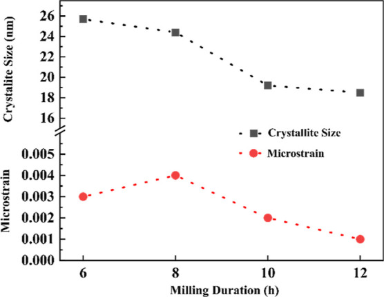
Variation of crystallite size and microstrain with respect to milling durations.
From the SXRD patterns, the long-range-order parameter (S) is calculated by the following equation
 |
1 |
where Isup and Ifund are integrated intensities of the superlattice and fundamental peaks, respectively. The superscripts “obs” and “cal” stand for observed and calculated intensities of the peaks. The (100) superlattice reflection of L10 FeNi coincides with the (311) peak of NiFe2O4. Also, the (211) peak of α-Fe and the (201) peak of L10 FeNi are visibly overlapped at 2θ = 6.07° (K = 0.85 Å–1) (see Figures 7 and 9). Rietveld refinements of the SXRD patterns of the milled samples indicate the presence of <0.6 wt % of NiFe2O4 and <2 wt % of α-Fe. Therefore, (100) and (201) reflections are not considered for the calculation of S. On the other hand, the (001) and (210) superlattice reflections are of the same intensity as the (100) superlattice reflection, and they do not overlap with the other phases. Thus, the (001) and (210) superlattice reflections are considered in order to calculate S. The S values are estimated as 0.17, 0.18, 0.18, and 0.17 for milling duration of 6, 8, 10, and 12 h, respectively. It is observed that the value of S is almost constant irrespective of milling duration. In this context, it is to be noted that the S parameter for meteoritic samples is calculated as 0.6.48 Takanashi et al.49 synthesized L10 FeNi thin films by alternate layer deposition using molecular beam epitaxy and reported S values in the range of 0.2–0.4 depending on the type of substrates and film thickness. Recently, Goto et al. showed a higher value of S = 0.71 during bulk formation L10 FeNi by nitrogen insertion and topotactic extraction method.33 Crystallization of amorphous (Fe, Ni)SiBPCu alloy showed S = 0.8.40Table 2 shows the comparison of ordering parameter (S) obtained from different natural and artificial sources; compared to the above-mentioned methods, the S parameter obtained by mechanical alloying is low. To the best of the knowledge of the authors, this is the first report on the ordering parameter of milled Fe–Ni powders. In the literature, the ordering parameter of the milled FeNi was not registered, probably due to the very low intensity ratio of the superlattice to fundamental reflections in a conventional XRD setup. In this work, high-energy Synchrotron XRD was utilized to quantify the ordering parameter of the milled FeNi powder.
Table 2. Comparison of Long-Range Ordering Parameter (S) Available in the Literature.
| sl. no. | processing technique | vol % of L10 FeNi | long-range ordering parameter (s) | FeNi particles shape and size | refs |
|---|---|---|---|---|---|
| 1 | natural meteorite (NWA 6259) | 95 | 1 μm thick ring along grain boundary of FCC FeNi | (14) | |
| 2 | neutron irradiation of FeNi single crystal | 0.41–0.45 | (19, 20) | ||
| 3 | cyclic oxidation and reduction of Ni-coated Fe | 19 | (51) | ||
| 4 | deposition of monoatomic layer of Fe and Ni using molecular beam epitaxy | 0.2–0.6 | (49) | ||
| 5 | nitrogen insertion and topotactic extraction | 0.71 | <40 nm single phase particles | (33) | |
| 6 | mechanical alloying of Fe and Ni powder for 90 h in a shaker-type mill | absent | 12–17 nm particles | (27) | |
| 7 | mechanical alloying of Fe and Ni powder for 90 h in a shaker-type mill | 9 | (28) | ||
| 8 | crystallization from amorphous FeNiSiBPCu bulk metallic glass | 8 | 0.8 | 30–50 nm sized polycrystalline grains | (29, 30, 40) |
| 9 | crystallization from amorphous FeNiPC bulk metallic glass | <100 nm dispersed in bulk | (52) | ||
| 10 | high-pressure torsion of FeNi and heat treatment | absent | (25) | ||
| 11 | mechanical alloying of Fe and Ni powders in DDPBM | 9 | 0.18 | this work | |
| magnetic field-assisted heat treatment of 12 h milled FeNi prepared by DDPBM | 15 | 0.3 |
Usually, the value of S in mechanically alloyed powders is not very high since mechanical alloying is an energy-intensive process where repeated fracture, breaking, and welding of powder particles take place.36,39 For example, in the NiAl50 system, the value of S decreases from 0.7 to 0.5 with an increase in milling energy from 200 to 700 kJ/kg. Also, in the FeAl35 system, ordering decreases with the increase in milling time. In general, the S value of mechanically alloyed powder can be improved by annealing or heat treatment due to annihilation of defects and subsequent increase in diffusion.35,36,39 However, the FeNi system is an exception, as the heat treatment of the FeNi powder below order–disorder temperature (593 K) will require astronomical time to induce sufficient diffusion for improving the ordering quantity.27 Therefore, in future, the effect of electric and magnetic fields on the milled FeNi powder during heat treatment below order–disorder transformation temperature toward the formation of L10 FeNi will be studied.
3.3. TEM Study of Mechanically Alloyed FeNi
Figure 13a,b shows the bright-field low-magnification TEM image of the 12 h milled FeNi powder and the corresponding high-resolution TEM image. Figure 12a depicts the flaky (flattened) morphology and the crystalline nature of the ultra-fine particles. It is to be noted that in DDPBM, the initial particles are flattened due to the large impact energy from the grinding media. With further milling, these flattened particles break, generating more surface areas. Due to the increased specific surface area, these flattened particles are aggregated, and a convoluted structure is formed (see Figure 5). Similar results are also reported by Debata et al.53 in the 95W-3.5Ni-1.5Fe system and Pandey et al.54 in oxide dispersion-strengthened ferritic steel. The fast Fourier transform (FFT) pattern corresponding to the red square marked in Figure 13b is shown in Figure 13c. It is to be noted that the FFT pattern is strongly overlapping with both L10 FeNi and A1 FeNi (B.D. L10 [100]||B.D. A1 [110]). The (001) and (100) superlattice reflections of L10 FeNi, which correspond to 0.364 and 0.252 nm, respectively, are not visualized even after several attempts. As the quantity of L10-ordered FeNi in the bulk 12 h milled powder is extremely low (∼9 wt %), the intensity of the superlattice structures is very weak. Thus, it is almost difficult to find a region containing ordered structure and confirm the presence of L10 structure in bulk powder even if it is present in the sample. The red circled spots show d-spacings of 0.143 nm, corresponding to the presence of the (200) plane of unreacted α-Fe.
Figure 13.
(a) Bright-field low-magnification TEM image of the 12 h milled FeNi powder and corresponding (b) high-resolution image and (c) FFT pattern corresponding to the red squared region in (b). (White and yellow colors represent the planes of L10 FeNi and A1 FeNi, respectively. The red circled spots highlight the presence of (200) plane of α-Fe corresponding to d-spacings of 0.143 nm.)
3.4. Effect of Field-Assisted Heat Treatment on L10 FeNi Phase Formation
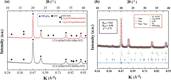
Figure 14a compares the SXRD patterns of the 12 h milled FeNi (black color) and heat-treated (1000 h without field + 4 h in 1.5 T field) (red color). It can be noted that the heat-treated FeNi powder shows sharper and narrower peaks (fundamental and superlattice) compared to the 12 h milled FeNi powder. The value of S was calculated using the intensities of (001); (210) peaks were found to be 0.35 for the heat-treated powder. It was found that the crystallite size for the 12 h milled FeNi powder is ∼45 nm, which increases to 52 nm after heat treatment. Also, the internal strain decreased to 8.2 × 10⁻⁴ after heat treatment, which is 10 times less than the 12 h milled condition (see Figure 14). Figure 14b shows the Rietveld refinement of the SXRD patterns of the heat-treated sample using the same structural parameters as listed in Table 1. The Rietveld refinement reveals that the concentration of L10 FeNi in the as-milled condition is ∼15 wt %. The values of χ2, Rwp, and Rexp are also shown in Figure 14b.
Figure 14.
(a) SXRD pattern of 12 h milled FeNi (black) and heat-treated FeNi (red) powders. (b) After heat treatment, Rietveld whole profile analysis of the SXRDs of 12 h mechanically milled FeNi powders.
3.5. Effect of Milling and Field-Assisted Heat Treatment on FeNi Powder
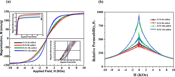
The hysteresis curves of mechanically milled FeNi powders are shown in Figure 15. These curves show a magnetic behavior that is typical of a soft magnetic material (low coercivity (Hc) with relatively high saturation magnetization (Ms)). The Ms value of the milled powders decreases with increasing milling duration. For the 6 h milled sample, the Ms value was found to be 145 emu/g, which decreases to 137.5 emu/g upon 12 h of milling. The decrease in Ms may be caused by the reduction in the elemental Fe and Ni content and the increase in oxide-phase (NiFe2O4) content. The effect of decreasing α-Fe and Ni content on the overall saturation magnetization is dominant due to their high magnetic saturation values of 217.6 and 55.1 emu/g, respectively. The Hc of the milled FeNi powder increases with increasing milling duration. For 6, 8, 10, and 12 h milled powders, the Hc values are 3, 8, 10, and 12 Oe, respectively. Hc is an extrinsic property that depends on the shape, size, and microstructure of powder. With an increase in milling duration, the particle size decreases, and there is an increase in defect concentration. The increase in defects restricts the movement of the domain walls, which subsequently causes the increase in Hc. A similar effect was reported by Geng et al.27 at much higher milling durations where there is no significant phase change, but Hc increases with milling duration. Figure 15b compares relative permeability (μr = B/H) with respect to the applied field of −40 to 40 kOe. It can be observed from Figure 15 that μr initially decreases from 6 to 8 h of milling and increases with further milling up to 12 h. This data verifies the earlier observation by Geng et al.27 that an initial increase in milling duration induces macrostrain and a high volume of defects, which in turn hinders the motion of the magnetic domains and thus requires a higher external magnetic field to reach saturation. In contrast, a further increase in milling time decreases the microstrain, which causes easy movement of the magnetic domains, leading to magnetic saturation at a relatively lower external magnetic field.
Figure 15.
(a) M–H curves and (b) μr vs H for mechanically milled FeNi powders.
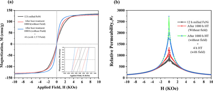
Figure 16 shows the effect of heat treatment (with and without an applied field) on the hysteresis of 12 h milled FeNi. From Figure 16a, it can be seen that there is no change in the magnetic saturation which is excepted as Ms is an intrinsic property and does not depend on the microstructure and shape of the particles. From the magnified M versus H plot (subset Figure 16a), it can be observed that there is a significant increase in Hc after 1000 h heat treatment accompanied by a 4 h heat treatment in the magnetic field (30 Oe). This increase in Hc can be associated with the increase in the L10 FeNi phase and not due to the grain refinement because after heat treatment, it is assumed that the defect concentration decreases and the grain size increases. Further analysis of μr versus H curve in Figure 16b reveals that there is a subtle increase in μr after 1000 h heat treatment without field and again after 4 h heat treatment in the presence of an external magnetic field. This can be due to the increase in grain size and subsequent alignment of magnetic domains along the magnetic easy axis due to the heat treatment procedure.
Figure 16.
(a) M–H curves and (b) μr vs H for 12 mechanically milled FeNi powders before and after heat treatment.
4. Conclusions
The current work demonstrates the formation of L10 FeNi using dual-drive planetary ball milling and subsequent heat treatment at 623 K for 1000 h without a magnetic field and 4 h in the presence of an external magnetic field of 1.5 T. The important findings of this study are as follows:
-
(a)
6 h milling is sufficient to induce the formation of L10 FeNi. The phase fraction of L10 FeNi in the 6 h milled powder is 5 wt %, which increases to ∼9 wt % upon further milling up to 12 h.
-
(b)
The long-range ordering parameter (S) was calculated using the (001) and (210) superlattice reflections of L10 FeNi, and the value of S is found to be constant at 0.18 for all samples collected at different milling durations (6–12 h).
-
(c)
Heat treatment in the presence of external magnetic field enhances the phase fraction of L10 FeNi up to ∼15 wt %. Also, it improves the S to 0.3, which is commendably close to the reported values in some meteorites.
-
(d)
Hc value increases with the increase in milling duration, which is attributed to the increase in L10 phase fraction. In addition to this, heat treatment in the presence of a magnetic field increases Hc owing to the increase in L10 phases fraction.
-
(e)
Microstrain initially increases up to 8 h of milling and decreases with further milling. An increase in microstrain restricts the movement of the domain walls causing increases in magnetocrystalline anisotropy. Therefore, it is found that the relative permeability (μr) initially decreases with milling duration (up to 8 h) and increases with further milling (up to 12 h). Heat treatment of the 12 h milled FeNi powder in the presence of an external magnetic field results in a higher μr value due to the alignment of domains along the easy axis.
In summary, the field-assisted heat treatment proves to be effective in improving the phase fraction and long-range ordering of L10 FeNi produced by mechanical alloying.
Acknowledgments
Shuvam Mandal would like to thank Council of Scientific & Industrial Research (CSIR) for research fellowship (31/GATE/09(14)/2018-EMR-I) and Academy of Scientific and Innovative Research (AcSIR), India, for allowing research activity through a Ph.D. program. We acknowledge Central Characterization Department, CSIR-IMMT Bhubaneswar, India, for XRD and SEM characterization. Dr. K Jayasankar, CSIR-NIIST Thiruvananthapuram, India, is acknowledged for magnetic characterization. We acknowledge DESY (Hamburg, Germany), a member of Helmholtz Association HGF, for provision of experimental facilities. Part of research was carried out at PETRA III, and we would like to thank Dr. Andreas Stark, Dr. EmadMaawad, and Dr. Norbert Schell for assistance in using beamline P07 within the proposal I-20190769. We acknowledge Dr. Archana Sagdao for assisting in using beamline 12 at Indus-2 at RRCAT Indore, India (UGC-DAE-CSR project—CRS/2021-22/01/417).
The authors declare no competing financial interest.
References
- Coey J. M. D. Perspective and Prospects for Rare Earth Permanent Magnets. Engineering 2020, 6, 119–131. 10.1016/j.eng.2018.11.034. [DOI] [Google Scholar]
- Gutfleisch O.; Willard M. A.; Brück E.; Chen C. H.; Sankar S. G.; Liu J. P. Magnetic Materials and Devices for the 21st Century: Stronger, Lighter, and More Energy Efficient. Adv. Mater. 2011, 23, 821–842. 10.1002/adma.201002180. [DOI] [PubMed] [Google Scholar]
- Coey J. M. D. Permanent Magnet Applications. J. Magn. Magn. Mater. 2002, 248, 441–456. 10.1016/s0304-8853(02)00335-9. [DOI] [Google Scholar]
- Lewis L. H.; Jiménez-Villacorta F. Perspectives on Permanent Magnetic Materials for Energy Conversion and Power Generation. Metall. Mater. Trans. A 2013, 44, 2–20. 10.1007/s11661-012-1278-2. [DOI] [Google Scholar]
- Cui J.; Kramer M.; Zhou L.; Liu F.; Gabay A.; Hadjipanayis G.; Balasubramanian B.; Sellmyer D. Current Progress and Future Challenges in Rare-Earth-Free Permanent Magnets. Acta Mater. 2018, 158, 118–137. 10.1016/j.actamat.2018.07.049. [DOI] [Google Scholar]
- Lewis L. H.; Mubarok A.; Poirier E.; Bordeaux N.; Manchanda P.; Kashyap A.; Skomski R.; Goldstein J.; Pinkerton F. E.; Mishra R. K.; Kubic Jr R. C.; Barmak K. Inspired by Nature: Investigating Tetrataenite for Permanent Magnet Applications. J. Phys.: Condens. Matter 2014, 26, 064213. 10.1088/0953-8984/26/6/064213. [DOI] [PubMed] [Google Scholar]
- Li D.; Li Y.; Pan D.; Zhang Z.; Choi C. J. Prospect and Status of Iron-Based Rare-Earth-Free Permanent Magnetic Materials. J. Magn. Magn. Mater. 2019, 469, 535–544. 10.1016/j.jmmm.2018.09.032. [DOI] [Google Scholar]
- Skomski R.; Manchanda P.; Kumar P. K.; Balamurugan B.; Kashyap A.; Sellmyer D. J. Predicting the Future of Permanent-Magnet Materials. IEEE Trans. Magn. 2013, 49, 3215–3220. 10.1109/tmag.2013.2248139. [DOI] [Google Scholar]
- Kuz’Min M. D.; Skokov K. P.; Jian H.; Radulov I.; Gutfleisch O. Towards High-Performance Permanent Magnets without Rare Earths. J. Phys.: Condens. Matter 2014, 26, 064205. 10.1088/0953-8984/26/6/064205. [DOI] [PubMed] [Google Scholar]
- Gutfleisch O. Controlling the Properties of High Energy Density Permanent Magnetic Materials by Different Processing Routes. J. Phys. D: Appl. Phys. 2000, 33, R157–R172. 10.1088/0022-3727/33/17/201. [DOI] [Google Scholar]
- Klemmer T.; Hoydick D.; Okumura H.; Zhang B.; Soffa W. A. Magnetic Hardening and Coercivity Mechanisms in L10 Ordered FePd Ferromagnets. Scr. Metall. Mater. 1995, 33, 1793–1805. 10.1016/0956-716x(95)00413-p. [DOI] [Google Scholar]
- Errandonea D. Tight-Binding Study of the Electronic and Magnetic Properties of an L10 Ordered FeCu Alloy. Phys. Lett. A 1997, 233, 139–142. 10.1016/s0375-9601(97)00419-2. [DOI] [Google Scholar]
- Mandal S.; Debata M.; Sengupta P.; Basu S. L10 FeNi: A Promising Material for next Generation Permanent Magnets. Crit. Rev. Solid State Mater. Sci. 2022, 1–23. 10.1080/10408436.2022.2107484. [DOI] [Google Scholar]
- Poirier E.; Pinkerton F. E.; Kubic R.; Mishra R. K.; Bordeaux N.; Mubarok A.; Lewis L. H.; Goldstein J. I.; Skomski R.; Barmak K. Intrinsic Magnetic Properties of L10 FeNi Obtained from Meteorite NWA 6259. J. Appl. Phys. 2015, 117, 17E318. 10.1063/1.4916190. [DOI] [Google Scholar]
- Uehara M.; Gattacceca J.; Leroux H.; Jacob D.; van der Beek C. J. Magnetic Microstructures of Metal Grains in Equilibrated Ordinary Chondrites and Implications for Paleomagnetism of Meteorites. Earth Planet. Sci. Lett. 2011, 306, 241–252. 10.1016/j.epsl.2011.04.008. [DOI] [Google Scholar]
- Yang C. W.; Williams D. B.; Goldstein J. I. Low-Temperature Phase Decomposition in Metal from Iron, Stony-Iron, and Stony Meteorites. Geochim. Cosmochim. Acta 1997, 61, 2943–2956. 10.1016/s0016-7037(97)00132-4. [DOI] [Google Scholar]
- Scorzelli R. B. Meteorites: Messengers from the Outer Space. J. Braz. Chem. Soc. 2008, 19, 226–231. 10.1590/s0103-50532008000200005. [DOI] [Google Scholar]
- Bordeaux N.; Montes-Arango A. M.; Liu J.; Barmak K.; Lewis L. H. Thermodynamic and Kinetic Parameters of the Chemical Order-Disorder Transformation in L10 FeNi (Tetrataenite). Acta Mater. 2016, 103, 608–615. 10.1016/j.actamat.2015.10.042. [DOI] [Google Scholar]
- Néel L.; Pauleve J.; Pauthenet R.; Laugier J.; Dautreppe D. Magnetic Properties of an Iron—Nickel Single Crystal Ordered by Neutron Bombardment. J. Appl. Phys. 1964, 35, 873–876. 10.1063/1.1713516. [DOI] [Google Scholar]
- Paulevé J.; Chamberod A.; Krebs K.; Bourret A. Magnetization Curves of Fe–Ni (50–50) Single Crystals Ordered by Neutron Irradiation with an Applied Magnetic Field. J. Appl. Phys. 1968, 39, 989–990. 10.1063/1.1656361. [DOI] [Google Scholar]
- Reuter K. B.; Williams D. B.; Goldstein J. I. Ordering in the Fe-Ni System under Electron Irradiation. Metall. Mater. Trans. A 1989, 20, 711–718. 10.1007/bf02667588. [DOI] [Google Scholar]
- Amaral L.; Scorzelli R.; Paesano A.; Brückman M.; Dominguez A. B.; Shinjo T.; Ono T.; Hosoito N. Mössbauer study on phase separation in FeNi multilayers under ion bombardment. Surf. Sci. 1997, 389, 103–108. 10.1016/s0039-6028(97)00380-4. [DOI] [Google Scholar]
- Lee S.; Edalati K.; Iwaoka H.; Horita Z.; Ohtsuki T.; Ohkochi T.; Kotsugi M.; Kojima T.; Mizuguchi M.; Takanashi K. Formation of FeNi with L10-Ordered Structure Using High-Pressure Torsion. Philos. Mag. Lett. 2014, 94, 639–646. 10.1080/09500839.2014.955546. [DOI] [Google Scholar]
- Ohtsuki T.; Kotsugi M.; Ohkochi T.; Lee S.; Horita Z.; Takanashi K. Nanoscale characterization of FeNi alloys processed by high-pressure torsion using photoelectron emission microscope. J. Appl. Phys. 2013, 114, 143905. 10.1063/1.4824372. [DOI] [Google Scholar]
- Taskaev S. v.; Ulyanov M. N.; Gunderov D. v.; Bogush M. Y. Magnetic Properties of Ternary Fe-Ni-Ti Alloys after Severe Plastic Deformation. IEEE Magn. Lett. 2020, 11, 1–4. 10.1109/lmag.2020.2993133.33777328 [DOI] [Google Scholar]
- Montes-Arango A. M.; Marshall L. G.; Fortes A. D.; Bordeaux N. C.; Langridge S.; Barmak K.; Lewis L. H. Discovery of Process-Induced Tetragonality in Equiatomic Ferromagnetic FeNi. Acta Mater. 2016, 116, 263–269. 10.1016/j.actamat.2016.06.050. [DOI] [Google Scholar]
- Geng Y.; Ablekim T.; Koten M. A.; Weber M.; Lynn K.; Shield J. E. Defect Generation and Analysis in Mechanically Alloyed Stoichiometric Fe – Ni Alloys. J. Alloys Compd. 2015, 633, 250–255. 10.1016/j.jallcom.2015.02.038. [DOI] [Google Scholar]
- Rodríguez V. P.; Rojas-ayala C.; Medina J. M.; Cabrera P. P.; Quispe-marcatoma J.; Landauro C. v.; Tapia J. R.; Baggio-saitovitch E. M.; Passamani E. Fe50Ni50 synthesized by high energy ball milling: A systematic study using X-ray diffraction, EXAFS and Mössbauer methods. Mater. Charact. 2019, 149, 249–254. 10.1016/j.matchar.2019.01.036. [DOI] [Google Scholar]
- Sharma P.; Zhang Y.; Makino A.. Magnetic Properties of L10 FeNi Phase Developed through Annealing of an Amorphous Alloy. 2017 IEEE International Magnetics Conference, INTERMAG, 2017; Vol. 53.
- Sato K.; Sharma P.; Zhang Y.; Takenaka K.; Makino A. Crystallization Induced Ordering of Hard Magnetic L10 Phase in Melt-Spun FeNi-Based Ribbons. AIP Adv. 2016, 6, 055218. 10.1063/1.4952968. [DOI] [Google Scholar]
- Maccari F.; Karpenkov D. Y.; Semenova E.; Karpenkov A. Y.; Radulov I. A.; Skokov K. P.; Gutfleisch O. Accelerated Crystallization and Phase Formation in Fe40Ni40B20 by Electric Current Assisted Annealing Technique. J. Alloys Compd. 2020, 836, 155338. 10.1016/j.jallcom.2020.155338. [DOI] [Google Scholar]
- Maât N.; McDonald I.; Barua R.; Lejeune B.; Zhang X.; Stephen G. M.; Fisher A.; Heiman D.; Soldatov I. v.; Schäfer R.; Lewis L. H. Creating, Probing and Confirming Tetragonality in Bulk FeNi Alloys. Acta Mater. 2020, 196, 776–789. 10.1016/j.actamat.2020.07.019. [DOI] [Google Scholar]
- Goto S.; Kura H.; Watanabe E.; Hayashi Y.; Yanagihara H.; Shimada Y.; Mizuguchi M.; Takanashi K.; Kita E. Synthesis of Single-Phase L 1 0 - FeNi Magnet Powder by Nitrogen Insertion and Topotactic Extraction. Sci. Rep. 2017, 7, 13216. 10.1038/s41598-017-13562-2. [DOI] [PMC free article] [PubMed] [Google Scholar]
- Varvaro G.; Imperatori P.; Laureti S.; Cannas C.; Ardu A.; Plescia P.; Capobianchi A. Synthesis of L10 Alloy Nanoparticles. Potential and Versatility of the Pre-Ordered Precursor Reduction Strategy. J. Alloys Compd. 2020, 846, 156156. 10.1016/j.jallcom.2020.156156. [DOI] [Google Scholar]
- Varin R. A.; Bystrzycki J.; Calka A. Characterization of Nanocrystalline Fe-45 At% Al Intermetallic Powders Obtained by Controlled Ball Milling and the Influence of Annealing. Intermetallics 1999, 7, 917–930. 10.1016/s0966-9795(99)00004-7. [DOI] [Google Scholar]
- Suryanarayana C. Mechanical alloying and milling. Prog. Mater. Sci. 2001, 46, 1–184. 10.1016/s0079-6425(99)00010-9. [DOI] [Google Scholar]
- El-eskandarany M. S.Mechanical Alloying for Fabrication of Advanced; William Andrew, 2001. [Google Scholar]
- Shingu H. Mechanical Alloying. Mech. Alloying 1990, 40, 850–855. 10.2464/jilm.40.850. [DOI] [Google Scholar]
- Suryanarayana C. Mechanical Alloying: A Novel Technique to Synthesize Advanced Materials. Research 2019, 2019, 4219812. 10.34133/2019/4219812. [DOI] [PMC free article] [PubMed] [Google Scholar]
- Makino A.; Sharma P.; Sato K.; Takeuchi A.; Zhang Y.; Takenaka K. Artificially Produced Rare-Earth Free Cosmic Magnet. Sci. Rep. 2015, 5, 16627. 10.1038/srep16627. [DOI] [PMC free article] [PubMed] [Google Scholar]
- Hutchinson B. Critical Assessment 39: Effects of applied fields during annealing of metals – a review. Mater. Sci. Technol. 2020, 36, 1125–1138. 10.1080/02670836.2020.1750119. [DOI] [Google Scholar]
- Koch C. C. Experimental Evidence for Magnetic or Electric Field Effects on Phase Transformations. Mater. Sci. Eng., A 2000, 287, 213–218. 10.1016/s0921-5093(00)00778-4. [DOI] [Google Scholar]
- Chaira D.; Mishra B. K.; Sangal S. Synthesis and Characterization of Silicon Carbide by Reaction Milling in a Dual-Drive Planetary Mill. Mater. Sci. Eng., A 2007, 460–461, 111–120. 10.1016/j.msea.2007.01.080. [DOI] [Google Scholar]
- Hammersley A. P.ESRF Internal Report, ESRF97HA02T, FIT2D: An Introduction and Overview, ESRF Internal Report, 1997.
- Rodríguez-Carvajal J.Introduction to the Program FULLPROF: Refinement of Crystal and Magnetic Structures from Powder and Single Crystal Data; Laboratoire Léon Brillouin (CEA-CNRS): France, CEA/Saclay, 91191 Gif sur Yvette Cedex, 2015. [Google Scholar]
- Rodríguez-Carvajal J.An Introduction to the Program Fullprof; Laboratoire Leon Brillouin (CEA-CNRS), 2001. [Google Scholar]
- Rodríguez-Carvajal J.FULLPROF: A Program for Rietveld Refinement and Pattern Matching Analysis. Abstracts of the Satellite Meeting on Powder Diffraction of the XV Congress of the IUCr, 1990.
- Kotsugi M.; Maruyama H.; Ishimatsu N.; Kawamura N.; Suzuki M.; Mizumaki M.; Osaka K.; Matsumoto T.; Ohkochi T.; Ohtsuki T.; Kojima T.; Mizuguchi M.; Takanashi K.; Watanabe Y. Structural, Magnetic and Electronic State Characterization of L1 0-Type Ordered FeNi Alloy Extracted from a Natural Meteorite. J. Phys.: Condens. Matter 2014, 26, 064206. 10.1088/0953-8984/26/6/064206. [DOI] [PubMed] [Google Scholar]
- Takanashi K.; Mizuguchi M.; Kojima T.; Tashiro T. Fabrication and Characterization of L10-Ordered FeNi Thin Films. J. Phys. D: Appl. Phys. 2017, 50, 483002. 10.1088/1361-6463/aa8ff6. [DOI] [Google Scholar]
- Joardar J.; Pabi S. K.; Murty B. S. Milling Criteria for the Synthesis of Nanocrystalline NiAl by Mechanical Alloying. J. Alloys Compd. 2007, 429, 204–210. 10.1016/j.jallcom.2006.04.045. [DOI] [Google Scholar]
- Lima E.; Drago V. A New Process to Produce Ordered Fe 50 Ni 50 Tetrataenite. Phys. Status Solidi A 2001, 187, 119–124. . [DOI] [Google Scholar]
- Kim J.; Kim S.; Suh J. Y.; Kim Y. J.; Kim Y. K.; Choi-Yim H. Properties of a Rare Earth Free L1 0 -FeNi Hard Magnet Developed through Annealing of FeNiPC Amorphous Ribbons. Curr. Appl. Phys. 2019, 19, 599–605. 10.1016/j.cap.2019.03.001. [DOI] [Google Scholar]
- Debata M.; Acharya T. S.; Sengupta P.; Acharya P. P.; Bajpai S.; Jayasankar K. Effect of High Energy Ball Milling on Structure and Properties of 95W-3.5Ni-1.5Fe Heavy Alloys. Int. J. Refract. Metals Hard Mater. 2017, 69, 170–179. 10.1016/j.ijrmhm.2017.08.007. [DOI] [Google Scholar]
- Pandey A.; Palneedi H.; Jayasankar K.; Parida P.; Debata M.; Mishra B. K.; Saroja S. Microstructural Characterization of Oxide Dispersion Strengthened Ferritic Steel Powder. J. Nucl. Mater. 2013, 437, 29–36. 10.1016/j.jnucmat.2013.01.325. [DOI] [Google Scholar]


