

Abstract
The preparation of flexible electrode, including working electrode (WE) and counter electrode (CE), for dye-sensitized solar cells (DSSCs) utilizing metal oxides using environmentally friendly sustainable TEMPO-oxidized cellulose nanofibers (TOCNFs) is reported in this work. A new type of flexible electrode for the DSSCs, which were made of cellulose nanofiber composites with nickel hydroxide [CNF/Ni(OH)2] substrate films and cellulose nanofiber composites with polypyrrole (CNF/PPY). Nickel hydroxide, Ni(OH)2, has been prepared hydrothermally in the presence of TOCNFs, [TOCNF@Ni(OH)2]. Similarly, the conductive polymer substrate has also been prepared from a composite consisting of TOCNF and PPY, TOCNF@ PPY film, by means of polymerization for the CE. Overall, the prepared electrodes both WE from CNF/Ni(OH)2 substrates and CE from the TOCNF@PPY substrate film were revealed as the novelty of this work and which no one has introduced previously. Although NiO nanoparticles (NPs) coated on the Ni(OH)2/TOCNF electrode also produced a good power conversion efficiency, PCE (0.75%); nevertheless, the NiO NP treatment with carbon dots boosted the efficiency up to 1.3%.
1. Introduction
The most important consideration when creating a new energy generation system is renewable energy.1−3 It is one of the systems or approaches being used to address the problems of energy scarcity and environmental pollution. Based on their superior advantages in terms of electricity performance, dye-sensitized solar cell (DSSC) devices hold the greatest promise for resolving energy crises and resolving climatic/atmospheric issues while also being environmentally friendly and affordable.4−6 But one of the problems with technology today is the use of a bulky expensive nonelastic glass substrate in DSSCs. The nanostructure of material is used for better performance with respect to bulk materials.7−9 Traditionally, indium tin oxide, for which its components indium element is scarce on earth, and the production of the electrode results in some air pollution.10 Nowadays, the majority of researchers concentrate on adapting the technology to a flexible substrate because of its lightweight, cost-efficiency, and metal sheet.11−13 In fact, the DSSCs have inspired researchers due to their low cost, flexibility, ease of material preparation, and deposition at room temperature.14−19 Specifically, in such a case, the flexible electrode can assembled conveniently into a small electrode.
Thus, from the flexible materials, cellulose is the most abundant organic polymer on earth, and it is an inexpensive, widely available, and environmentally friendly polymer.20−22 Recently, cellulose is becoming a smart material owing to applications in various fields like electronics, bioadhesives, and gas sensors.23−27 Biodegradability, as well as the functionality of organic materials when forming hybrids with inorganic materials, are the other advantages of cellulose.24,25 Presently, a flexible poly(ethylene terephthalate) (PET) substrate is employed to prepare a working electrode (WE) after they have been coated with numerous semi-conductive substances and coupled with platinum foil as working and counter electrodes (CEs), respectively, to produce new flexible DSSCs.28,29 Nevertheless, because non-biodegradable PET substrates are unfriendly to the environment, the use of natural polymers, such as cellulose, is more advanced and encouraged because this biopolymer is plentiful on the Earth, cheap, widely available, viable, and good for the environment.30 In this case, the flexible electrode composed of cellulose nanofiber (CNF) film can be lighter and more comfortable to carry, allowing it to be used in place of commercially available flexible electrodes. The development of new kinds of flexible films, namely, the CNF film made from sustainable wood pulps, has been resisted.31,32 Nevertheless, by incorporating conductive materials, the non-conductive cellulose film can be converted into a conductive substrate and utilized as a flexible electrode.29,33−36 CNF films can be used to embed active polymers, metal oxides, and carbon materials. So that the conductive film has been prepared and used as electrode devices, such as in flexible supercapacitors, fuel cells, solar cells, and so on.37 In this study, CNF films containing metal oxides (NiO) and carbon dots (C-dot) were compared to the energy conversion of flexible nanocomposite DSSCs containing NiO nanoparticles (NPs) and NiONPs@C-dots. As a result, this study will pave the way such that CNF films will be applicable for both WE and CE using a biodegradable method, such as the flexible electrode, and be applied for DSSCs.
2. Experimental Details
2.1. Synthesis of TOCNF
The TOCNF has been processed as previously reported.38 The wet wood pulps of (1 g) have been soaked and dissolved in water (100 mL), which also contains sodium bromide (0.1 g) and TEMPO (16 mg). TEMPO-mediated oxidation has been overdone with sodium hypochlorite (NaClO, 12 wt %, 130 mL) added to the cellulose pulp. Dropwise additions of sodium hydroxide (0.1 M) and hydrochloric acid (0.1 M) were made to the suspension pulp to initiate the reaction, and the maintained pH value was changed to 10 to functionalize. The pulp was continuously stirred for 24 h at 300 rpm and room temperature. As a result, the TEMPO-oxidized cellulose pulps were extracted, purified and thoroughly washed with water using a centrifuge at 6000 rpm for 10 min. The suspension’s pH level eventually reached 7.29,39 Sodium borohydride (1 g, NaBH4) has been added to the gel of TEMPO-oxidized cellulose pulps, which was suspended in water, in order to slow down the reaction (500 mL). So, the mixture was stirred for 8 h at 300 rpm at room temperature. Similar to how reduced TEMPO-oxidized cellulose gel was purified, the suspension was washed with water and centrifuged for 10 min at 6000 rpm. The pH of the suspension was then risen to 7. As a result, we refrigerated the TEMPO-oxidized CNF (TOCNF) dispersion for 24 h at 4 °C. In water, TEMPO-oxidized cellulose gel (0.4 wt %) was present (60 mL). For the purpose of preventing suspension overheating, the dispersion was sonicated using ultrasonication with a half-inch probe in an ice bath for 80 min. During the procedure, the ultrasonicator’s tip was inserted into the ice-bath-cooled dispersion.
2.2. Synthesis of Nickel Hydroxide [Ni(OH)2]
Nickel hydroxide [Ni(OH)2] were synthesized using the hydrothermal method (see in Figure 1) at 140 °C.40,41 Nickel chloride (NiCl2, 0.387 g) and different concentrations of sodium carbonate (NaCO3, 3.669, 3.42, 3.145, 2.948, 2.66, and 2 M) were dissolved in deionized (DI) water (40 mL) and sonicated for 20 min. Then, continuous magnetic stirring took place for 10 min to disperse homogeneously at room temperature. The green color solution was kept in the autoclave and heated at 140 °C for 6 h. After the complete reaction of 6 h in an autoclave, it is cooled down to room temperature and filtered using a 0.2 μm cellulose acetate membrane and is cleaned well using DI water. Ni(OH)2 is converted to NiO nanowires (NWs) by calcinating at specific temperatures.
Figure 1.
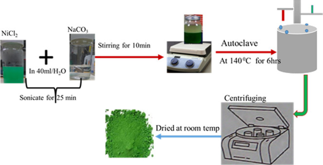
Synthesis process of Ni(OH)2.
2.3. Synthesis of TOCNF and Polypyrrole
At first, the TOCNF solution (0.4 wt %, 15 mL) appears to be a gel that was taken (poured) into a Petri dish and dried completely in an oven at 40 °C. The dried TOCNF film should be cut (2 × 2 cm2), then pyrrole monomers should be dropped on it (120 μL). The TOCNF film should then be shaken for 3 min while being turned over in the ice bath. Ammonium persulfate (APS, 204 mg) was dissolved in hydrochloric acid and then polymerized in situ (7 mL, 1 M). In order to add these solutions dropwise to the TOCNF@polypyrrole film (TOCNF@PPy) (see in Figure 2) that was in an ice bath, the mixture was kept in place for 3 h to allow for the reaction to occur. After the reaction, the film was rinsed with water and ethanol to remove the extra compound and finally dried in air.
Figure 2.
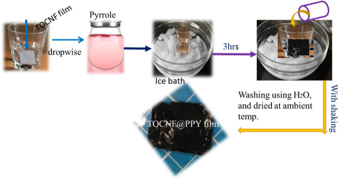
Preparation of TOCNF@PPy film.
2.4. Synthesis of NiO NPs and NiONPs@C-Dots
The calcination method was used for the synthesis of NiO NPs.42 C-dots were synthesized by the hydrothermal method.43 C-dots at an EDA/CA molar ratio of 1:1 were dispersed in water under 15 min sonication. Separately, NiO NPs were dispersed in water and sonicated for 15 min. Then, the two dispersions were mixed and stirred. The solid was collected by centrifugation, washed, and then dried in a vacuum oven at 40 °C for 3 h.
2.5. Measurement and Assembly of the Electrode for DSSCs
The TOCNF-Ni(OH)2/NiONP and TOCNF-Ni(OH)2/NiONP@C-dot films that were created for the WE in DSSCs. These films were dried at room temperature before being cut into (2 × 2 cm2). N719 dye (40 μL, 5 mM in ethanol) was applied to the (1 × 1 cm2 film region and allowed to dry for 15 min at room temperature before being used as the WE to absorb light. As a CE of TOCNF-PPy film 2 × 2 cm2 was also prepared. As a result, the CE of TOCNF-PPy film and WE of TOCNF-Ni(OH)2/NiONP or TOCNF-Ni(OH)2/NiONP@C-dot films have been assembled together. Redox electrolytes were injected (filled) in the area of 0.3 M KI, 0.05 M I2, and 10 mL of acetone nitrate solvent (1 × 1 cm2). The J–V curve for DSSC measurement was completed using a blue (430 nm) light source of a light-emitting diode.
3. Results and Discussion
3.1. Structural and Surface Morphology of NiONPs and NiONPs@C-Dots
The X-ray diffraction (XRD) curve for NiONPs and NiONPs@C-dots are shown in Figure 3. The peaks and the peak positions are in relatively good agreement with the previously reported cubic phase structure of NiO NPs, which correspond to the wurtzite structure of NiO. The peak positions appearing in the XRD curve can be readily indexed as (111), (200), (220), (311), (222), and (300) crystal planes of the bulk NiO, respectively. All these diffraction peaks can be perfectly indexed to the face-centered cubic (FCC) crystalline structure of NiO, not only in the peak position but also in their relative intensity of the characteristic peaks, which is in accordance with that of the standard spectrum (JCPDS, no. 04-0835). The XRD pattern shows that the samples are single phase and no other impurity distinct diffraction peak except the characteristic peaks of FCC phase NiO was detected. This result shows that the physical phases of the NiO NPs have higher purity prepared in this work. More insights on the information about the electronic structure and composition of nickel (Ni), oxygen (O), and carbon (c) are obtained by XPS analysis, which is shown in Figure 3b. Wide XPS survey spectra reveal the presence of Ni and O in NiO samples, while Ni, O, and C in the NiO@c-dot sample. The high-resolution and de-convoluted peaks of Ni 2p are shown in Figure 3c. Characteristic Ni 2p (Ni 2p3/2 and Ni 2p1/2) peaks appeared at strong twin peaks, which are corresponding to Ni–O and Ni–OH bonds, respectively.44,45 The high-resolution O 1S peak is shown in Figure 3d. The O 1S peak is de-convoluted in three peaks. The first one (O1) is observed at 529.3 eV, which is associated with Ni–O. The second peak (O2) is recorded at 531.2 eV, which is due to Ni–OH/C=O. The O3 peak is observed at 533 eV, which is attributed to [OH(H2O)/C–OH].46
Figure 3.

(a) XRD curve of NiO NPs and NiO NPs@c-dot NPs, (b) XPS survey of NiO NPs and NiO NPs@c-dot NPs, (c) high-resolution curve of Ni 2P peaks, and (d) high-resolution curve of O 1S peak.
The representative transmission electron microscopy (TEM) images of NiO NPs and NiO@c-dots are shown in Figure 4a,b, respectively. TEM analysis of the products provided information on the size and morphology of NiO NPs and their state of agglomeration. It can be seen from Figure 4a that the NiO NPs had spherical shapes and were well dispersed with a smooth surface and uniform size. Few small particles aggregate into secondary particles because of their extremely small dimensions and high surface energy. SEM images of NiO NPs and NiO@c-dots NPs are shown in Figure 4c,d, respectively. As revealed in Figure 4d, the SEM image of NiO NPs@c-dot NPs has similar morphology with of NiO NPs, which was assigned to by addition of C-dots the morphology of NiO NP has been not influenced.
Figure 4.
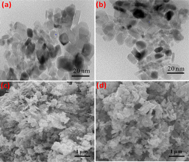
(a) TEM image of NiO NPs, (b) TEM image of NiO NPs@c-dots, (c) SEM image of NiO NPs, and (d) SEM image of NiO NPs@c-dots NPs.
3.2. BET Analysis NiONPs and NiONPs@C-Dots
Nitrogen (N2) adsorption–desorption isotherms of NiO NPs and NiONPs@C-dots are shown in Figure 5a. The specific surface area was analyzed using the Brunauer–Emmett–Teller (BET) method and the pore diameter and volume were determined using the Barrett–Joyner–Halenda method. Pore size distributions (PSD) of NiO NPs and NiONPs@C-dots are shown in Figure 5b. The BET parameters (in m2/g, nm, and cm3/g) obtained from N2 adsorption and desorption have been evaluated at 77 K. The surface area of NiO@C-dots was higher than that of NiO, in the P/P0 range at 56.65 and 32.31 m2/g, respectively, whereas the pore sizes obtained were 9.93 and 21.38 nm, for NiONPs@C-dots and NiO NPs, respectively. As a result, the aforementioned PSD indicates that the NiO NP layer are mesoporous. The appearance of the adsorption hysteresis loop is compatible with the IV (a) type curve. This hysteresis loop type represents the pore structure of the adsorbent. Its hysteresis loops are of type H3. It is indicated that it is made of mesoporous materials. The pore sizes of NiONPs@C-dots and NiO NPs were observed to be 9.93 and 21.38 nm, respectively, which are consistent with the findings in TEM pictures.47,48 C-dots have a higher surface area than metal oxides due to its particle size being less than 10 nm. This means for a particle size being reduced, a surface area would have been high. The high surface area was more effective to accumulate and keep the charge-absorbed light.
Figure 5.

(a) N2 adsorption–desorption isotherms of NiONPs@C-dots and (b) PSD dV/d(logD) (red for NiONPs@C-dots, black for NiO NPs).
3.3. Fourier-Transform Infrared Spectroscopy
Infrared absorption spectra were obtained and analyzed to recognize the portion of molecules/functional groups of the TOCNF, Ni(OH)2, TOCNF/Ni(OH)2@NiONPs, and TOCNF/Ni(OH)2/NiO NP@C-dots. The Fourier-transform infrared (FTIR) spectrum of pulp (TOCNF) has been shown in Figure 6 and Table 1. A characteristic absorption band of the O–H stretching mode of vibration at 3462 cm–1 and C–H (stretching) at 3928 cm–1, while antisymmetric and symmetric COO– stretching appeared at 1614 and 1398 cm–1, respectively. Furthermore, the band appearing at 1150 cm–1 was attributed to C–O–C stretching.49 Both 1614 and 1398 cm–1 confirmed the new introduction of the carboxylate group after the oxidation of pulp. Three Ni(OH)2 peaks have appeared at 3392, 1624, and 447 cm–1, which have been attributed to O–H (stretching), O–H (bending), and Ni–O (stretching). The original peaks of Ni(OH)2 and TOCNF have appeared in correspondence with the TOCNF/Ni(OH)2@NiONPs and TOCNF/Ni(OH)2/NiONP@C-dot film. Thus, the reaction between TOCNF and Ni(OH)2 has confirmed, which is a vital issue to make more wires. However, the new absorption band does not appear after the TOCNF, and the Ni(OH)2 were composed together.
Figure 6.
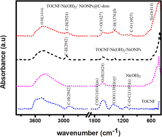
FTIR curve of TOCNF, Ni(OH)2, TOCNF-Ni(OH)2/NiONPs, and TOCNF/Ni(OH)2/NiONPs@C-dots.
Table 1. FTIR Absorption Bands of TOCNF, Ni(OH)2, TOCNF/Ni(OH)2 @NiONP, and TOCNF Ni(OH)2/NiONP@C-Dotsa.
| assignment and peak distribution | Ni(OH)2 | TOCNF/Ni(OH)2@NiONP | TOCNF/Ni(OH)2/NiONP@C-dots | TOCNF |
|---|---|---|---|---|
| O–H(s) | 3392 | 3424 | 3434 | 3462 |
| C–H, (s) | 2942 | 2923 | 2928 | |
| O–H | 1623(b) | 1621 | 1627 | 1614 |
| C=O(s) | C=O(s) | COO–(γ) | ||
| C–H(b) | 1374.99 | 1376 | 1398 | |
| COO– (δ) | ||||
| C–O(s) | 1024 | 1025 | 1149 | |
| C–O–C (s) | ||||
| Ni–O(S) | 447 | 420 | 414 | |
Stretching = s; antisymmetric stretching = γ; symmetric stretching = δ; bending = b.
3.4. CNF Film Surface Treated Using Octadecylamine
Basically, when octadecylamine (ODA) was applied onto TEMPO-CNFs, it resulted in higher thermal stability and reduced residue from the CNF. It can convert the carboxyl group to an amidation group, which means it can change surface optical properties. To modify the surface of the CNF, first EDC (1.53 mg) and NHS (0.92 mg) were dissolved in 2 mL of DI water and stirred for 20 min at room temperature. Simultaneously, ODA (2.2 mg) was dissolved in 2 mL of isopropyl alcohol and then stirred for 20 min. The dried CNF film (2 × 2 cm2) was cut and dipped in the solution of EDC and NHS after 1 hr. The CNF film was washed to remove excess amount of EDC and NHS. Continuously, the ODA solution was added dropwise on the CNF film treated by EDC and NHS and was kept for 3 h. After the completion of the reaction, the film was washed by isopropyl alcohol and then dried at room temperature. The hydrophobicity of the modified CNF film was confirmed via the contact angle measurement using eq 1, and it is demonstrated in Figure 7. Thus, at different weights of ODA, a higher contact angle was revealed at 3.3 mg of ODA, which is attributed to the good hydrophobicity.
| 1 |
Figure 7.

Contact angle of modified CNF at d/t weight of ODA (A) 2.2, (B) 3.3, and (C) 4.4 mg.
3.5. Photoelectrochemical Performance Measurement
Photoelectrochemical assessment is a reliable mechanism to explore the effectiveness of electron and hole charge separation. Also, to investigate the properties of charge transfer, the transient photocurrent response has been accomplished for the DSSC based on the CNF/Ni(OH)2 substrate for the flexible electrode. Typically, it performs visible light irradiation to study the materials’ charge-transfer properties, and the results obtained are shown in Figure 8A. The photocurrent response of different substrates has been measured and revealed in Figure 8A(a). First, using the 2.948 M/12.5 g concentration of sodium carbonate (Na2CO3) with the different masses of nickel chloride (0.2, 0.3, 0.387, 0.442, 0.5, and 0.6 g) and 15 mL CNF film, the transient photocurrent responses have been investigated to have further evidence for the photocurrent response mechanism/behavior. The CNF@Ni(OH)2 film with Na2CO3 (12.5 g) and NiCl2 (0.387 g) shows higher transient-photocurrent responses than the other, which shows good photoconducting behavior of the semiconductors. Therefore, the CNF@Ni(OH)2-prepared electrode can be attributed to the incorporation of NiONP and NiONP@C-dots, which are known for their semiconductor behavior. But, after the surface modification of CNF was done via the mediated ODA system, the photocurrent response of a CNF modified with different contents of ODA (2.2, 3.3, and 4.4 mg) were revealed with a different result. It suggested that when the carboxyl functional group of CNF is transferred to the amidation functional group due to the ODA effect, it influences the surface and optical properties of the CNF. Thus, the photocurrent response of unmodified CNF film has increased two times, as revealed in Figure 8B,B(a), which will have also been expected to enhance the power conversion efficiency (PCE) of unmodified CNF substrates. The lower photocurrent response of CNF@Ni(OH)2 substrate and CNFmod/ITO NP suggested that it has lower light harvesting abilities and less charge separation because of its transmittance and smoothness being lower than that of ITO/glass or ITO/PET substrates.
Figure 8.

Transient photocurrent responses of (A) CNF@Ni(OH)2 film at the different masses of nickel chloride (NiCl2, as the precursor) (B). CNFmod/ITO NP at different weights of ODA (a) 2.2, (b) 3.3, and (c) 4.4 mg.
As shown from the CV curve in Figure 9a, the conductivity of the composite film consisting of PPy and TOCNF conductive polymers was tested and had a maximum current of 1.84 mA/cm2 at the potential window between −0.6 and 1 V, which has a remarkable replacement of Pt electrode after modification. The different concentrations of pyrrole also influenced the conductivity of the conductive polymer, as seen in Figure 9b. The 200 μL is effective when added to TOCNFs to increase the conductivity of the TOCNF/polypyrrole (PPY). As a result, after the modification of PPY conducting polymer by the TOCNF film, the possibility to prepare a flexible CE for photoelectrochemical applications in DSSCs has been confirmed. The Nyquist plot of electrochemical performance was carried out at 10 mV of amplitude and 1–100 Hz range of frequency, as revealed in Figure 9c. The numerical values of charge-transfer resistance (Rct) of NiO NW and Ni(OH)2 were founded 23.02 and 24.3Ω, respectively, which was coated on the ITO glass. As seen from the below result, the charge-transfer resistance of Ni(OH)2 is almost the same as NiONW on the ITO glass substrate. Therefore, the result recommended that Ni(OH)2 has semiconductive characteristics. On the other hand, the TOCNF/Ni(OH)2 substrate was evaluated for its charge-transfer resistance as a substrate of a WE for DSSCs instead of ITO glass; after NiO NP and NiONP@C-dots have been deposited on, the charge-transfer resistances obtained were found to be 43.51 Ω and 32.03, respectively (see in Figure 9d. However, the charge-transfer resistance of NiONP was found to be 21.45 Ω for the nonflexible electrode system based on ITO glass. Comparatively, the charge transfer of TOCNF/Ni(OH)2 was 1.5 times higher than that of NiONPs based on the ITO glass substrate, suggesting that higher charge-transfer resistance decreases the conductivities of the electrode because it is assumed that the TOCNF film is a complete insulator. This factor may have lowered the PCE of the NiONP based on the TOCNF/Ni(OH)2 flexible substrate.
Figure 9.

CV measurement of (a) TOCNF/PPY(120 μLPy), (b) TOCNF/PPY at different microliter (μL) of pyrrole (PY), (c) Nyquist plots of EIS of Ni (OH)2 (green on ITO glass) and NiONW (red on ITO glass), and (d) Nyquist plots of EIS CNF@Ni(OH)2/NiO NP film (red) CNF@Ni(OH)2/NiO NP@C-dot film (black).
3.6. Current–Voltage Measurement Performance of DSSC
The ITO-free flexible WE consisting of a composite of TOCNF/Ni(OH)2 substrate for photovoltaic properties of DSSCs has directly been tested to assess its PCE (η). As displayed in Figure 10, the highest performance of PCE of the TOCNF/Ni(OH)2@NiO NPs was evaluated to be 0.197% when different mass amounts of NiO NPs have been deposited on the TOCNF/Ni(OH)2 substrate. The TOCNF/Ni(OH)2@NiO NPs of the J–V curve as the photocathode has resulted in the maximum 0.126 mA ± 0.03/cm2 of short circuit current density (Jsc), 0.456 V of the open circuit potential (Voc), and 0.344% fill factor (FF). Almost, the obtained performance of PCE of TOCNF/Ni(OH)2@NiO NPs for the flexible electrode is very low when compared to the value of NiO NPs, which were deposited on ITO glass. Because the TOCNF/Ni(OH)2@NiO NPs show a small light-photocurrent conversion and higher charge-transfer resistance, it implied that Ni(OH)2 is more remarkable for the transfer of charges in the process of TOCNF/Ni(OH)2.
Figure 10.

J–V curve of DSSC performance at d/t concentration of Na2CO3 in the (TOCNF-Ni(OH)2/NiONP@C-dots) film.
Moreover, our current results 1.3% PCE is very competitive compared with the recently reported output of NiO NPs based on ITO glass.24,25 Therefore, it is recommended that a flexible electrode prepared from the composite of TOCNF/Ni(OH)2 substrates is available for DSSCs as the WE. As shown in Figure 11 and Table 2, the parameters of DSSC, Isc, Voc, and PCE (η %), have been demonstrated and calculated, respectively. The PCE obtained for NiO NP and NiO NP@C-dots were 0.22 and 1.45% when using CNF/Ni(HO)2 as the substrate.
Figure 11.
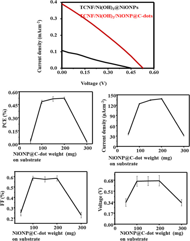
DSSC performance of NiO NPs (blue) and NiO NPs@C-dots (red) based on the CNF/Ni(HO)2 substrate.
Table 2. DSSC Performance of NiO NP@C-Dots Based on the CNF/Ni(HO)2 Substrate as the Photocathode at Different wt % of NiONP@C-Dots.
| NiONP@C-dots (wt %) | Jsc (mA cm–2) | Vov (V) | FF | η % |
|---|---|---|---|---|
| 0 | 0.480 + 0.04 | 0.460 + 0.02 | 0.342 + 0.04 | 0.75 + 0.02 |
| 15 | 0.574 + 0.02 | 0.495 + 0.04 | 0.439 + 0.04 | 1.247 + 0.04 |
| 25 | 0.576 + 0.02 | 0.501 + 0.05 | 0.440 + 0.02 | 1.27 + 0.03 |
| 30 | 0.575 + 0.01 | 0.500 + 0.04 | 0.450 + 0.01 | 1.30 + 0.10 |
| 50 | 0.526 + 0.05 | 0.501 + 0.01 | 0.409 + 0.03 | 1.07 + 0.03 |
| 75 | 0.480 + 0.04 | 0.473 + 0.02 | 0.341 + 0.04 | 0.77 + 0.02 |
| 85 | 0.119 + 0.03 | 0.353 + 0.04 | 0.310 + 0.02 | 0.13 + 0.04 |
The PCE of NiO NPs was synergistically increased when the C-dot was added. It was clearly discussed in our earlier work. It was suggested that the C-dot could improve the PCE of the DSSC by facilitating charge separation, which would increase the performance of the solar cell.
However, DSSC’s PCE utilized a flexible electrode, ITO/PET is typically smaller than that based on a non-flexible electrode, and the p-type PCE based on ITO/PET DSSCs is especially smaller than that of based on n-type ITO/PET DSSCs. DSSCs with a non-flexible electrode are still significantly different from the DSSC with flexible electrodes.
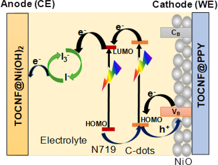
Scheme 1 depicts a p-type DSSC in detail, with the WE (cathode) being made of Ni(OH)2@TOCNF/NiONPs/C-dot/dye elements. The electrons are excited from the ground-state highest occupied molecular orbital (HOMO) to lowest unoccupied molecular orbital (LUMO) when visible light is shone on a sensitizer (LUMO). The sensitizer then introduces an electron generated into the electrolytes, where it undergoes a redox reaction between electrolytes (I3–/I–), moving from the CE (anode) to the WE (cathode) via an open load. The N-doped in the C-dots generates the creation of a new surface energy state which is assigned to boost the performance of DSSCs.33
Scheme 1. Representation of NiO@C-Dots@N719 Photovoltaic Cells.

The PCE value of the substrate-based NiO(OH)2/TOCNF film WEs was 1.3% (see Table 3). This value was greater than the WEs made of PET at 0.45%. In addition, the 1.3% PCE of the NiO@C-dot-based NiO(OH)2/TOCNF film substrate was nearly identical to that of the corresponding flexible FDSSCs using a commercial ITO/PEN film. However, as illustrated in Table 3, the Ni(OH)2/TOCNF-based flexible substrate used in flexible solar cells is less effective than the ITO/PET film substrate and therefore, further development is anticipated. The PCE of these FDSSC is nearly identical to the recently reported PEC value of 1.31% ITO/PET-based substrate by Zhang and Konno.29,51
Table 3. Photovoltaic Efficiencies of Flexible DSSCs Made of Various Materials Are Compared.
4. Conclusions
A flexible electrode from CNF/Ni(OH)2 and CNF@PPY substrates as the WE and CE was successfully prepared using the simple method. These electrodes established for DSSCs with CNF/Ni(OH)2 as a substrate of a WE and CNF@PPY as a CE mounted together have obtained 0.75% PCE with the NiO NP semiconductor. Though, its PCE has increased from 0.75 to 1.3% once the C-dots were added to NiO NP and has been deposited on the CNF/Ni(OH)2 substrate, respectively, using a sensitizer (N719, 20 μL). The result is significantly improved to 1.3% after the C-dot (12.5 wt %). Nevertheless, the CNF/Ni(OH)2 PCE substrate based on flexible solar cells is considerably lower than that of the ITO/PET flexible electrode because we cannot fully regulate its thickness, uniformity, and transparency. So that it has resisted the generation of photocurrent density, which can reduce DSSC PCE performance. Nevertheless, it has revealed encouraging outcomes for FDSSCs. The newly discovered TOCNF/Ni(OH)2 substrate has been investigated for FDSSC electrodes.
Acknowledgments
The writers would like to express their sincere gratitude to the University of Dambi Dollo, Walter Sisulu University (WSU), the National Research Foundation of South Africa (NRF), ESKOM and the Organization for the Prohibition of Chemical Weapons (OPCW) for financial support.
The authors declare no competing financial interest.
References
- Nezhnikova E.; Papelniuk O.; Dudin M. Developing renewable and alternative energy sources to improve the efficiency of housing construction and management. Int. J. Energy Econ. Pol. 2019, 9, 172–178. 10.32479/ijeep.7732. [DOI] [Google Scholar]
- Azam W.; Khan I.; Ali S. A. Alternative energy and natural resources in determining environmental sustainability: a look at the role of government final consumption expenditures in France. Environ. Sci. Pollut. Res. 2023, 30, 1949–1965. 10.1007/s11356-022-22334-z. [DOI] [PMC free article] [PubMed] [Google Scholar]
- Salvarli M. S.; Salvarli H.. For sustainable development: future trends in renewable energy and enabling technologies. In Renewable Energy-Resources, Challenges and Applications; IntechOpen, 2020. [Google Scholar]
- Zhao J.; Burke A. F. Review on supercapacitors: Technologies and performance evaluation. J. Energy Chem. 2021, 59, 276–291. 10.1016/j.jechem.2020.11.013. [DOI] [Google Scholar]
- Shaari N.; Kamarudin S. K.; Bahru R. Carbon and graphene quantum dots in fuel cell application: An overview. Int. J. Energy Res. 2021, 45, 1396–1424. 10.1002/er.5889. [DOI] [Google Scholar]
- Tucho B. G.; Etefa H. F.; Kumar V.; Raba G. A.; Efa M. T.; Dejene F. B. Effect of wood moisture content on the performance of wood burning cook stoves. Int. J. Sustain. Eng. 2023, 16, 1–10. 10.1080/19397038.2022.2159568. [DOI] [Google Scholar]
- Zheng Z.; Liang W.; Lin R.; Hu Z.; Wang Y.; Lu H.; Zhong W.; Shen S.; Pan Y. Facile Synthesis of Zinc Indium Oxide Nanofibers Distributed with Low Content of Silver for Superior Antibacterial Activity. Small Struct. 2022, 4, 2200291. 10.1002/sstr.202200291. [DOI] [Google Scholar]
- Wang Z.; Shen S.; Lin Z.; Tao W.; Zhang Q.; Meng F.; Gu L.; Zhong W. Regulating the local spin state and band structure in Ni3S2 nanosheet for improved oxygen evolution activity. Adv. Funct. Mater. 2022, 32, 2112832. 10.1002/adfm.202112832. [DOI] [Google Scholar]
- Lin Z.; Xiao B.; Huang M.; Yan L.; Wang Z.; Huang Y.; Shen S.; Zhang Q.; Gu L.; Zhong W. Realizing Negatively Charged Metal Atoms through Controllable d Electron Transfer in Ternary Ir1– xRhxSb Intermetallic Alloy for Hydrogen Evolution Reaction. Adv. Energy Mater. 2022, 12, 2200855. 10.1002/aenm.202200855. [DOI] [Google Scholar]
- Enríquez E.; Mariscal A.; Serna R.; Fernández J. Transparent high conductive Titanium oxynitride nanofilms obtained by nucleation control for sustainable optolectronics. Appl. Surf. Sci. 2022, 574, 151631. 10.1016/j.apsusc.2021.151631. [DOI] [Google Scholar]
- Li X.; Li P.; Wu Z.; Luo D.; Yu H.-Y.; Lu Z.-H. Review and perspective of materials for flexible solar cells. Mater. Rep.: Energy 2021, 1, 100001. 10.1016/j.matre.2020.09.001. [DOI] [Google Scholar]
- Sharma A.; Masoumi S.; Gedefaw D.; O’Shaughnessy S.; Baran D.; Pakdel A. Flexible solar and thermal energy conversion devices: Organic photovoltaics (OPVs), organic thermoelectric generators (OTEGs) and hybrid PV-TEG systems. Appl. Mater. Today 2022, 29, 101614. 10.1016/j.apmt.2022.101614. [DOI] [Google Scholar]
- Mercadillo V. O.; Chan K. C.; Caironi M.; Athanassiou A.; Kinloch I. A.; Bissett M.; Cataldi P. Electrically Conductive 2D Material Coatings for Flexible and Stretchable Electronics: A Comparative Review of Graphenes and MXenes. Adv. Funct. Mater. 2022, 32, 2204772. 10.1002/adfm.202204772. [DOI] [Google Scholar]
- Xue Z.; Liu X.; Zhang N.; Chen H.; Zheng X.; Wang H.; Guo X. High-performance NiO/Ag/NiO transparent electrodes for flexible organic photovoltaic cells. ACS Appl. Mater. Interfaces 2014, 6, 16403–16408. 10.1021/am504806k. [DOI] [PubMed] [Google Scholar]
- Leyrer J.; Hunter R.; Rubilar M.; Pavez B.; Morales E.; Torres S. Development of dye-sensitized solar cells based on naturally extracted dye from the maqui berry (Aristotelia chilensis). Opt. Mater. 2016, 60, 411–417. 10.1016/j.optmat.2016.08.021. [DOI] [Google Scholar]
- Gonçalves B. F.; Botelho G.; Lanceros-Méndez S.; Kolen’ko Y. V. Eco-friendly and cost-efficient inks for screen-printed fabrication of copper indium gallium diselenide photoabsorber thin films. J. Colloid Interface Sci. 2021, 598, 388–397. 10.1016/j.jcis.2021.04.059. [DOI] [PubMed] [Google Scholar]
- Devadiga D.; Selvakumar M.; Shetty P.; Santosh M. S. The integration of flexible dye-sensitized solar cells and storage devices towards wearable self-charging power systems: A review. Renew. Sustain. Energy Rev. 2022, 159, 112252. 10.1016/j.rser.2022.112252. [DOI] [Google Scholar]
- Noorasid N.; Arith F.; Mustafa A.; Azam M.; Mahalingam S.; Chelvanathan P.; Amin N. Current advancement of flexible dye sensitized solar cell: A review. Optik 2022, 254, 168089. 10.1016/j.ijleo.2021.168089. [DOI] [Google Scholar]
- Singh S. S.; Shougaijam B.. Recent Development and Future Prospects of Rigid and Flexible Dye-Sensitized Solar Cell: A Review. In Contemporary Trends in Semiconductor Devices. Lecture Notes in Electrical Engineering, Vol 850; Goswami R., Saha R., Eds.; Springer: Singapore, 2022. https://doi.org/10.1007/978-981-16-9124-9_5. [Google Scholar]
- Gupta P. K.; Raghunath S. S.; Prasanna D. V.; Venkat P.; Shree V.; Chithananthan C.; Choudhary S.; Surender K.; Geetha K. An Update on Overview of Cellulose, Its Structure and Applications. Cellulose 2019, 201, 84727. [Google Scholar]
- Li T.; Chen C.; Brozena A. H.; Zhu J.; Xu L.; Driemeier C.; Dai J.; Rojas O. J.; Isogai A.; Wågberg L.; et al. Developing fibrillated cellulose as a sustainable technological material. Nature 2021, 590, 47–56. 10.1038/s41586-020-03167-7. [DOI] [PubMed] [Google Scholar]
- Kim J.Nanocellulose-based paper actuators. In Nanocellulose Based Composites for Electronics; Thomas S., Ed.; 2021; pp 163−183. https://doi.org/10.1016/B978-0-12-822350-5.00007-2. [Google Scholar]
- Wan C.; Jiao Y.; Li J. Flexible, highly conductive, and free-standing reduced graphene oxide/polypyrrole/cellulose hybrid papers for supercapacitor electrodes. J. Mater. Chem. A 2017, 5, 3819–3831. 10.1039/c6ta04844g. [DOI] [Google Scholar]
- Shokri J.; Adibkia K.. Application of cellulose and cellulose derivatives in pharmaceutical industries. In Cellulose-medical, pharmaceutical and electronic applications; IntechOpen, 2013. [Google Scholar]
- Mun S.; Chen Y.; Kim J. Cellulose–titanium dioxide–multiwalled carbon nanotube hybrid nanocomposite and its ammonia gas sensing properties at room temperature. Sens. Actuators, B 2012, 171, 1186–1191. 10.1016/j.snb.2012.06.066. [DOI] [Google Scholar]
- Luo J.; Xing Y.; Sun C.; Fan L.; Shi H.; Zhang Q.; Li Y.; Hou C.; Wang H. A bio-adhesive ion-conducting organohydrogel as a high-performance non-invasive interface for bioelectronics. Chem. Eng. J. 2022, 427, 130886. 10.1016/j.cej.2021.130886. [DOI] [Google Scholar]
- Farooq A.; Li M.; Alasood A.; Farooq A.; Ashraf M.; Patoary M. K.; Liu L. Novel pretreatment performance evaluation for cellulose nanofibrils extraction from Ficus natalensis barkcloth. J. Polym. Environ. 2022, 30, 1547–1559. 10.1007/s10924-021-02297-x. [DOI] [Google Scholar]
- Li G.; Sheng L.; Li T.; Hu J.; Li P.; Wang K. Engineering flexible dye-sensitized solar cells for portable electronics. Sol. Energy 2019, 177, 80–98. 10.1016/j.solener.2018.11.017. [DOI] [Google Scholar]
- Gemeda G. F.; Etefa H. F.; Hsieh C.-C.; Kebede M. A.; Imae T.; Yen Y.-W. Preparation of ZnO/NiO-loaded flexible cellulose nanofiber film electrodes and their application to dye-sensitized solar cells. Carbohydr. Polym. Technol. Appl. 2022, 3, 100213. 10.1016/j.carpta.2022.100213. [DOI] [Google Scholar]
- Gupta P. K.; Raghunath S. S.; Prasanna D. V.; Venkat P.; Shree V.; Chithananthan C.; Choudhary S.; Surender K.; Geetha K. An update on overview of cellulose, its structure and applications. Cellulose 2019, 201, 84727. [Google Scholar]
- Do T. T. A.; Grijalvo S.; Imae T.; Garcia-Celma M. J.; Rodríguez-Abreu C. A nanocellulose-based platform towards targeted chemo-photodynamic/photothermal cancer therapy. Carbohydr. Polym. 2021, 270, 118366. 10.1016/j.carbpol.2021.118366. [DOI] [PubMed] [Google Scholar]
- Li J.; Liu D.; Li J.; Yang F.; Sui G.; Dong Y. Fabrication and Properties of Tree-Branched Cellulose Nanofibers (CNFs) via Acid Hydrolysis Assisted with Pre-Disintegration Treatment. Nanomaterials 2022, 12, 2089. 10.3390/nano12122089. [DOI] [PMC free article] [PubMed] [Google Scholar]
- Etefa H. F.; Imae T.; Yanagida M. Enhanced photosensitization by carbon dots Co-adsorbing with dye on p-type semiconductor (Nickel Oxide) solar cells. ACS Appl. Mater. Interfaces 2020, 12, 18596–18608. 10.1021/acsami.0c02413. [DOI] [PubMed] [Google Scholar]
- Kamil A. F.; Abdullah H. I.; Rheima A. M.; Mohammed S. H. Impact of Fe2NiO4 nanoparticles to increase efficiency of dye-sensitized solar cells. Mater. Today: Proc. 2022, 49, 2727–2732. 10.1016/j.matpr.2021.09.253. [DOI] [Google Scholar]
- Dao V.-D.; Dang H.-L. T.; Vu N. H.; Vu H. H. T.; Hoa N. D.; Hieu N. V.; Tuan P. A. Nanoporous NiO nanosheets-based nanohybrid catalyst for efficient reduction of triiodide ions. Sol. Energy 2020, 197, 546–552. 10.1016/j.solener.2020.01.037. [DOI] [Google Scholar]
- Nemera D. J.; Etefa H. F.; Kumar V.; Dejene F. B. Hybridization of nickel oxide nanoparticles with carbon dots and its application for antibacterial activities. Luminescence 2022, 37, 965–970. 10.1002/bio.4241. [DOI] [PubMed] [Google Scholar]
- Joshi B.; Samuel E.; Kim Y.-i.; Yarin A. L.; Swihart M. T.; Yoon S. S. Progress and potential of electrospinning-derived substrate-free and binder-free lithium-ion battery electrodes. Chem. Eng. J. 2022, 430, 132876. 10.1016/j.cej.2021.132876. [DOI] [Google Scholar]
- Uusi-Tarkka E.-K.; Levanič J.; Heräjärvi H.; Kadi N.; Skrifvars M.; Haapala A. All-Cellulose Composite Laminates Made from Wood-Based Textiles: Effects of Process Conditions and the Addition of TEMPO-Oxidized Nanocellulose. Polymers 2022, 14, 3959. 10.3390/polym14193959. [DOI] [PMC free article] [PubMed] [Google Scholar]
- Khadraoui M.; Khiari R.; Brosse N.; Bergaoui L.; Mauret E. Combination of steam explosion and TEMPO-mediated oxidation as pretreatments to produce nanofibril of cellulose from Posidonia oceanica bleached fibres. Bioresources 2022, 17, 2933–2958. 10.15376/biores.17.2.2933-2958. [DOI] [Google Scholar]
- Nguyen K.; Hoa N. D.; Hung C. M.; Le D. T. T.; Van Duy N.; Van Hieu N. A comparative study on the electrochemical properties of nanoporous nickel oxide nanowires and nanosheets prepared by a hydrothermal method. RSC Adv. 2018, 8, 19449–19455. 10.1039/c8ra02862a. [DOI] [PMC free article] [PubMed] [Google Scholar]
- Ahmed R.; Nabi G.; Ali F.; Naseem F.; Isa Khan M.; Iqbal T.; Tanveer M.; Ali W.; Ali W.; Arshad N. S.; et al. Controlled growth of Mo-Doped NiO nanowires with enhanced electrochemical performance for supercapacitor applications. Mater. Sci. Eng., B 2022, 284, 115881. 10.1016/j.mseb.2022.115881. [DOI] [Google Scholar]
- Varunkumar K.; Hussain R.; Hegde G.; Ethiraj A. S. Effect of calcination temperature on Cu doped NiO nanoparticles prepared via wet-chemical method: structural, optical and morphological studies. Mater. Sci. Semicond. Process. 2017, 66, 149–156. 10.1016/j.mssp.2017.04.009. [DOI] [Google Scholar]
- Prasannan A.; Imae T. One-pot synthesis of fluorescent carbon dots from orange waste peels. Ind. Eng. Chem. Res. 2013, 52, 15673–15678. 10.1021/ie402421s. [DOI] [Google Scholar]
- Liu W.; Lu C.; Wang X.; Liang K.; Tay B. K. In situ fabrication of three-dimensional, ultrathin graphite/carbon nanotube/NiO composite as binder-free electrode for high-performance energy storage. J. Mater. Chem. A 2015, 3, 624–633. 10.1039/c4ta04023f. [DOI] [Google Scholar]
- Mular A.; Shanzer A.; Kozłowski H.; Hubmann I.; Misslinger M.; Krzywik J.; Decristoforo C.; Gumienna-Kontecka E. Cyclic analogs of desferrioxamine e siderophore for 68Ga nuclear imaging: Coordination chemistry and biological activity in staphylococcus aureus. Inorg. Chem. 2021, 60, 17846–17857. 10.1021/acs.inorgchem.1c02453. [DOI] [PMC free article] [PubMed] [Google Scholar]
- Wang H.-q.; Fan X.-p.; Zhang X.-h.; Huang Y.-g.; Wu Q.; Pan Q.-c.; Li Q.-y. In situ growth of NiO nanoparticles on carbon paper as a cathode for rechargeable Li–O 2 batteries. RSC Adv. 2017, 7, 23328–23333. 10.1039/c7ra02932b. [DOI] [Google Scholar]
- Ramimoghadam D.; Hussein M. Z. B.; Taufiq-Yap Y. H. Synthesis and characterization of ZnO nanostructures using palm olein as biotemplate. Chem. Cent. J. 2013, 7, 71. 10.1186/1752-153x-7-71. [DOI] [PMC free article] [PubMed] [Google Scholar]
- Erika D.; Erika D.; Mardiana S.; Rasrendra C. B.; Khalil M.; Kadja G. T. Nanocasting nanoporous nickel oxides from mesoporous silicas and their comparative catalytic applications for the reduction of p-nitrophenol. Chem. Phys. Lett. 2022, 803, 139809. 10.1016/j.cplett.2022.139809. [DOI] [Google Scholar]
- Liu C.-F.; Ren J.-L.; Xu F.; Liu J.-J.; Sun J.-X.; Sun R.-C. Isolation and characterization of cellulose obtained from ultrasonic irradiated sugarcane bagasse. J. Agric. Food Chem. 2006, 54, 5742–5748. 10.1021/jf060929o. [DOI] [PubMed] [Google Scholar]
- Atanacio-Sánchez X.; Pech-Rodríguez W.; Armendáriz-Mireles E.; Castillo-Robles J.; Meléndez-González P.; Rocha-Rangel E. Improving performance of ZnO flexible dye sensitized solar cell by incorporation of graphene oxide. Microsyst. Technol. 2020, 26, 3591–3599. 10.1007/s00542-020-04820-x. [DOI] [Google Scholar]
- Zhang L.; Konno A. Development of flexible dye-sensitized solar cell based on predyed zinc oxide nanoparticle. Int. J. Electrochem. Sci. 2018, 13, 344–352. 10.20964/2018.01.07. [DOI] [Google Scholar]