Abstract
Purpose:
The current study intended to provide a comparison of biomechanical behaviors of two different treatment concepts for full-mouth rehabilitation with dental implants placed according to the “All-on-four” concept and “All-on-six” concept with analysis of the stress patterns of the implant support system using three-dimensional finite element analysis (FEA).
Materials and Methods:
The edentulous mandible was treated with two different implant designs. “All-on-Four” implant placement concept was used in Model 1 with two central axial implants and two distally tilted implants at 17° and in Model 2, “All-on-Six” concept was applied with six vertically placed implants. Individual vertical and horizontal load of 100 N and oblique load of 141 N at 45° was applied to all implants. To evaluate and compare the results in terms of maximum principal stress, we used FEA.
Results:
All-on-six showed smaller maximum principal stress values on the cortical bone and implants. However, maximum principal stress values obtained on trabecular bone was smaller in the All-on-four design for vertical and horizontal loading conditions.
Conclusions:
The All-on-six approach showed more favorable biomechanical behavior.
Keywords: All-on-four, all-on-six, finite element analysis, maximum principal stress, tilted implants
INTRODUCTION
Dental implants in resorbed mandible often are inadequate to place with their length (>10 mm) because of the vicinity to inferior alveolar nerve in the posterior areas of atrophic mandible. Originally, Branemark had proposed fixed dental implant prosthesis on four and/or six implants for an edentulous mandible.[1] Studies with integrated tilted implants in between interforaminal region for compromised mandible optimize the anterior posterior spread of implants in a way avoidance of neurovascular bundle. This led to acceptance of popular concept of “All on Four “where there is angular placement of distal implants to avoid vital structures.[2] However, there are conflicting evidence with bone resorption and high stress concentration with cortical bone around tilted implants.[3-7] Marginal bone stability circling the dental implants is critical for its longevity and its loss will impact the treatment prognosis. The three-dimensional (3D) finite element method (FEM) is a numeric stimulation used for engineering analysis. Structural stresses, strains, and displacements can be verified when subjected to external and internal loads. Our study compared biomechanical behaviors around distally placed implants of two treatment concepts (all on four and all on six) with implant rehabilitation for moderately atrophic edentulous mandible.
MATERIALS AND METHODS
The study was designed in vitro to provide a comparison of biomechanical behaviors of two different treatment designs for full-mouth rehabilitation with dental implants. Before starting the study, approval was taken from the ethical committee of the university. The concept all on four and all on six for edentulous mandible and their stress patterns generated within the cortical and cancellous bone were analyzed with 3D finite element analysis (FEA).[8–10]
Model fabrication
From the patient’s computed tomography, an edentulous mandible was simulated that would be rehabilitated with full arch fixed dental implant prosthesis[11] [Figures 1 and 2]. MIMICS19.0 (Materialise, Leuven, Belgium), a medical imaging and editing program, was used to rebuild the 3D geometry of an edentulous mandible.[12] Semi-autonomic algorithm was applied along with region-growing algorithm to interpolate two-dimensional DICOM image data so as to regenerate the 3D model.[13] The anterior region of the mandible was remeshed with 0.5 mm triangle edge length[14] [Figure 3]. Local smoothing, removal of overlapping triangles, and fixing of bad edges were performed to effectively work the model in FEA. Nonuniform rational B-splines were used to patch surfaces and convert surface model into solid model of mandible[15] [Figure 4]. A 1.006-mm cortical bone layer was defined around the cancellous core[16] [Figure 5]. Implants were designed using the software creo parametric 5.0 student version. Dimensions were retrieved from the scientific literature and catalogs of the used implant in the patient (RAPID DENTIN-Dental Implants Technologies Ltd, Israel) [Figure 6]. Two cylindrical titanium abutments (3 mm high) with a straight profile were modeled and placed on the vertical implants, and 2 abutments angled at 17° were joined to the tilted implants for Model A. Model B had six vertical cylindrical titanium abutments for all the six implants. A rigid cobalt chromium 3 mm thick and 10 mm long, in the shape of an arc, was designed to serve as a framework joined to the implant abutments.[9] The final model represented a completely fixed prosthetic replacement for an edentulous mandible supported by 4 implants (Model A) according to the All-on-4 technique and 6 implants (Model B) [Figures 7-10 and Table 1].
Figure 1.
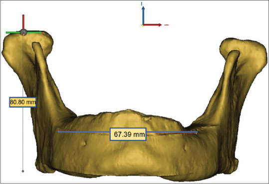
3D model with measurements (frontal view). 3D – Three-dimensional
Figure 2.
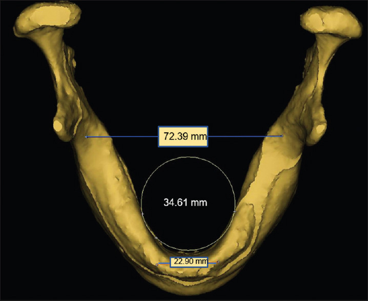
3D model with measurements (occlusal view). 3D – Three-dimensional
Figure 3.
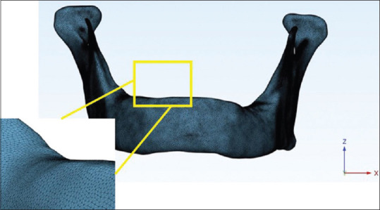
Adaptive remeshing
Figure 4.

Local smoothing, removal of overlapping triangles and fixing of bad edges
Figure 5.
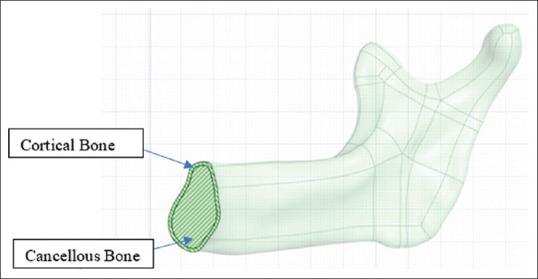
Model depicting cortical and cancellous bone
Figure 6.
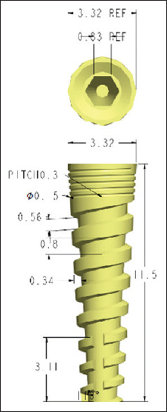
Implant model (3.3 mm × 11.5 mm)
Figure 7.
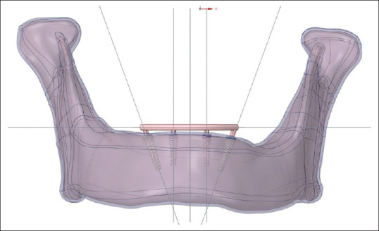
3D model with all-on-four concept. 3D – Three-dimensional
Figure 10.
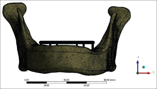
Meshing for model B (All on six)
Table 1.
Description of models
| Clinical situation | Implant number | Implant location | Implants positioning | Implant dimensions (mm) | References |
|---|---|---|---|---|---|
| All on 4 | 4 | 2-lateral incisor | Vertical | 3.3×11.5 | [2,17] |
| 2-second premolar | Inclined 17°to distal | 3.8×11.5 | [18] | ||
| All on 6 | 6 | 2-lateral incisor | Vertical | 3.3×11.5 | [9,19] |
| 2-second premolar | Vertical | 3.8×11.5 | |||
| 2-second molar | Vertical | 4.2×11.5 |
Figure 8.
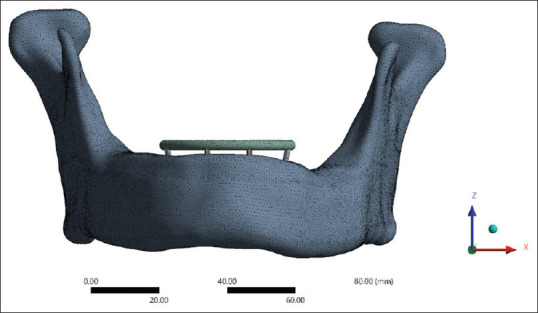
Meshing for model A (all on four)
Figure 9.
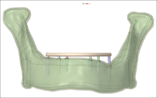
3D model with all-on-six concept. 3D – Three-dimensional
Finite element analysis
The 3D geometry was exported to FEA software ANSYS (ANSYS Inc, Canonsburg, Pa, USA) and was graphically simulated in the computer in the form of a mesh that defined its geometry. In a procedure known as discretization, the mesh was split into a number of linear tetrahedral components called elements that were connected at points called nodes. The precision of the computations depended on the size of the elements. The Models A and B were meshed with the following parameters: element size for cortical and trabecular bone: 0.5 mm element size for abutment, bar framework, and implant: 0.2 mm [Table 2].
Table 2.
Element and node numbers for Model A and B
| Model | Nodes | Elements |
|---|---|---|
| A (all on 4) | 1,039,145 | 605,946 |
| B (all on 6) | 2,182,276 | 1,384,964 |
All materials were considered to be isotropic, linearly elastic, and homogeneous. The mechanical properties of the materials used in this study are presented in Table 3. The configurations in this study were deliberately constrained in the mandible so as to simulate the boundary conditions most closely to the anatomical constraints. To simulate a fully osseointegrated state, bone–implant interface was deemed to be completely fixed, with no crestal bone loss around implants, and without any gap at the implant–abutment junction. A perfect fit was assumed between the implants, the bone, and the prosthetic structures. For evaluating and subsequent comparison of stress distribution on the bone–implant interface in each model, the following three loading conditions were evaluated[24] [Figure 11].
Table 3.
Mechanical properties of the materials used
Figure 11.
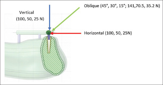
Loading conditions
Loading 1: Individual vertical load of 100 N was applied to all the implants
Loading 2: Individual horizontal load of 100 N was applied to all the implants
Loading 3: Individual oblique load at 45° buccolingually of 141 N was applied to all the implants.
The mathematical solutions were translated into visual outputs with varying degrees of color, ranging from red to blue, with red signifying the highest stress levels. The simulations’ findings were evaluated in terms of the maximum principal stress levels. Stress in a particular zone was analyses by UMAT Subroutine. The maximum stress values were obtained primarily for the purpose of comparing the two models and not for the purpose of reporting absolute values.
RESULTS
Tables 4 and 5 depict maximum principal stress (smax) experienced in cortical bone, trabecular bone, all implants, and left and right distal most implants. The maximum principal stress values (MPa) were more in Model A with respect to Model B for cortical bone, all implants, and the two distal most implants. However, the stress values for trabecular bone were in opposite trend under vertical and horizontal loading conditions.
Table 4.
Maximum principal stress on different components (MPa)
| Components | Model | Vertical load (100 N) | Horizontal load (100 N) | Oblique 45° load (141 N) |
|---|---|---|---|---|
| Cortical bone | Model A (4) | 77.56 | 16.11 | 139.85 |
| Model B (6) | 8.76 | 6.87 | 5.47 | |
| Trabecular bone | Model A (4) | 1.28 | 0.88 | 1.52 |
| Model B (6) | 2 | 1.94 | 0.96 | |
| All implants | Model A (4) | 438.85 | 52.21 | 244.43 |
| Model B (6) | 21.8 | 37.75 | 35.51 | |
| Left distal most implant | Model A (4) | 13.87 | 47.64 | 49.96 |
| Model B (6) | 21.08 | 23.66 | 22.25 | |
| Right distal most implant | Model A (4) | 18 | 49.39 | 244.33 |
| Model B (6) | 14.32 | 37.75 | 31.51 | |
| Left central (anterior) implant | Model A (4) | 438.85 | 41.13 | 25.08 |
| Model B (6) | 15.64 | 14.47 | 10.06 | |
| Right central (anterior) implant | Model A (4) | 15.79 | 52.21 | 29.29 |
| Model B (6) | 13.37 | 16.74 | 9.49 |
Table 5.
Maximum principal stress on different components (Mpa) (Representation on 3 D models)
| Component | Model | Vertical load (100 N) | Horizontal load (100 N) | Oblique 45° load (141 N) |
|---|---|---|---|---|
| Cortical bone | Model A (4) |

|

|

|
| Model B (6) |

|

|

|
|
| Trabecular bone | Model A (4) |

|

|

|
| Model B (6) |

|

|

|
|
| All implants | Model A (4) |

|

|

|
| Model B (6) |

|

|

|
|
| Left distal most implant | Model A (4) |

|

|

|
| Model B (6) |

|

|

|
|
| Right distal most implant | Model A (4) |

|

|

|
| Model B (6) |

|

|

|
|
| Left central (anterior) implant | Model A (4) |

|

|

|
| Model B (6) |

|

|

|
|
| Right central (anterior) implant | Model A (4) |

|

|

|
| Model B (6) |

|

|

|
When compared to the same implant in the “All-on-Four” model, the six-implant model showed less stress, with a notable drop in the most mesial implant. Also, it was observed that stress was concentrated in the same way in both models at the implant neck in all of the loading situations.
DISCUSSION
The manner in which stresses are distributed to the surrounding bone is a major element in deciding whether a dental implant prosthesis succeeds or fails.[25] Vertical and transverse loads from mastication result in stress gradients in the implant as well as on the bone.[26] These forces create deformations within the surrounding bone and induce strain in the implant and supporting tissue contact zone.[27] Hence, stress analysis become important to examine the biomechanical behavior of implant-based restorations and the surrounding tissues under functional forces. The present study compared biomechanical behaviors of two different treatment concepts of edentulism with full-mouth rehabilitation with dental implants (all-on-four-Model A and all-on-six-Model B). The clinical and radiographic versions of both these concepts are shown in Figures 12 and 13.
Figure 12.
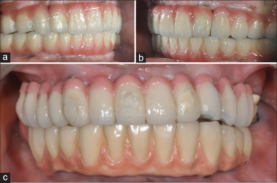
(a) Right lateral view, (b) Left lateral view, (c) Frontal view
Figure 13.
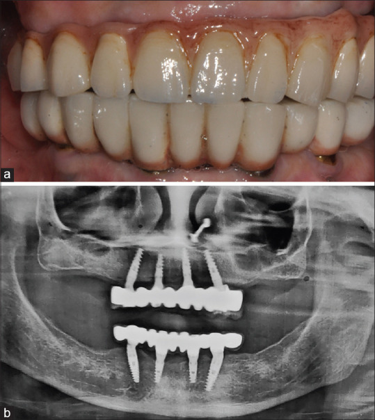
All-on-four (a) Frontal intra-oral view (b) Orthopantomogram
The ultimate oblique masticatory forces for several cylindrical implants were determined by Demenko et al.[28] They calculated the 118.2 N masticatory force by simulating it at a 75° angle to the occlusal plane. According to several researches, oblique forces better reflect occlusal stresses.[29,30] In our study, simulation of mastication was evaluated with the application of the vertical and horizontal loads (100 N) as well as a combined oblique load (141 N) at 45° inclination to the occlusal plane individually to each implant.[24] In all loading situations, irrespective of the model, the maximum principal stress was concentrated on the implant neck, as observed in other studies.[30,31,32,33] Model B (six implants) resulted in better overall stress distribution patterns. For this model, the stress was dispersed over a greater area, extending from implant #6 to implant #1 (cortical bone, trabecular bone, and implants). Presence of a distal support in this group (implant #6) led to a better stress distribution spanning a greater area. Further, all-on-six configuration showed lower maximum principal stress (smax) values on the cortical bone and implants when compared with Model A which consistently showed higher stress values in all the loading conditions.
However, considering the smax in the trabecular bone, Model B showed a higher value than the Model A in horizontal and vertical loading conditions. Previous research evaluating treatment techniques for the edentulous mandible have found similar results.[26] According to an in vivo study, the inclusion of additional implants leads to reduction in stress demonstrating a lower value in the axial loads in a six implant-supported prosthesis when compared to a prosthesis supported by four or three implants.[34] With a larger number of implants, Model B in our study was better able to transmit force to the implants and supporting tissues. Ozdemir Dogan et al. found that the six-implant model performed better than the four-implant type in the mandible.[10] However, they examined only the minimal principal stress on bone tissue while using a titanium framework. Almeida et al. observed lower maximum and minimum principal stress values with the six-implant model than with the four-implant model with a titanium framework.[19] In addition, their models have been simplified (i.e., there was no anatomical framework or implant threads). Silva et al. compared the biomechanical behavior of the “All-on-Four” system to that of a six-implant-supported maxillary prosthesis with slanted distal implants.[9] The scientists discovered that the two models’ stress locations and distribution patterns were similar. However, the addition of implants reduced the maximum von Mises stress values, but the presence of a cantilever increased the stress significantly. Overloading in cortical and trabecular bone occurs when the max exceeds 100–130 MPa and 5 MPa, respectively, according to physiological limits (ultimate bone strength).[35,36] The values found in both the treatment ideas were lower than those considered pathologic to bone tissue based on these parameters. The encouraging results of the six-implant concept suggested that in the cases of biomechanical risk (e.g., bruxism, low-quality bone), a larger number of implants may be required.[9] A further benefit is the elimination of a cantilever in this concept by using distal most implants. Rubo et al. and Bevilacqua et al. demonstrated that implants experience an increase in stress proportional to cantilever length.[37,38] This is a primary contributor to implant dentistry clinical failures.[36,39] Zampelis et al. in their two-dimensional study observed that when cantilever segments were removed, stress concentrations at the most coronal bone–implant contact site were subsequently lowered.[31] In our study, distal most implants experienced greater stress in the four-implant model than in the six-implant model. It was in agreement with a similar study done by Naini et al.[40] The authors fabricated 3-D finite element models of mandibular bone and four dental implants which were subsequently placed in two different configurations – with the distal most implants tilted (model A) or placed parallel (model S). They found that the posterior tilted implants experienced higher stresses in every loading scenario. Several investigations, however, have revealed that tilting the distal implants produces no significant difference in patterns of stress distribution, rather provides a biomechanical advantage by reducing cantilever segments.[31,41] Five to six implants were employed in the majority of clinical investigations evaluating tilted implants and demonstrated favorable outcomes.[42-44]
In FEA, the authenticity of the findings is largely dependent on the precise representation of the geometry of interest in the analyzed model. There are, however, some limitations to FEM, mainly in biologic simulations, that compel studies to assume simplifications.[44] Bone is an incredibly complicated living structure and its characteristics vary from individual to individual. In addition, the use of FEM when studying the extremely accurate anatomy of a bone structure may limit the analysis to that particular structure. As a result, a few simplifications were made to generalize the findings and make the study easier to conduct without jeopardizing the validity of the findings. The models in this study were assumed to be homogeneous and isotropic, ideal conditions were established, including 100% bone-to-implant contact and perfect fit of implants, abutments, and prosthetic bars. Since this study was comparative in nature, such assumptions would not interfere with the aims as they were present in both models. Furthermore, the screws at the implant–abutment and prosthesis–abutment interfaces were not modeled, and the connections were designed to be rigid. As finite element 3D models are simplified representations of the investigated structures, it is appropriate to interpret the numeric values reported in this study as biomechanical indications.
CONCLUSIONS
It could be inferred from the findings obtained in our study that the all-on-six treatment concept (Model B) which showed better biomechanical behavior could be considered a viable alternative for long-standing edentulous mandible rehabilitation. The additional number of implants in the six-implant model increased the prosthesis support and experienced reduced maximum principal stress with better distribution of stress over a larger region. The results of our study suggest that particularly in the cases of biomechanical risk (e.g., bruxism, low-quality bone), larger number of implants may be required for better stress distribution and in atrophic ridges, “All-on-Four” design could be a good alternative.
Financial support and sponsorship
Nil.
Conflicts of interest
There are no conflicts of interest.
REFERENCES
- 1.Klee de Vasconcellos D, Bottino MA, Saad PA, Faloppa F. A new device in immediately loaded implant treatment in the edentulous mandible. Int J Oral Maxillofac Implants. 2006;21:615–22. [PubMed] [Google Scholar]
- 2.Maló P, Rangert B, Nobre M. “All-on-Four”immediate-function concept with Brånemark system implants for completely edentulous mandibles: A retrospective clinical study. Clin Implant Dent Relat Res. 2003;5(Suppl 1):2–9. doi: 10.1111/j.1708-8208.2003.tb00010.x. [DOI] [PubMed] [Google Scholar]
- 3.Federick DR, Caputo AA. Effects of overdenture retention designs and implant orientations on load transfer characteristics. J Prosthet Dent. 1996;76:624–32. doi: 10.1016/s0022-3913(96)90441-2. [DOI] [PubMed] [Google Scholar]
- 4.Watanabe F, Hata Y, Komatsu S, Ramos TC, Fukuda H. Finite element analysis of the influence of implant inclination, loading position, and load direction on stress distribution. Odontology. 2003;91:31–6. doi: 10.1007/s10266-003-0029-7. [DOI] [PubMed] [Google Scholar]
- 5.Clelland NL, Gilat A. The effect of abutment angulation on stress transfer for an implant. J Prosthodont. 1992;1:24–8. doi: 10.1111/j.1532-849x.1992.tb00422.x. [DOI] [PubMed] [Google Scholar]
- 6.Clelland NL, Lee JK, Bimbenet OC, Brantley WA. A three-dimensional finite element stress analysis of angled abutments for an implant placed in the anterior maxilla. J Prosthodont. 1995;4:95–100. doi: 10.1111/j.1532-849x.1995.tb00323.x. [DOI] [PubMed] [Google Scholar]
- 7.Tuncelli B, Poyrazoglu E, Köylüoglu AM, Tezcan S. Comparison of load transfer by angulated, standard and inclined implant abutments. Eur J Prosthodont Restor Dent. 1997;5:85–8. [PubMed] [Google Scholar]
- 8.Bhering CL, Mesquita MF, Kemmoku DT, Noritomi PY, Consani RL, Barão VA. Comparison between all-on-four and all-on-six treatment concepts and framework material on stress distribution in atrophic maxilla: A prototyping guided 3D-FEA study. Mater Sci Eng C Mater Biol Appl. 2016;69:715–25. doi: 10.1016/j.msec.2016.07.059. [DOI] [PubMed] [Google Scholar]
- 9.Silva GC, Mendonça JA, Lopes LR, Landre J., Jr Stress patterns on implants in prostheses supported by four or six implants: A three-dimensional finite element analysis. Int J Oral Maxillofac Implants. 2010;25:239–46. [PubMed] [Google Scholar]
- 10.Özdemir Doğan D, Polat NT, Polat S, Şeker E, Gül EB. Evaluation of “all-on-four”concept and alternative designs with 3D finite element analysis method. Clin Implant Dent Relat Res. 2014;16:501–10. doi: 10.1111/cid.12024. [DOI] [PubMed] [Google Scholar]
- 11.De Oliveira BF, Seraidarian PI, de Oliveira SG, Landre J, Jr, Pithon MM, Oliveira DD. Tooth displacement in shortened dental arches: A three-dimensional finite element study. J Prosthet Dent. 2014;111:460–5. doi: 10.1016/j.prosdent.2013.07.022. [DOI] [PubMed] [Google Scholar]
- 12.Mazzoli A, Gracco A, Angela M, Giuseppe S. Use of MIMICS® software in three-dimensional cephalometric evaluation of soft tissues of the face. Comput Methods Biomech Biomed Eng Imaging Vis. 2017;5:15–3. [Google Scholar]
- 13.Xi T, Schreurs R, Heerink WJ, Bergé SJ, Maal TJ. A novel region-growing based semi-automatic segmentation protocol for three-dimensional condylar reconstruction using cone beam computed tomography (CBCT) PLoS One. 2014;9:e111126. doi: 10.1371/journal.pone.0111126. [DOI] [PMC free article] [PubMed] [Google Scholar]
- 14.Zhu H, Gao S, Li M, Pan W. Adaptive tetrahedral remeshing for modified solid models. Graph Models. 2012;74:76–86. [Google Scholar]
- 15.Calì M, Oliveri SM, Calì P, Ambu R. A NURBS-based solid modeling to enhance rapid prototyping in the restoration of decorative elements. Int J Interact Des Manuf. 2021;15:129–32. [Google Scholar]
- 16.Sugiura T, Yamamoto K, Horita S, Murakami K, Tsutsumi S, Kirita T. The effects of bone density and crestal cortical bone thickness on micromotion and peri-implant bone strain distribution in an immediately loaded implant: A nonlinear finite element analysis. J Periodontal Implant Sci. 2016;46:152–65. doi: 10.5051/jpis.2016.46.3.152. [DOI] [PMC free article] [PubMed] [Google Scholar]
- 17.Sannino G. All-on-4 concept: A 3-dimensional finite element analysis. J Oral Implantol. 2015;41:163–71. doi: 10.1563/AAID-JOI-D-12-00312. [DOI] [PubMed] [Google Scholar]
- 18.Fazi G, Tellini S, Vangi D, Branchi R. Three-dimensional finite element analysis of different implant configurations for a mandibular fixed prosthesis. Int J Oral Maxillofac Implants. 2011;26:752–9. [PubMed] [Google Scholar]
- 19.Almeida EO, Rocha EP, Júnior AC, Anchieta RB, Poveda R, Gupta N, et al. FEA Using implant and atrophic maxilla. Clin Implant Dent Relat Res. 2015;17:332–342. doi: 10.1111/cid.12129. [DOI] [PubMed] [Google Scholar]
- 20.AZO Materials. Grade 23 Ti 6Al 4V ELI Alloy (UNS R56401) [Last accessed on 2021 Dec 01;Last updated on 2013 Jul 30]. Available from:https://www.azom.com/article.aspx?ArticleID=9365 .
- 21.Sertgöz A. Finite element analysis study of the effect of superstructure material on stress distribution in an implant-supported fixed prosthesis. Int J Prosthodont. 1997;10:19–27. [PubMed] [Google Scholar]
- 22.Sevimay M, Turhan F, Kiliçarslan MA, Eskitascioglu G. Three-dimensional finite element analysis of the effect of different bone quality on stress distribution in an implant-supported crown. J Prosthet Dent. 2005;93:227–34. doi: 10.1016/j.prosdent.2004.12.019. [DOI] [PubMed] [Google Scholar]
- 23.Bacchi A, Consani RL, Mesquita MF, Dos Santos MB. Effect of framework material and vertical misfit on stress distribution in implant-supported partial prosthesis under load application: 3-D finite element analysis. Acta Odontol Scand. 2013;71:1243–9. doi: 10.3109/00016357.2012.757644. [DOI] [PubMed] [Google Scholar]
- 24.Geng JP, Xu DW, Tan KB, Liu GR. Finite element analysis of an osseointegrated stepped screw dental implant. J Oral Implantol. 2004;30:223–33. doi: 10.1563/0654.1. [DOI] [PubMed] [Google Scholar]
- 25.Van Oosterwyck H, Duyck J, Vander Sloten J, Van der Perre G, De Cooman M, Lievens S, et al. The influence of bone mechanical properties and implant fixation upon bone loading around oral implants. Clin Oral Implants Res. 1998;9:407–18. doi: 10.1034/j.1600-0501.1996.090606.x. [DOI] [PubMed] [Google Scholar]
- 26.Barbier L, Vander Sloten J, Krzesinski G, Schepers E, Van der Perre G. Finite element analysis of non-axial versus axial loading of oral implants in the mandible of the dog. J Oral Rehabil. 1998;25:847–58. doi: 10.1046/j.1365-2842.1998.00318.x. [DOI] [PubMed] [Google Scholar]
- 27.Bidez MW, Misch CE. Force transfer in implant dentistry: Basic concepts and principles. J Oral Implantol. 1992;18:264–74. [PubMed] [Google Scholar]
- 28.Demenko V, Linetskiy I, Nesvit K, Shevchenko A. Ultimate masticatory force as a criterion in implant selection. J Dent Res. 2011;90:1211–5. doi: 10.1177/0022034511417442. [DOI] [PubMed] [Google Scholar]
- 29.Holmgren EP, Seckinger RJ, Kilgren LM, Mante F. Evaluating parameters of osseointegrated dental implants using finite element analysis –A two-dimensional comparative study examining the effects of implant diameter, implant shape, and load direction. J Oral Implantol. 1998;24:80–8. doi: 10.1563/1548-1336(1998)024<0080:EPOODI>2.3.CO;2. [DOI] [PubMed] [Google Scholar]
- 30.Ladd AJ, Kinney JH. Numerical errors and uncertainties in finite-element modeling of trabecular bone. J Biomech. 1998;31:941–5. doi: 10.1016/s0021-9290(98)00108-0. [DOI] [PubMed] [Google Scholar]
- 31.Zampelis A, Rangert B, Heijl L. Tilting of splinted implants for improved prosthodontic support: A two-dimensional finite element analysis. J Prosthet Dent. 2007;97:S35–43. doi: 10.1016/S0022-3913(07)60006-7. [DOI] [PubMed] [Google Scholar]
- 32.Sertgöz A, Güvener S. Finite element analysis of the effect of cantilever and implant length on stress distribution in an implant-supported fixed prosthesis. J Prosthet Dent. 1996;76:165–9. doi: 10.1016/s0022-3913(96)90301-7. [DOI] [PubMed] [Google Scholar]
- 33.Bellini CM, Romeo D, Galbusera F, Agliardi E, Pietrabissa R, Zampelis A, et al. Afinite element analysis of tilted versus nontilted implant configurations in the edentulous maxilla. Int J Prosthodont. 2009;22:155–7. [PubMed] [Google Scholar]
- 34.Duyck J, Van Oosterwyck H, Vander Sloten J, De Cooman M, Puers R, Naert I. Magnitude and distribution of occlusal forces on oral implants supporting fixed prostheses:An in vivo study. Clin Oral Implants Res. 2000;11:465–75. doi: 10.1034/j.1600-0501.2000.011005465.x. [DOI] [PubMed] [Google Scholar]
- 35.Reilly DT, Burstein AH. The elastic and ultimate properties of compact bone tissue. J Biomech. 1975;8:393–405. doi: 10.1016/0021-9290(75)90075-5. [DOI] [PubMed] [Google Scholar]
- 36.Baggi L, Pastore S, Di Girolamo M, Vairo G. Implant-bone load transfer mechanisms in complete-arch prostheses supported by four implants: A three-dimensional finite element approach. J Prosthet Dent. 2013;109:9–21. doi: 10.1016/S0022-3913(13)60004-9. [DOI] [PubMed] [Google Scholar]
- 37.Bevilacqua M, Tealdo T, Menini M, Pera F, Mossolov A, Drago C, et al. The influence of cantilever length and implant inclination on stress distribution in maxillary implant-supported fixed dentures. J Prosthet Dent. 2011;105:5–13. doi: 10.1016/S0022-3913(10)60182-5. [DOI] [PubMed] [Google Scholar]
- 38.Rubo JH, Capello Souza EA. Finite-element analysis of stress on dental implant prosthesis. Clin Implant Dent Relat Res. 2010;12:105–13. doi: 10.1111/j.1708-8208.2008.00142.x. [DOI] [PubMed] [Google Scholar]
- 39.Malhotra AO, Padmanabhan TV, Mohamed K, Natarajan S, Elavia U. Load transfer in tilted implants with varying cantilever lengths in an all-on-four situation. Aust Dent J. 2012;57:440–5. doi: 10.1111/adj.12002. [DOI] [PubMed] [Google Scholar]
- 40.Naini RB, Nokar S, Borghei H, Alikhasi M. Tilted or parallel implant placement in the completely edentulous mandible?A three-dimensional finite element analysis. Int J Oral Maxillofac Implants. 2011;26:776–81. [PubMed] [Google Scholar]
- 41.Krekmanov L, Kahn M, Rangert B, Lindström H. Tilting of posterior mandibular and maxillary implants for improved prosthesis support. Int J Oral Maxillofac Implants. 2000;15:405–14. [PubMed] [Google Scholar]
- 42.Capelli M, Zuffetti F, Del Fabbro M, Testori T. Immediate rehabilitation of the completely edentulous jaw with fixed prostheses supported by either upright or tilted implants: A multicenter clinical study. Int J Oral Maxillofac Implants. 2007;22:639–44. [PubMed] [Google Scholar]
- 43.Testori T, Del Fabbro M, Capelli M, Zuffetti F, Francetti L, Weinstein RL. Immediate occlusal loading and tilted implants for the rehabilitation of the atrophic edentulous maxilla: 1-year interim results of a multicenter prospective study. Clin Oral Implants Res. 2008;19:227–32. doi: 10.1111/j.1600-0501.2007.01472.x. [DOI] [PubMed] [Google Scholar]
- 44.Geng JP, Tan KB, Liu GR. Application of finite element analysis in implant dentistry: A review of the literature. J Prosthet Dent. 2001;85:585–98. doi: 10.1067/mpr.2001.115251. [DOI] [PubMed] [Google Scholar]


