

Summary
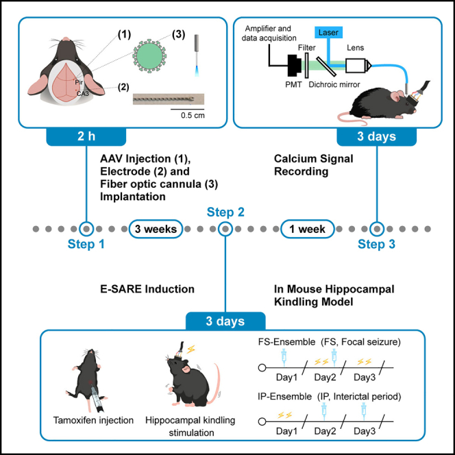
Epileptic networks are characterized by two states, seizures or more prolonged interictal periods. Here, we present the procedure for labeling seizure-activated and interictal-activated neuronal ensembles in mouse hippocampal kindling model using an enhanced-synaptic-activity-responsive element. We describe the seizure model establishment, tamoxifen induction, electrical stimulation, and calcium signal recording of labeled ensembles. This protocol has demonstrated dissociated calcium activities in the two ensembles during focal seizure dynamics and can be applied to other animal models of epilepsy.
For complete details on the use and execution of this protocol, please refer to Lai et al. (2022).1
Subject area(s): Behavior, Neuroscience
Graphical abstract
Highlights
-
•
Stereotactic surgery for electrical stimulation in mouse hippocampal kindling model
-
•
Expression of GCaMP in seizure-dependent neurons of the piriform cortex
-
•
Calcium activity recording during focal seizure dynamics
Publisher’s note: Undertaking any experimental protocol requires adherence to local institutional guidelines for laboratory safety and ethics.
Epileptic networks are characterized by two states, seizures or more prolonged interictal periods. Here, we present the procedure for labeling seizure-activated and interictal-activated neuronal ensembles in mouse hippocampal kindling model using an enhanced-synaptic-activity-responsive element. We describe the seizure model establishment, tamoxifen induction, electrical stimulation, and calcium signal recording of labeled ensembles. This protocol has demonstrated dissociated calcium activities in the two ensembles during focal seizure dynamics and can be applied to other animal models of epilepsy.
Before you begin
Epilepsy is a neurologic condition characterized by repeated transient seizures separated by longer interictal periods.2 Seizures are caused by abnormally synchronous neuronal activity in one or more regions of the brain.3 The period between one seizure and the next is often referred to as the interictal period.4 Previous studies have indicated that interictal and ictal activities may be generated by distinct neuronal populations and distinct network mechanisms, however, it is not clear how seizures and interictal periods translate into each other and how they affect each other.5,6 To address this important question in the field of epilepsy and to identify future therapeutic targets, we focus on studying the function of epileptic status-related neuronal ensembles.1
In this article, by employing mouse hippocampal kindling procedures, we demonstrate a detailed step-by-step method that uses an enhanced synaptic activity-responsive element (E-SARE) in combination with genetically encoded effectors to characterize and manipulate neuronal populations that are recruited in focal seizures and interictal activity in the piriform cortex, a region that plays a key role in the generation and propagation of epileptic seizures. In addition, we describe methods for in vivo calcium signal recording to investigate the involvement of these two ensembles in focal seizures.
Notably, besides being suitable for the mouse hippocampal kindling model, it can even be applied to other animal models of epilepsy for the investigation of the relationship between ictal and interictal activities in epilepsy.
Institutional permissions
All experimental procedures were performed in accordance with the Zhejiang University Animal Experimentation Committee.
Preparation of materials for AAV injection, electrode and fiber optic cannula implantation
Timing: 6 h
-
1.Preparation of AAV.
-
a.AAV2/9-ESARE-ERT2CreERT2-PEST (viral titers: 6.94 × 10¹² v.g./mL) and AAV2/9-EF1a-DIO-GCaMP6s (viral titers: 1.51 × 10¹³ v.g./mL) can be bought from Taitool Bioscience (Shanghai), which are also accessible from UNC Vector Core.
-
b.Thaw the virus stock solution on ice and take an aliquot, mix the two viruses and PBS diluent in the ratio of 1:1:1, and store at −80°C.
-
a.
Note: Mixed viruses are recommended to be stored for no more than six months and the volume of the aliquot can be flexibly adjusted according to the daily dosage (0.3 μL per mouse) so that individual aliquots can be used up within one day to avoid repeated freezing and thawing.
Alternatives: The PBS diluent here is provided by the virus company. If the purchased virus does not come with PBS, Milli-Q water can be used instead.
-
2.Preparation of glass micropipette.
-
a.The glass micropipette used for AAV injection is borosilicate glass with an outer diameter of 1.5 mm and an inner diameter of 0.86 mm (Sutter Instrument, USA).
-
b.Use the PC-10 micropipette vertical puller (Narishige, Japan) to pull the glass micropipette (tip diameter 15–20 μm) for AAV injection.
-
a.
Note: The length of the micropipette depends on the depth of injection, which in this study is at least 6 mm.
-
3.Preparation of microliter syringe equipped with glass micropipette (Figure 1).
-
a.Aspirate liquid paraffin oil with a 1 μL syringe, and fill the glass micropipette with liquid paraffin oil as well.
-
b.Connect the glass micropipette to the syringe while avoiding any air bubbles.
-
c.Wipe off the paraffin oil at the junction site, apply the hot melt glue at the junction site, and leave it for 1–2 min to make it solid.
-
d.Check the airtightness of the injection system.
-
i.Push the plunger of the 1 μL syringe until the paraffin oil overflows from the glass micropipette tip.
-
ii.Check that there is no excess paraffin oil overflowing from the junction site between the glass micropipette and the syringe.
-
i.
-
e.Attach the syringe with glass micropipette to the holder of the stereotaxic apparatus (68507, RWD Life Science, China).
-
a.
CRITICAL: Make sure that no paraffin oil spills out from the junction site before applying the hot melt glue, otherwise this may cause problems with the air tightness of the AAV injection.
-
4.Preparation of electrode (Figure 2).
-
a.The hand-made electrode is made of Teflon-coated stainless-steel wire (791500, DA 0.127 mm, A.M. System, USA).
-
b.Twist it into a double-stranded spiral at a certain density.
-
i.Fold a single Teflon-coated stainless-steel wire with a length of 20 cm in half and clamp the ends with hemostatic forceps.
-
ii.Secure one hemostatic forceps with a magnet and twist the other hemostatic forceps 100 turns.
-
i.
-
c.Split one end of the double-stranded spiral electrode into a u-shape (the maximal tip separation is 0.5–0.6 mm) and peel off 0.5 mm of insulation at the tip of the electrode with a surgical blade to allow for electrical stimulation.
-
a.
-
5.Preparation of female connector (Figure 3).
-
a.Bend the double-row female header with a plier and cut it so that each piece has three pairs of electrode pins.
-
b.Tilt each electrode pin outward by approximately 45° and make the two adjacent electrode pins on the same side contact each other and become the same channel.Note: The purpose of doing so is to increase the size of the female connector for easy handling, or you can use a female connector with two pairs of electrode pins.
-
c.Apply silicone sealant to the bottom of the electrode pins and leave it to harden.CRITICAL: Make sure the silicone sealant completely covers the bottom to avoid penetration of the dental cement into the holes of the female connector.
-
a.
Figure 1.

Syringe equipped with glass micropipette
A 1 μL syringe filled with paraffin oil is connected with a glass micropipette filled with paraffin oil via the hot melt glue and mounted on a syringe pump holder.
Figure 2.

Hand-made double-stranded spiral electrode
An electrode made of stainless-steel wire coated with Teflon, twisted into a double-stranded spiral with the tip divided into a u-shape and peeled off its insulating layer.
Figure 3.

Process of making a female connector
A female connector is made from the double-row female header according to the following steps: (1) cut to each piece with three pairs of electrode pins; (2) tilt each electrode pin outward; (3) make the two adjacent electrode pins on the same side contact each other; (4) apply silicone sealant to the bottom of the electrode pins.
Set up for AAV injection and surgery
-
6.
Gather supplies for AAV injection, electrode and fiber optic cannula implantation surgery (Figure 4).
-
7.Prepare experimental animals.
-
a.Use healthy C57BL/6J (male, 2–4 months, 20–30 g).
-
a.
Figure 4.

Surgical supplies
Supplies required for AAV injection, electrode and fiber optic cannula implantation surgery.
Key resources table
| REAGENT or RESOURCE | SOURCE | IDENTIFIER |
|---|---|---|
| Bacterial and virus strains | ||
| AAV2/9-ESARE-ERT2CreERT2-PEST | Taitool Bioscience (Shanghai) | N/A |
| AAV2/9-EF1a-DIO-GCaMP6s | Taitool Bioscience (Shanghai) | N/A |
| Chemicals, peptides, and recombinant proteins | ||
| Corn oil | Shandong Samsung Maize Industry Technology Co., Ltd. | N/A |
| Ethylene glycerol | Sinopharm Chemical | 107-21-1 |
| Glycerol | Sinopharm Chemical | 56-81-5 |
| 30% Hydrogen peroxide | Sinopharm Chemical | 7722-84-1 |
| Iodophor | Zhongjia Disinfection Technology Co., Ltd. | N/A |
| Paraffin oil | Sinopharm Chemical | 8012-95-1 |
| Paraformaldehyde | Macklin | 30525-89-4 |
| PBS powder | Biosharp | BL601A |
| Sodium pentobarbital | Sigma-Aldrich | 57-33-0 |
| Sucrose | Sinopharm Chemical | 57-50-1 |
| Tamoxifen | Sigma-Aldrich | Cat# T5648 |
| Experimental models: Organisms/strains | ||
| Mouse: C57BL/6 (Wild type, male, 8–10 weeks) | The Jackson Laboratory | RRID:IMSR_JAX:000664 |
| Software and algorithms | ||
| LabChart | ADInstruments | https://www.adinstruments.com/support/software |
| PowerLab | ADInstruments | https://www.adinstruments.com.cn/products/PowerLab |
| MATLAB | MathWorks | https://www.mathworks.com/products/matlab/ |
| Other | ||
| Aluminum foil | Heavy Duty | N/A |
| Anti-fluorescence quencher | Yeasen Biotech | 36308ES20 |
| Constant-current stimulator | Nihon Kohden | SEN-7203, SS-202J |
| Dental cement | Feiying (Anyang) | N/A |
| Double-row female header (1.27∗3.4 mm) | Shenzhen Unicable Connector Co., Ltd. | N/A |
| Fiber optic cannula | Inper Co., Ltd. | N/A |
| Freezing microtome | Thermo Fisher Scientific | CryoStar NX70 |
| Glass micropipette | Sutter instrument | B100-58-10 |
| Hemostatic forceps | Jinzhong Surgical Instrument | J31120 |
| Laser confocal microscope | Leica | TCS SP8 |
| Microinjection pump | World Precision Instruments | Micro 4 |
| Microliter syringe (1 μL) | Shanghai Gaoge Industry and Trading Co., Ltd. | N/A |
| Needle (25G) | Shanghai Kindly Medical Instruments Co., Ltd. | N/A |
| Ophthalmic forceps | Vetus Tools Co., Ltd. | ST-15 |
| Scissor | Jinzhong Surgical Instrument | Y00030 |
| Silicone sealant | Kafuter | K-704N |
| Single-channel fiber photometry | Thinker Tech Nanjing Biotech Co., Ltd. | N/A |
| Skull drill | RWD Life Science | 78001 |
| Skull screw | Lin’an Mingxiang Precision Components Factory | Customized (M 0.8-OD 1.7 mm-L 2 mm) |
| Solder | Zhejiang QLG Holdings Co., Ltd. | N/A |
| Soldering station | Quick Safe | QUICK936A |
| Stereotaxic apparatus with accessories | RWD Life Science | 68507 |
| Surgical blade | Jinzhong Surgical Instrument | JOB020 |
| Teflon-coated stainless-steel wire | A.M. System | 791500 |
| Tweezers | Jinzhong Surgical Instrument | JD1060 |
Materials and equipment
0.01 M PBS buffer
| Reagent | Final concentration | Amount |
|---|---|---|
| PBS, powder | 0.01 M | 1 bag |
| ddH2O | N/A | to 2 L |
| Total | N/A | 2 L |
Keep at 25°C for up to 1 month.
4% PBS-buffered PFA
| Reagent | Final concentration | Amount |
|---|---|---|
| Paraformaldehyde | 4% | 40 g |
| 0.01 M PBS buffer | N/A | to 1 L |
| Total | N/A | 1 L |
Keep at 4°C for up to 1 month.
30% sucrose solution
| Reagent | Final concentration | Amount |
|---|---|---|
| Sucrose | 30% | 30 g |
| 0.01 M PBS buffer | N/A | to 100 mL |
| Total | N/A | 100 mL |
Keep at 4°C for up to 2 weeks.
Step-by-step method details
AAV injection, electrode and fiber optic cannula implantation
This step describes the entire surgical procedure required for performing E-SARE induction experiments and calcium signal recording in mouse hippocampal kindling model, including AAV injection, electrode and fiber optic cannula implantation.
-
1.Animal anesthesia and mounting (Figure 5A).
-
a.Anesthetize a 2-month-old C57 wild-type male mouse with sodium pentobarbital (50 mg/kg, i.p.), then mount it in a stereotaxic apparatus (68507, RWD Life Science, China).
-
b.Remove hair from the mouse’s head, disinfect with iodophor, then cut the skin of the mouse’s head and wipe it with sterile cotton dipped in a small amount of 3% hydrogen peroxide to expose the skull suture.
-
c.Adjust the height of the nasal clip to ensure the bregma and lambda are at the same vertical level (error not more than 0.1 mm).
-
a.
Note: To reduce hypothermia, do surgery on a heating pad or under a heat lamp.
-
2.AAV injection (Figure 5B). troubleshooting 5.
-
a.Prepare a viral cocktail containing AAV-ESARE-ERT2CreERT2-PEST and AAV-EF1a-DIO-GCaMP6s at 0.3 μL per mouse.
-
b.Load the AAV solution into the glass micropipette.
-
c.Determine the coordinate of the piriform cortex (AP: +0.5 mm, ML: -2.8 mm, DV: -5.4 mm) for the AAV injection site and drill a hole (0.8 mm diameter) with a skull drill.
-
d.Move the glass micropipette to the injection site and lower the micropipette to a depth of 5.4 mm slowly.
-
e.Inject the cocktail virus (0.3 μL) at a rate of 50 nL/min, leave the glass micropipette in place for 10 min after injection, and then slowly withdraw it.
-
a.
-
3.Electrode implantation (Figures 5C–5H).
-
a.Determine the coordinate of the CA3 (AP: -2.9 mm, ML: -3.0 mm, DV: -3.2 mm) for the electrode site and drill a hole (0.8 mm diameter) with a skull drill.
-
b.Drill 4 more holes (0.5 mm diameter) at the anterior bregma, posterior lambda, and the left and right sides of the skull suture separately with a skull drill.
-
c.Screw in skull screws in each hole for dental cement fixation. troubleshooting 1.Note: If the dura is still apparent after drilling, it can be removed gently with ophthalmic forceps.CRITICAL: Drill slowly by applying only gentle pressure to the skull to avoid causing trauma to the brain. The sound of the drill will increase in pitch as the drill advances through the skull. You may also see a small amount of fluid leak. Stop immediately.CRITICAL: The holes for screwing should not be drilled very large (0.5 mm diameter is recommended), otherwise the screw will easily slip into the holes and thus cling to the skull surface, rendering the dental cement fixation ineffective. A proper hole will allow the screw to be screwed in tightly, and the screw should be screwed in at a depth that leaves a gap with the skull surface.
-
d.Wrap copper wire around the anterior bregma screw and posterior lambda screw for cortical EEG recording and grounding reference, respectively.
-
e.Slowly insert the electrode into the pre-drilled hole.CRITICAL: Note the orientation of the downward-facing u-shaped tip when implanting the electrode to fit the structure of the implanted nucleus. For example, in this study,1 the electrode was implanted in the hippocampus, which is long and narrow from the rostrum to the cauda, so the two ends of the u-shaped tip should be placed anteriorly and posteriorly.
-
f.Fix the electrode and screw with a small amount of dental cement (∼2 mm thick layer for core fixation).
 Pause Point: Wait for 10–20 min for the dental cement to be solidified before removing the holder from the electrode.
 -
g.Bend the exposed part of the electrode near the cement by 90 degrees and fix it again with a small amount of dental cement.Pause Point: Wait for 10–20 min for the dental cement to be solidified.CRITICAL: Bend the fixed electrode 90 degrees and fix it again with dental cement to make it more stable, otherwise, the unwinding action may cause the electrode to wobble in the brain and damage the brain tissue.
-
a.
-
4.Fiber optic cannula implantation (Figure 5I).
-
a.Prepare a fiber optic cannula with a diameter of 200 μm, a length of 6 mm, and a numerical aperture of 0.5. Clean the exposed part of the optical fiber with 75% alcohol and then remove the residual alcohol with sterile PBS.
-
b.Insert the fiber optic cannula into the AAV injection site, and the implantation depth should be 0.2 mm shallower than the AAV injection depth.
-
c.Apply the dental cement (2 mm thick layer) to cover the fiber optic cannula and the adjacent screw.
-
a.
Note: The optimal distance between the AAV injection site and the fiber optic cannula is determined by factors such as the desired activation volume of the targeted brain region, wavelength, power density, and opsin sensitivity.7 In practice, we empirically place the fiber optic cannula 0.2 mm dorsal to the AAV injection site.
-
5.Female connector welding (Figures 5J–5L). troubleshooting 2.
-
a.Unwind the double-stranded spiral electrode with tweezers.
-
b.Strip the insulation from the tip of the wires (∼1cm) with tweezers, hold the female header with one hand, and connect the wires to the electrode pins of the female connector with a solder gun held in the other hand. troubleshooting 3.
-
c.Connect the copper wire at the anterior and posterior screws to the female connector with a solder gun.
-
d.Apply dental cement at the skull openings with electrode wires and the space between the skull and the bottom side of the female connector.
-
a.
Note: Make sure that all of the wires and wire connections on the connector pins are embedded into the cement (∼5 mm thick layer).
-
6.Provide post-operative care.
-
a.Do not leave until the mouse is ambulatory.
-
b.Keep on the heating pad and/or wrapped up for warmth.
-
c.Give analgesia (e.g., meloxicam) for at least 24 h.
-
d.Supplement food and water as necessary.
-
e.House mice on soft bedding and make sure they can move freely without their headcaps and implants hitting obstacles.
-
a.
Figure 5.

The main experimental steps of AAV injection, electrode and fiber optic cannula implantation
(A) Fix the head of the mouse in the stereotaxic apparatus.
(B) Determine the coordinate of the piriform cortex (AP: +0.5 mm, ML: -2.8 mm, DV: -5.4 mm) for the AAV injection site and drill a hole with a skull drill.
(C) Determine the coordinate of the CA3 (AP: -2.9 mm, ML: -3.0 mm, DV: -3.2 mm) for the electrode site and drill a hole with a skull drill; then drill 4 more holes at the anterior bregma, posterior lambda, and the left and right sides of the skull suture separately with a skull drill; finally, screw in skull screws in each hole for dental cement fixation.
(D) Wrap copper wire around the anterior bregma screw and posterior lambda screw for cortical EEG recording and grounding reference, respectively.
(E) Slowly insert the electrode into the pre-drilled hole.
(F) Fix the electrode and screw it with a small amount of dental cement (core fixation).
(G) Bend the exposed part of the electrode near the cement by 90 degrees.
(H) Fix the bend with a small amount of dental cement.
(I) Insert the fiber optic cannula into the AAV injection site, and the implantation depth should be 0.2 mm shallower than the AAV injection depth.
(J) Unwind the double-stranded spiral electrode and strip the insulation from the tip of the wires (∼1cm).
(K) Connect the electrode and the copper wire at the anterior and posterior screws to electrode pins of the female connector with solder.
(L) Apply dental cement at the skull openings with electrode wires and the space between the skull and the bottom side of the female connector.
E-SARE induction experiments in mouse hippocampal fast kindling model
Following the completion of the AAV injection, electrode and fiber optic cannula implantation, wait three weeks for virus transformation, and then label activity-dependent neuronal ensembles in mouse hippocampal kindling model under tamoxifen induction.
-
7.Prepare tamoxifen solution. troubleshooting 5.
-
a.Calculate the tamoxifen dose based on the mice’s body weight (80 mg/kg).
-
b.Prepare the tamoxifen solution (20 mg/mL) by adding the tamoxifen crystals directly to corn oil in a tube shielded from light with aluminum foil.CRITICAL: Tamoxifen needs to be handled carefully because of its toxicity.
-
c.Immerse the tube containing the tamoxifen solution in an ultrasonic water bath at 37°C for 30 min until the tamoxifen is completely dissolved (the solution should be clear with no visible crystals). troubleshooting 4.Alternatives: Place the tube containing the tamoxifen solution horizontally on a shaker at 25°C and shake for 24 h to make it dissolve.
-
d.Store at 4°C for use.Note: Tamoxifen is quite light-sensitive and therefore needs to be protected from light during preparation and storage.Note: The tamoxifen solution should be clear; if the solution becomes cloudy, it should be discarded. Tamoxifen solution can be stored at 4°C for up to four weeks, but we recommend preparing the tamoxifen solution fresh, just prior to use.
-
a.
-
8.
Tamoxifen induction in hippocampal kindling model. troubleshooting 5.
IP-Ens (neuronal ensemble activated in the interictal period) labeling:-
a.Give electrical stimulation of the hippocampus (400 μA, 20 Hz, 2 s trains, 1 ms monophasic square-wave pulses, 30 min apart, 2 times)8,9,10 with a constant-current stimulator (SEN-7203, SS-202J; Nihon Kohden, Japan) to induce 2 focal seizures on the first day (9:00 a.m.).Note: The after-discharge durations (ADDs) induced by these two hippocampal kindling stimulations are typically 10–20 s.
-
b.Intraperitoneally inject (80 mg/kg) tamoxifen solution (20 mg/mL) at the same time (9:00 a.m.) on the second and third days.Note: Because of the high viscosity of corn oil, both aspirating and injecting tamoxifen solution need to be done slowly.CRITICAL: Ensure that tamoxifen is administered at the same time, thus labeling interictal-activated ensemble within the same time interval. (Because it is unclear whether the neuronal ensembles activated during the interictal period in different time intervals have distinct functions).Pause Point: Wait 1 week for viral expression before performing calcium signal recording.
FS-Ens (neuronal ensemble activated in electrical-induced focal seizures) labeling:-
c.Intraperitoneally inject (80 mg/kg) tamoxifen solution (20 mg/mL) on the first day (9:00 a.m.).
-
d.Give electrical stimulation of the hippocampus (400 μA, 20 Hz, 2 s trains, 1 ms monophasic square-wave pulses, 30 min apart, 2 times) with a constant-current stimulator (SEN-7203, SS-202J; Nihon Kohden, Japan) to induce 2 focal seizures on the second day (9:00 a.m.).
-
e.Repeat operations a and b above for two consecutive days.Note: The time between the administration of tamoxifen and the application of electrical stimulation is 24 h apart.11CRITICAL: Avoid additional environmental or operational stimulations during tamoxifen induction experiments. For example, before tamoxifen injection, acclimate mice to the stimuli associated with intraperitoneal injection, including grasping and injecting empty needle; when injecting tamoxifen, take care to gently grasp mice as well as gently inject; after tamoxifen injection, keep mice in their previously familiar environment for at least three days, e.g., without changing bedding as well as co-caging mice.Pause Point: Wait 1 week for viral expression before performing calcium signal recording.
-
a.
Calcium signal recording of labeled viruses
This step describes the composition and setup of the fiber photometry system, the recording of EEG and calcium fluorescence signals, and the analysis of the photometry data.
-
9.Fiber photometry system settings.
-
a.Use the single-channel fiber photometry system (Thinker Tech Nanjing Biotech Co., Ltd.) for calcium fluorescence recordings, consisting of a 488 nm diode laser (OBIS 488LS; Coherent) (light intensity 0.01–0.03 mW), reflected by a dichroic mirror (MD498, Thorlabs), and coupled by an objective lens to an optic fiber (fiber diameter 200 μm, 0.37 NA, Inper Co., Ltd., China).
-
b.Turn on the optic fiber recording instrument and the software.
-
a.
-
10.EEG and calcium fluorescence signal recordings.
-
a.Select the storage location for the record file, and click record to start.
-
b.Record the EEGs with PowerLab system (ADInstruments, Australia) at a sample rate of 1000 Hz (Notch filter: 50 Hz) and calcium fluorescence signals in the basal state for 100 s.
-
c.Apply 2 s of electrical stimulation to induce a seizure and observe the animal behavior to determine the seizure stage which is scored by a trained observer according to the Racine scale,12 while recording the EEGs and calcium fluorescence signals for another 100 s.
-
a.
Note: Racine scale: (1) facial movements such as chewing, orofacial twitching, and sluggishness; (2) head nodding; (3) unilateral forelimb clonus; (4) bilateral forelimb clonus and rearing; (5) bilateral forelimb clonus, rearing, and falling. Stages 1–3 are considered focal seizures and stages 4–5 are generalized seizures.13
-
11.Photometry data analysis.
-
a.Export the photometry data to MATLAB Mat files using the MATLAB plug-in called OpSignal provided by Thinker Tech (Thinker Tech Nanjing Biotech Co., Ltd.).
-
b.Take the average fluorescence value 2 s before the zero point as the control baseline fluorescence intensity (defined as F0).
-
c.Calculate the difference between the current fluorescent intensity F and the baseline fluorescence intensity F0.
-
d.Use the ratio, that is ΔF/F=(F-F0)/F0, to analyze the calcium signal change for each event.
-
a.
-
12.Verification of virus expression, electrode and fiber optic cannula site.
-
a.Anesthetize mice by intraperitoneal injection of sodium pentobarbital (100 mg/kg).CRITICAL: Confirm that mice are fully anesthetized (e.g., check for the lack of whisker movement) before proceeding to the next step.
-
b.Lay the mouse on its back.
-
i.Open the mouse chest to expose the heart.
-
ii.Insert the left ventricle with a needle (25G) for perfusion.
-
iii.Cut the right atrium.
-
iv.Perfuse the mouse with 15 mL of PBS buffer and 15 mL of 4% PBS-buffered paraformaldehyde (PFA) solution.
-
i.
-
c.Carefully pull out the fiber optic cannula, female connector and dental cement on the surface of the mouse skull with hemostatic forceps.
-
i.Isolate the brain.
-
ii.Postfix it in 4% PBS-buffered PFA at 4°C for 6–12 h.
-
iii.Dehydrate it with 30% (w/v) sucrose in PBS at 4°C.
-
i.
-
d.Obtain 40 μm frozen coronal slices using a freezing microtome (CryoStar NX70, Thermo Fisher Scientific).
-
i.Float them in a freezing solution (PBS: glycerol: ethylene glycol = 5:2:3).
-
ii.Store them in a −20°C freezer.
-
i.
-
e.Wash the brain slices four times with PBS for 10 min each and then seal them with an anti-fluorescence quencher containing DAPI (Yeasen Biotech Co., Ltd., Shanghai, China).
-
f.Image with laser confocal microscope (TCS SP8, Leica).
-
a.
Expected outcomes
This protocol is used to label epileptic-status-related neuronal ensembles in mouse hippocampal kindling model under tamoxifen induction and to perform calcium signal recordings of the labeled ensembles. Successful labeling can be verified post-hoc via visualization of viral expression in the targeted brain region (Figures 6A and 6E). By monitoring seizure activities and fluorescence changes during FSs, we found that the mean ΔF/F recorded in IP-Ens showed a slight downward trend (Figures 6B–6D), while the mean ΔF/F recorded in FS-Ens increased significantly (Figures 6F–6H). This protocol has been shown to have dissociated calcium activities in the two ensembles during FS dynamics and can be applied to other animal models of epilepsy.
Figure 6.

Expected outcomes
(A) Representative image from coronal slices showing restricted GCaMP6s expression of the APir’s IP-Ens with a trace of a fiber optic cannula above (scale bar, 200 μm).
(B) Average fluorescence value of the IP-Ens during FS from 4 mice with 3 repeated trials each.
(C) Heatmap of fluorescence corresponding to Figure 1B.
(D) Group data of trials showing quantification of the average ΔF/F value during base states and FS corresponding to Figure 1B and 1C. Paired t-test, p = 0.0830. ∗p < 0.05, ∗∗p < 0.01, ∗∗∗p < 0.001, ∗∗∗∗p < 0.0001.
(E) Representative image from coronal slices showing restricted GCaMP6s expression of the APir’s FS-Ens with a trace of a fiber optic cannula above (scale bar, 200 μm).
(F) Average fluorescence value of the FS-Ens during focal seizures from 4 mice with 3 repeated trials each.
(G) Heatmap of fluorescence corresponding to Figure 1F.
(H) Group data of trials showing quantification of the average ΔF/F value during base states and FS corresponding to Figure 1F and 1G. Paired t test, p = 0.0392. Please find further details and results in our original paper.1
Limitations
In this protocol and our original study,1 we used the activity-dependent element E-SARE combined with time-controlled tamoxifen injection to label IP-Ens and FS-Ens. One of the limitations is a relatively long-time window for labeling that corresponds to the time required for drug delivery and washout from the brain. As a result, the labeled FS-Ens are not pure, recruiting IP-Ens inevitably (See further details and results in our original paper1). Another factor, the activity under study, which determines the activated neurons, is also important to consider. In the present study paradigm, we designed two electrically induced focal seizures as FS-Ens stimulus events and their subsequent time periods as IP-Ens stimulus events. This protocol is also limited by the intensity of the stimuli that drive the IEG promotor.
Further protocol optimization may include optimizing the injection schedule of tamoxifen, changing the stimulus events, switching to tamoxifen metabolite 4-hydroxytamoxifen (4-OHT) that shortens the time window of the tool,11 or using other IEG-based systems such as TRAP/TRAP2,14,15 CANE,16 TRACE,17 etc. to enable a high signal-to-noise ratio and low background for the readout.
Troubleshooting
Problem 1
High rate of implant dislodgement from the skull (step 3c).
Potential solution
This indicates inadequate adhesion between the cement and the skull. Paying attention to these details will avoid the headcap and implant loss.
-
•
Before applying dental cement, carefully remove the blood and tissues on the skull with a cotton swab.
-
•
After making sure that the surface of the skull is completely dry, lightly scoring the surface of the skull with a scalpel can increase adhesion.
-
•
Insert skull screws into the skull for dental cement fixation and the screw should be screwed in at a depth that leaves a gap with the skull surface.
-
•
Reduce the number of mice housed in the same cage after surgery (3–4 mice per cage) and ensure that the mice can move freely without their headcaps and implants hitting obstacles.
Problem 2
Mice cannot be kindled after the application of electrical stimulation (step 5).
Potential solution
The possible reasons could be a short circuit or a broken circuit. It is possible that a short or break in the tether connecting the stimulator to the female connector on the mouse’s skull, or a short or break occurred during the surgical procedure when connecting the electrode to the female connector with solder.
-
•
Test the tether with a multimeter to make sure that each wire is connected and only connected to its designated connector pin, otherwise replace it with a new one.
-
•
Check whether the solder connection is stable to avoid false soldering leading to a broken circuit.
-
•
Ensure that the wires are not in contact with each other to avoid a short circuit.
Problem 3
Difficulty in soldering the wires and electrode pins of the female connector (step 5b).
Potential solution
-
•
We recommend setting the soldering temperature to 200°C.
-
•
Using solder flux helps.
-
•
Leave a small amount of solder on the electrode pins of the female connector in advance and melt it with another small amount of solder to bury the tip of the wire.
Problem 4
Tamoxifen does not dissolve in corn oil (step 7c).
Potential solution
Raise the water bath temperature to 45°C and increase the sonication time to make it easier to dissolve.
Problem 5
Absent or inadequate virus expression (steps 2, 7, 8).
Potential solution
Due to the drug-dependent IEG system we use, the viral expression can be influenced by a variety of factors. Several possibilities should be considered.
-
•
Avoid excessive freezing/thawing cycles, otherwise, the quality of the virus decreases, resulting in reduced or absent expression.
-
•
Ensure a sufficient amount of virus has been injected: (1) when loading the virus solution, submerge the tip of the glass micropipette in the virus solution without touching the bottom of the virus tube, otherwise, air bubbles may be absorbed, leading to an inaccurate amount of virus; (2) the virus loaded in the glass micropipette and the pre-filled paraffin oil will form a clear demarcation line due to their incompatibility, which can be observed to drop and disappear during the virus injection; (3) If no decline in this demarcation line, the needle is likely clogged. It may be possible to remove the clog by increasing the injection rate on the pump or cutting the tip of the glass micropipette to remove the clog; (4) after the virus has been injected, leave the glass micropipette in place for 10 min or longer and withdraw it at a slower rate to prevent the virus from leaking out of the brain.
-
•
Use a higher titer and/or volume of virus or a higher quality (purity and/or potency) from a different manufacturer.
-
•
Use fresh tamoxifen solution (prepare just prior to use).
-
•
Change the route and timing of tamoxifen administration appropriately to induce good Cre-dependent recombination.
Resource availability
Lead contact
Further information and requests for resources and reagents should be directed to and will be fulfilled by the lead contact, Yi Wang (wang-yi@zju.edu.cn).
Materials availability
This study did not generate new unique reagents.
Acknowledgments
This project was supported by grants from the National Natural Science Foundation of China (82022071) and the Natural Science Foundation of Zhejiang Province (LD22H310003).
Author contributions
Conceptualization, Y.W., Z.C., N.X.L.; methodology, N.X.L., Z.S.L.; writing - review & editing, N.X.L., Y.W.; funding acquisition, Y.W., Z.C.; supervision, Y.W., Z.C.
Declaration of interests
The authors declare no competing interests.
Contributor Information
Zhong Chen, Email: chenzhong@zju.edu.cn.
Yi Wang, Email: wang-yi@zju.edu.cn.
Data and code availability
This study did not generate or analyze datasets or code.
References
- 1.Lai N., Cheng H., Li Z., Wang X., Ruan Y., Qi Y., Yang L., Fei F., Dai S., Chen L., et al. Interictal-period-activated neuronal ensemble in piriform cortex retards further seizure development. Cell Rep. 2022;41:111798. doi: 10.1016/j.celrep.2022.111798. [DOI] [PubMed] [Google Scholar]
- 2.Jacob T., Lillis K.P., Wang Z., Swiercz W., Rahmati N., Staley K.J. A proposed mechanism for spontaneous transitions between interictal and ictal activity. J. Neurosci. 2019;39:557–575. doi: 10.1523/JNEUROSCI.0719-17.2018. [DOI] [PMC free article] [PubMed] [Google Scholar]
- 3.Wang Y., Chen Z. An update for epilepsy research and antiepileptic drug development: toward precise circuit therapy. Pharmacol. Ther. 2019;201:77–93. doi: 10.1016/j.pharmthera.2019.05.010. [DOI] [PubMed] [Google Scholar]
- 4.Lai N., Li Z., Xu C., Wang Y., Chen Z. Diverse nature of interictal oscillations: EEG-based biomarkers in epilepsy. Neurobiol. Dis. 2023;177:105999. doi: 10.1016/j.nbd.2023.105999. [DOI] [PubMed] [Google Scholar]
- 5.Karoly P.J., Freestone D.R., Boston R., Grayden D.B., Himes D., Leyde K., Seneviratne U., Berkovic S., O'Brien T., Cook M.J. Interictal spikes and epileptic seizures: their relationship and underlying rhythmicity. Brain. 2016;139:1066–1078. doi: 10.1093/brain/aww019. [DOI] [PubMed] [Google Scholar]
- 6.de Curtis M., Avanzini G. Interictal spikes in focal epileptogenesis. Prog. Neurobiol. 2001;63:541–567. doi: 10.1016/s0301-0082(00)00026-5. [DOI] [PubMed] [Google Scholar]
- 7.Yizhar O., Fenno L.E., Davidson T.J., Mogri M., Deisseroth K. Optogenetics in neural systems. Neuron. 2011;71:9–34. doi: 10.1016/j.neuron.2011.06.004. [DOI] [PubMed] [Google Scholar]
- 8.Fei F., Wang X., Xu C., Shi J., Gong Y., Cheng H., Lai N., Ruan Y., Ding Y., Wang S., et al. Discrete subicular circuits control generalization of hippocampal seizures. Nat. Commun. 2022;13:5010. doi: 10.1038/s41467-022-32742-x. [DOI] [PMC free article] [PubMed] [Google Scholar]
- 9.Wang Y., Wang Y., Xu C., Wang S., Tan N., Chen C., Chen L., Wu X., Fei F., Cheng H., et al. Direct septum-Hippocampus cholinergic circuit attenuates seizure through driving somatostatin inhibition. Biol. Psychiatry. 2020;87:843–856. doi: 10.1016/j.biopsych.2019.11.014. [DOI] [PubMed] [Google Scholar]
- 10.Wang Y., Xu C., Xu Z., Ji C., Liang J., Wang Y., Chen B., Wu X., Gao F., Wang S., et al. Depolarized GABAergic signaling in subicular microcircuits mediates generalized seizure in temporal lobe epilepsy. Neuron. 2017;95:92–105.e5. doi: 10.1016/j.neuron.2017.06.004. [DOI] [PubMed] [Google Scholar]
- 11.Barykina N.V., Karasev M.M., Verkhusha V.V., Shcherbakova D.M. Technologies for large-scale mapping of functional neural circuits active during a user-defined time window. Prog. Neurobiol. 2022;216:102290. doi: 10.1016/j.pneurobio.2022.102290. [DOI] [PubMed] [Google Scholar]
- 12.Racine R.J. Modification of seizure activity by electrical stimulation. II. Motor seizure. Electroencephalogr. Clin. Neurophysiol. 1972;32:281–294. doi: 10.1016/0013-4694(72)90177-0. [DOI] [PubMed] [Google Scholar]
- 13.Sato M., Racine R.J., McIntyre D.C. Kindling: basic mechanisms and clinical validity. Electroencephalogr. Clin. Neurophysiol. 1990;76:459–472. doi: 10.1016/0013-4694(90)90099-6. [DOI] [PubMed] [Google Scholar]
- 14.Guenthner C.J., Miyamichi K., Yang H.H., Heller H.C., Luo L. Permanent genetic access to transiently active neurons via TRAP: targeted recombination in active populations. Neuron. 2013;78:773–784. doi: 10.1016/j.neuron.2013.03.025. [DOI] [PMC free article] [PubMed] [Google Scholar]
- 15.DeNardo L.A., Liu C.D., Allen W.E., Adams E.L., Friedmann D., Fu L., Guenthner C.J., Tessier-Lavigne M., Luo L. Temporal evolution of cortical ensembles promoting remote memory retrieval. Nat. Neurosci. 2019;22:460–469. doi: 10.1038/s41593-018-0318-7. [DOI] [PMC free article] [PubMed] [Google Scholar]
- 16.Sakurai K., Zhao S., Takatoh J., Rodriguez E., Lu J., Leavitt A.D., Fu M., Han B.-X., Wang F. Capturing and manipulating activated neuronal ensembles with CANE delineates a hypothalamic social-fear circuit. Neuron. 2016;92:739–753. doi: 10.1016/j.neuron.2016.10.015. [DOI] [PMC free article] [PubMed] [Google Scholar]
- 17.Krauth N., Khalil V., Jariwala M., Mermet-Joret N., Vestergaard A.-K., Capogna M., Nabavi S. TRACE: an unbiased method to permanently tag transiently activated inputs. Front. Cell. Neurosci. 2020;14:114. doi: 10.3389/fncel.2020.00114. [DOI] [PMC free article] [PubMed] [Google Scholar]
Associated Data
This section collects any data citations, data availability statements, or supplementary materials included in this article.
Data Availability Statement
This study did not generate or analyze datasets or code.