

Abstract
To eliminate internal defects of grains developed during melt-cast charging, the formation mechanism and the trend of crystal morphology of internal defects of 2,4,6-trinitrotoluene and 2,4-dinitroanisole-based melt-cast explosives under different process conditions were simulated. The effects of solidification treatment on melt-cast explosive molding quality were investigated by combining pressurized feeding, head insulation, and water bath cooling. The single pressurized treatment technology results showed that grains were exposed to layer-by-layer solidification from outside to inside, resulting in V-shaped shrink areas of the contract cavity in the core. The defect area was proportional to the treatment temperature. However, the combination of treatment technologies, such as head insulation and water bath cooling, promoted longitudinal gradient solidification of the explosive and controllable migration of its internal defects. Moreover, the combined treatment technologies effectively improved the heat transfer efficiency of the explosive with the help of a water bath to reduce the solidification time, thus achieving highly efficient equal-material manufacturing of microdefect or zero-defect grains.
1. Introduction
Warhead charge, as one of the important links of ammunition production, is directly related to the damaging effect and safe use of shells.1 The melting and casting method, one of the mainstream charging processes, is characterized by low preparation cost, high charge density, low molding difficulty, and high automation level. The method is widely used in the production of medium and large-caliber shells.2−4
Currently, the melt-cast explosive is mainly made of trinitrotoluene (TNT) or dinitroanisole (DNAN) as carriers, with the addition of nitramine explosive, aluminum powder, and other high-energy components, which are preformed to grains with a certain shape and size through plasticizing and mixing, solidification treatment, and other steps. Nevertheless, the grain obtained through the melt-casting process is prone to defects, such as cracks, base gaps, pores, and shrinkage of the contraction cavity. These charge defects reduce the mechanical strength and energy density of the grain, thus causing safety hazards (such as shell chamber explosions) and hindering the tactical mission of the weapon system. When shrinkage of the contraction cavity is mainly caused by untimely slurry feeding, defects will be shifted to the riser by employing riser insulation, solidification in a water bath, and hot mandrel, thus improving grain molding quality. Therefore, the grain produced through the above process is further subjected to an excision and shaping process to remove the riser defect area to obtain the desired shape of the product.5
In this study, the effects of pressurized treatment, riser insulation, and solidification in a water bath on the solidification behavior were investigated. The defect derivation mechanisms of TNT-based or DNAN-based high solid content melt-cast explosives were simulated and analyzed based on the investigation of the high-density melt-cast charge technology. In addition, a head pressure-maintaining technology was proposed to realize the one-step equal-material molding of the explosive without a feeding riser.
2. Melt-Cast Charge Densification Technology Analysis
The molding process of a melt-cast explosive can be divided into two main steps: liquid filling and solidification and cooling.6 Nevertheless, compared with liquid filling, a molten slurry is prone to volume shrinkage due to uneven heat transfer during solidification and cooling, thereby forming concentrated large-size cavities (contraction cavity) and small scattered cavity groups (shrinkage) in the final solidification area.7 Hence, technologies, such as water bath solidification, pressurized treatment, and hot mandrel insulation, have been introduced to regulate the solidification sequence of the slurry, eliminate the charge defects of the conventional melting and casting process, and achieve high-density warhead charge.
To change the sequence of slurry solidification from outside to inside in the conventional charge technology, Mudryy et al.8 designed a water bath solidification shown in Figure 1a. The body filled with slurry was placed in a water tank, and the migration of the phase interface inside the body was adjusted by controlling the liquid level inside the tank to achieve the sequential solidification of the TNT slurry from bottom to top. As a result, Song et al.9 simulated and optimized the melting and casting quality of the HBX-3 explosive by adjusting the water bath temperature and setting the riser insulation, thus reducing the contraction cavity region to H/10 below the riser, and the maximum porosity was reduced to 0.0287. Yi et al.10 further verified the application of water bath curing technology in low-viscosity and shaped charges. They found that this technology could effectively improve the particle settling phenomenon and significantly reduce the density difference within the charge, thus significantly improving the damaging effect and safe use of the ammunition. Sun et al.11 explored the feasibility of this technique for modified explosive B solidification. The results showed that ProCAST could accurately describe the solidification process of modified explosive B, and the error between simulation data and experimental results was not more than 1.6%.
Figure 1.

High-density melt-cast charge technology: (a) solidification in a water bath,8 (b) pressurized treatment,18 (c) riser insulation,16 (d) hot mandrel treatment,19 and (e) optimization of feeding setup.21 Figure 1a was reproduced with permission from ref (8), copyright 2007 Insensitive Munitions & Energetic Materials Technology Symposium; Figure 1b was reproduced with permission from ref (18), copyright 2020 Science Technology and Engineering; Figure 1c was reproduced with permission from ref (16), copyright 2014 Journal of Terahertz Science and Electronic Information Technology; Figure 1d was reproduced with permission from ref (19), copyright 2021 Chinese Journal of High Pressure Physics; Figure 1e was reproduced with permission from ref (21), copyright 2020 Journal of Unmanned Undersea Systems.
Consequently, Meng et al.12 used a combination of timed insulation for 1 h on the upper surface and a water bath at 30 °C on the lower surface to broaden the feeding channel of DNAN-based melt-cast explosives and to promote the migration of internal defects to the free liquid surface, thus significantly improving the molding quality while significantly reducing the solidification period. Liang et al.13 used a certain type of grenade as a target to completely eliminate the internal contraction cavity and shrinkage defect of the RDX/TNT 60/40 grain using the method of water cooling in the lower part of the body and preheating insulation in the upper part of the riser body.
In addition to liquid-level insulation and water-bath temperature control, the application of a certain pressure in the solidification process can also improve the molding quality of the grain.14 Witt et al.15 applied a 100 MPa high pressure to 60 and 70% of RDX-filled TNT-based melt-cast explosives with a plunger rod and gradually cooled and solidified them at 100 °C to obtain a high-solid-content grain with no hole defects and good consistency in density while shortening the charge cycle. Xie et al.16,17 used the melt-casting method to improve the feeding capacity of TNT-based melt-casting slurry by destroying the crystalline skeleton that was not fully solidified. Thus, the method effectively confined the defects in the riser region and achieved a higher charge quality than that of normal pressure casting under solidification conditions of 0.5–2 MPa. Luo et al.18 also analyzed the effects of pressure on the simple substance DNAN solidification process through pressurization (Figure 1b). They found that the internal dispersive defects were significantly reduced under pressure, the volume shrinkage was mostly concentrated at the top liquid surface, and the relative density of the charge was 96.7% at 0.6 MPa.
Yue et al.19 also designed a multilevel hot mandrel system using conventional hot mandrel treatment technology for a warhead with a large aspect ratio of melt-cast charge (Figure 1d). By adjusting the temperature of each mandrel layer to reduce the radial temperature difference in the slurry solidification process, the difference between the internal and external solidification time was shortened, the solidification sequence from external to internal was changed, and the system temperatures of 95, 82, and 86 °C were used to achieve the nondestructive preparation of explosive B in the warhead. Zhang et al.20 investigated grain internal and external temperatures in terms of normal charging, riser funnel charging, and hot mandrel charging. They found that the riser and hot mandrel processes increased the vertical height of charge defects, which linearly decreased the internal temperature of the grain with time, resulting in a product with no quality defects.
In addition to the above processes, vacuum venting,22 vibration-assisted,23 riser insulation, head filter pressing,24 and optimized feeding setup21 can also help to compensate for charge defects and suppress the formation of defects, resulting in a dense and homogeneous melt-cast explosive charge without defects. However, because charge defects, such as shrinkage of contract activity, are constrained in the riser area by the transfer of defects to achieve the internal densification of the grain in most of the processes, the use of the cutting and shaping process to obtain the final product is necessary. This process will lead to the complexity of the molding process and also bring some potential safety hazards. Hence, using the molding head to destroy the crystalline skeleton on the free surface of the slurry through pressurization and to maintain the smoothness of the feeding channel combined with head insulation and water bath temperature control, the solidification behavior of slurry can be further improved to achieve one-step equal-material molding of the slurry without end-face shaping. Meanwhile, due to the difficulty in real-time monitoring of the slurry solidification process, the adjustment of the solidification process and the control of charge quality could not be achieved. Thus, numerical simulation was used to analyze the physical behavior of the solidification process. This analysis provides a theoretical basis for process improvement and defect elimination, which can be used to reduce the process cost and shorten the product iteration cycle.
3. Numerical Simulation of Solidification Treatment
3.1. Physical Parameters
To explore the effects of treatment technology on grain molding quality, TNT-based and DNAN-based melt-cast explosives with high solid content were used for the study, and the material of the body was 45-gauge steel. The physical parameters of the material are shown in Table 1. In the simulation, the material properties of the two melt-cast explosives need to be imported into the ProCAST material library for subsequent selection, whereas the body mold can be directly selected from Low-Alloy C45 E.
Table 1. Physical Parameters of Melt-Cast Explosives and the Mold.
| parameters | TNT-based melt-cast explosive | DNAN-based melt-cast explosive | body mold |
|---|---|---|---|
| solid density/(kg·m–3) | 1.79 × 10³ | 1.81 × 10³ | 8 |
| liquid density/(kg·m–3) | 1.71 × 10³ | 1.74 × 10³ | |
| heat conductivity/(W·m–1·°C–1) | 0.67 | 0.14 | 21 |
| specific heat/(kJ·kg–1·°C–1) | 1.27 | 0.94 | 0.48 |
| melting temperature/°C | 79 | 92 | |
| enthalpy of phase transition/(kJ·kg–1) | 104 | 84 | |
| liquidus temperature/°C | 82 | 96 | |
| solidus temperature/°C | 75.5 | 94.5 |
3.2. Grid Model
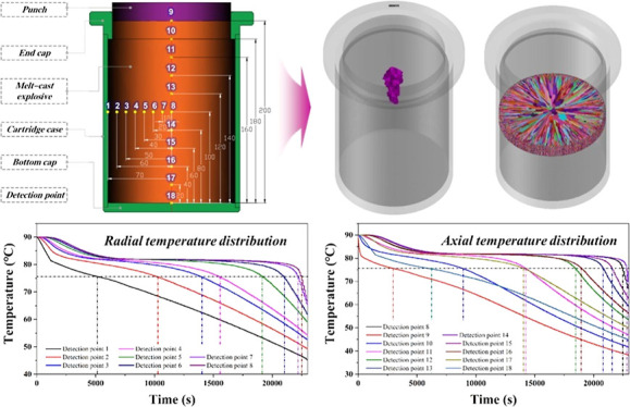
The treatment system during the explosive melting and casting process consists of the body mold and the molding head. Meanwhile, a body mold with an inner diameter of 140 mm and a height of 200 mm was used to simulate the melt-cast explosive solidification for a charge requirement of 5 kg/round. The geometric model and computational grid are shown in Figure 2. In this study, both the mold and explosive models use a tetrahedral grid with a total number of approximately 350,000, and the test results showed that a further increase in the grid number did not affect the simulation results.
Figure 2.

Geometric model and computational grid of the solidification treatment system.
3.3. Boundary Conditions
During charging, the molten slurry was poured into the body mold in the insulation oven, and then the feeding pressure was applied to the top layer of the slurry using the molding head. After the shell insulation was stopped, the slurry was allowed to cool naturally at room temperature (25 °C). Afterward, the metallic head, made of the same material as the body, moved up and down with the change in liquid level to keep the feeding pressure constant and prevent defects formed by slurry feeding in natural solidification. Therefore, considering the effects of pressure on grain molding quality, the low-pressure casting model was chosen, and the ambient pressure was set to 1 atm (atmospheric pressure); other process parameters are shown in Table 2.
Table 2. Boundary Conditions of Simulation of Melt-Cast Explosive Solidification.
| parameters | TNT-based melt-cast explosive | DNAN-based melt-cast explosive |
|---|---|---|
| slurry temperature/°C | 90 | 105 |
| body temperature/°C | 90 | 105 |
| feeding pressure/MPa | 0.5 | 1 |
| heat transfer coefficient/(W·m–2·°C–1) | 20 | 10 |
| head temperature/°C | 80 | 90 |
| water bath height/mm | 180 | 180 |
| water bath time/min | 60 | 60 |
4. Results and Discussion
4.1. Effects of Pressurized Treatment on Solidification Quality
4.1.1. Slurry Solidification Behavior under Constant Pressure
The temperature field and solid/liquid phase distribution at different moments and the solidification time at different locations were analyzed to explore the solidification behavior of slurry in the body under a pressure of 0.5 MPa. The temperature curves of different temperature measurement points in the grain were further calculated, and the results are shown in Figure 3.
Figure 3.

Distribution of solidification time (a), distribution of temperature and solid–liquid phase (b), temperature measurement points (c), and temperature curve (d) of slurry under constant pressure.
Compared with the solidification time of 3.32 h for the outer layer of the grain, the solidification time of the central part of the grain was approximately 6.15 h (Figure 3a). As shown in Figure 3b, the temperature and solid–liquid phase distribution cloud of the TNT-based melt-cast explosive indicated that the high heat conductivity between the outer slurry and the inner wall of the body allowed heat exchange between the system and the environment during the solidification process compared with the inefficient heat transfer between the core slurry, which also led to the regular distribution of temperature and with a decreasing trend toward outside in the axial section. Meanwhile, due to the low heat conductivity of the slurry, the temperature difference between the inside and outside of the grain in the body gradually increased with time. The temperature curves of temperature measurement points distributed along the radial or axial direction revealed that the cooling rate became slower as the slurry moved closer to the core (Figure 3c,d), confirming the layer-by-layer solidification behavior of the slurry under constant pressure. Under the effect of heat transfer, the slurry close to the inner wall of the body and the head was the first to solidify due to the rapid cooling. The phase interface migrated inward via heat transfer and diffusion, leading to the solidification of the slurry from the outside to the inside layer by layer.25
4.1.2. Grain Defect Characteristics under Constant Pressure
Figure 4a shows the predicted shrinkage of the contraction cavity of grains under different pressures. The middle of the final solidification of the grain and the position above it were prone to significant contraction cavity shrinkage defects. This phenomenon is attributed to the volume shrinkage of the slurry during the cooling solidification process. The rapid cooling of the solidification layer outside the slurry significantly hindered the liquid feeding of the core propellant, resulting in a contraction cavity and shrinkage defect in the vicinity of the solidified area. Meanwhile, the static pressure generated during the slurry solidification process also caused certain pressurized feeding. The small liquid static pressure in the upper part of the grain facilitated the formation of different degrees of contraction cavity shrinkage defects close to the inner wall of the head. The distribution of defects in the grain was almost the same under a pressure feeding of 0.5 MPa and no-pressure feeding. However, the addition of feeding pressure can significantly reduce the number of defects at the top of the grain. This reduction is mainly because the application of pressure treatment can maintain the smoothness of the feeding channel by breaking the crystalline skeleton, thus improving the solidification quality of slurry and the density of grains. Theoretically, the greater the pressure, the less the shrinkage of the contraction cavity. However, Figures 3c and 4b show that slurry close to the body and head surfaces solidifies first and forms an inward-growing solidified shell outside the grain. When the solidified shell layer reached a certain thickness, the pressure applied to the head was difficult to transfer to the interior, which prevented the feeding of slurry and caused the formation of core defects.
Figure 4.

Defect characteristics in the grain: (a) distribution of contraction cavity shrinkage defect, (b) internal defect derivation process, and (c) effective stress and heat-cracking simulation.
In addition to the contraction cavity, the difference in temperature distribution and solid–liquid phase transition caused the difference in volume shrinkage of the slurry and generated thermal stress and tissue stress in the solidification process, leading to the formation of defects (such as microcracks) inside the grain. The stress distribution under different pressurized treatments is shown in Figure 4c. Compared with the grain core, the slurry closer to the mold shell and the inner wall of the mold top cover will develop higher stresses during the solidification process, thus increasing the probability of cracks in the orange region of the grain. Additionally, the prediction of heat-cracking defects reveals the difficulty in obtaining high strength and plasticity in the center of the grain during the cooling process due to the initial solidification (Figure 4c). Thus, the production of heat-cracking defects in the final solidification area of the grain was easy due to the blocked solid-state shrinkage. Nevertheless, the defects were concentrated in the interior of the grain, which was directly difficult to observe and needed to be further examined using X-ray, α-ray, or ultrasonic flaw detection. Meanwhile, the mechanical performance of grains can be greatly improved by adjusting the explosive components in the formulation using the micro–nanograding method to obtain higher tensile stress than the equivalent force value, thus preventing the formation of defects.
4.1.3. Slurry Solidification Behavior under Different Heat Transfer Conditions
Previous studies have shown that the heat transfer coefficient between the agent and the mold wall greatly differs under different shell materials. The heat transfer coefficient also has a significant impact on the solidification behavior. Hence, the effect of heat exchange conditions (20, 1000, and 2000 W/m2·K) on the solidification behavior and defect characteristics of the explosive under the slurry/shell treatment temperature (90 °C), and the pressure (0.5 MPa) was comparatively analyzed, and the results are shown in Figure 5. The solidification time of a propellant can be significantly reduced by selecting a shell material with a higher heat transfer coefficient. When the heat transfer coefficient increased from 20 to 1000 W/(m2·K), the solidification time of the slurry was also reduced from 6.36 to 4.89 h, which was 23.1%. Nevertheless, if the heat transfer coefficient of the shell continues to increase, the solidification time will remain the same owing to the low heat transfer efficiency inside the slurry. Meanwhile, the overall variation of defect distributions of the explosive under different heat transfer conditions was small, indicating that the setting of the interface heat transfer coefficient had little effect on the molding defects of grain. Additionally, the formation of defects was attributed to the low intrinsic thermal conductivity of the slurry, the slow cooling rate, and the solidification sequence from the outside to the inside.
Figure 5.

Solidification time (a) and defect characteristics (b) of the grain in cases of different heat transfer coefficients.
4.1.4. Slurry Solidification Behavior at Different Insulation Temperatures
In addition to the heat transfer coefficient, the solidification behavior and defect characteristics of slurry at different insulation temperatures were further analyzed, and the results are shown in Figure 6. As shown in Figure 6a, changing the temperature did not change the solidification behavior of the slurry from outside to inside layer by layer. However, higher temperatures significantly extended the solidification period of the slurry. When the temperature increased from 85 to 100 °C, the time required for complete curing increased from 6.15 to 6.72 h, an increase of 9.3%. The defect distribution clouds in Figure 6b also show that the temperature of the body and head significantly impacts the contraction cavity shrinkage defect inside the grain. As the temperature increased, the slurry tended to shrink more during the solidification process and increased the contraction cavity shrinkage defect, thereby decreasing the grain molding density. Therefore, a lower insulation temperature can be used to reduce the contraction cavity and shrinkage defect and improve the molding quality to ensure the integrity of the filling.
Figure 6.

Solidification time (a) and defect characteristics (b) of grains at different treatment temperatures.
4.2. Effects of Water Bath Curing Technology on Solidification Quality
4.2.1. Slurry Solidification Behavior in an Underwater Bath Environment
In addition to natural cooling, placing the body mold in a water bath where the liquid level rises at a certain rate can effectively influence the solidification behavior of the internal slurry, creating a bottom-up cooling and solidification sequence. For this purpose, the solidification behavior of slurry in a water bath environment under different heat transfer conditions was simulated and analyzed, and the specific results are shown in Figure 7.
Figure 7.

Temperature distribution of slurry in a water bath environment (a), solidification time (b), solid–liquid phase distribution (c), temperature curve (d), and defect characteristics (e).
As shown in Figure 7a–d, the mold could transfer heat through the water with a large interfacial heat transfer coefficient at the location where the water surface could reach. The mold was cooled below the liquid-phase line temperature by placing it in a water bath environment for 10 min and quickly cooled to room temperature during the 1 h water surface climbing process. As a result, the slurry inside the body also formed a bottom-up cooling sequence. The synergistic effect of the head at 80 °C insulation effectively ensured the smooth flow of the feeding channel during the solidification process, thus realizing the layer-by-layer solidification of the bottom slurry and the controllable migration of defects (such as contraction cavity). Additionally, the defect characteristics of grains under different heat transfer effects showed difficulty in increasing the heat transfer coefficient at the interface between the slurry and the body to significantly reduce the number of contraction cavity defects and improve the migration of defects (Figure 7e).
Compared with the pressurized treatment technology, the water bath cooling and head insulation synergistic treatment technology can achieve controllable migration of internal defects by controlling the orderly solidification of the slurry layer by layer, thus effectively eliminating the V-shaped defects inside the grain to further improve its solidification quality.
4.2.2. Slurry Solidification Behavior under Different Water Bath Conditions
In addition to the heat transfer coefficient, the effects of liquid surface height, climbing time, and head temperature on slurry solidification behavior were analyzed by simulating the defect characteristics of slurry under different treatment conditions; the specific conditions are shown in Figure 8.
Figure 8.

Defect characteristics (a) and solidification time (b) of the slurry under different water bath environments.
As shown in Figure 8a, at a head temperature of 80 °C, the defects inside the grain were mainly located above h1 (≈160 mm, 4/5H), and sporadic contraction cavity defects occurred at h3 (≈100 mm, 1/2H) and gradually migrated to above h2 (≈125 mm, 5/8H) with increasing liquid level climbing time. However, when the head temperature decreased to 70 °C, the top slurry prematurely solidified during the cooling process because its insulation temperature was lower than the solid-phase line temperature. The low temperature made the feeding capacity of the slurry difficult to maintain, thereby causing the V-shaped defects at the top of the grain to shift downward significantly.
Compared with the head temperature, the liquid height and climbing time slightly improved the migration effect but significantly reduced the solidification time of the grain. As shown in Figure 8b, when the liquid level climbing time was extended from 15 to 60 min, the time required for complete curing increased from 4.85 to 5.12 h, an increase of 5.6%. Nevertheless, in actual production, the climbing speed of a water bath liquid level should be reduced as much as possible to prevent the higher rising speed of the solid–liquid interface inside the body. Meanwhile, the final liquid level in the water bath curing process should also be lower than the top height of the slurry, thus eliminating the central contraction cavity defects caused by the rapid cooling of the outside of the shell.
4.3. Effects of Thermal-Pressure Coupling Treatment Technology on Solidification Quality
4.3.1. Zero-Defect Solidification Molding of TNT-Based Melt-Cast Explosives
Pressurized treatment can improve the pressure-feeding capacity of the top slurry during the solidification process, and water bath curing can help to achieve axial sequential solidification of the explosive and the uniform migration of its internal defects, while neither can completely eliminate the internal defects of the grain. Following the previous study, the effects of head insulation/thermal-pressure-feeding dual-element treatment based on multitechnology coupling and head insulation/pressurized feeding/water bath cooling ternary treatment on the solidification behavior of TNT-based melt-cast explosive were investigated, which aimed to achieve its high-quality solidification molding. According to the results shown in Figure 9, the use of head insulation/thermal-pressure-feeding dual-element treatment technology significantly changed the order of explosive solidification in the shell mold. Thus, the slurry closer to the head was the last to solidify, ensuring the application of pressurized treatment to the postsolidification slurry, which effectively eliminated the V-shaped shrinkage area of the contraction cavity at the top of the grain. As a result, the simulation results showed only small contraction cavity defects, which were difficult to detect in the radial cross-sectional view. Nevertheless, head insulation improved the grain charge quality and extended the solidification time from 6.15 to 7 h, an increase of 13.8%.
Figure 9.

Temperature curve (a), defect characteristics (b), solidification time (c), and solidification process (d) of slurry under different thermal-pressure coupling treatment technologies.
Compared with the microdefect grain produced through dual-element technology, the head insulation/pressurized feeding/water bath cooling ternary technology can effectively regulate the migration at the phase interface and control the final solidification position at the inner wall of the head, thus achieving zero-defect equal-material manufacturing of the grain. Meanwhile, the solidification duration of slurry in body mold was shortened to 4.8 h using ternary treatment technology with the enhanced heat exchange effect of the water bath environment, which can significantly improve its productivity.
4.3.2. Evolution of the Internal Crystal Morphology of the TNT-Based Explosive under Different Treatment Conditions
During slurry solidification, the microstructure of the grain is related to its nucleation and growth mechanism, and the molding quality of the grain can be significantly improved by controlling its shape and size. Hence, to analyze slurry heat and mass transfer phenomena, the cellular automata-finite element (CAFE) method was used to simulate the solidification and crystallization process at constant pressure. The CAFE method was used to explore the competitive growth of equiaxed and columnar crystals, the transformation of columnar crystals to equiaxed crystals, the formation of columnar crystal areas, and other behavior changes, combined with the nucleation and dendrite growth kinetic models.26−28 The computational regions and related parameters are shown in Figure 10 and Table 3, respectively.
Figure 10.
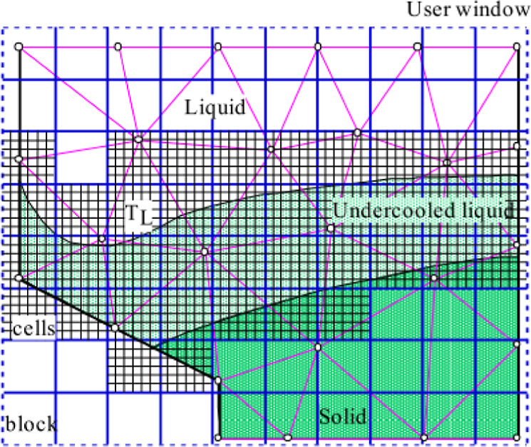
Diagram of solidification area for coupling calculation of the finite element method and cellular automata method.
Table 3. Nucleation Parameters of the TNT-Based Melt-Cast Explosive.
| parameter | variable | value |
|---|---|---|
| body nucleation undercooling degree | ΔTv,max | 4 °C |
| surface nucleation undercooling degree | ΔTs,max | 1 °C |
| a standard variance of the body/surface nucleation undercooling degree | ΔTσ | 1 °C |
| first growth coefficient | a2 | 5.83 × 10⁻⁶ m s–1 °C–1 |
| second growth coefficient | a3 | 1.78 × 10⁻⁶ m s–1 °C–1 |
| body maximum nucleation number | nv | 1 × 10¹⁰/m3 |
| surface maximum nucleation number | ns | 1 × 10⁸/m2 |
As shown in Figure 11, the radial cross section of the molding grain contained three different crystal zones: the outermost thin-layer equiaxed fine crystal zone, the middle columnar crystal zone, and the core equiaxed coarse crystal zone. During the solidification process, the grains closer to the inner wall of the shell and the head surface were the first to nucleate. Owing to the faster cooling rate of the grains, they tend to form equiaxed fine crystal zones with good density. Next, the inward-growing crystals gradually transformed into dendrites and columnar crystals due to the low-heat dissipation efficiency of the slurry and formed coarse equiaxed crystals at the core.
Figure 11.

Effects of pressurized technology on the internal grain growth process.
During solidification, the cooling rate is an important factor affecting the grain morphology and crystallization type. A faster cooling rate can increase the undercooling degree of slurry crystallization, thus increasing the number of nuclei inside the slurry and promoting the growth of small-sized equiaxed crystals. Hence, we simulated the solidification behavior of the slurry in the heat preservation environment of the head at 80 °C by reducing the nucleation undercooling degree to 2 °C and explored the crystal morphological characteristics inside the grain under thermal-pressure coupling conditions. The results are shown in Figure 12 and Table 4. According to the results, the radial cross section of the grain under head insulation conditions mainly comprised equiaxed crystals of different sizes. The closer the grain is to the inner wall of the body, the smaller the size of the grains. This phenomenon was mainly due to the large heat transfer coefficient between the slurry and body mold, resulting in a much higher cooling rate and undercooling degree on the outside of the grain than on the core (Figure 7). The heat transfer coefficient increased the number of nuclei on the outside of the grain and crystal growth rate, thus limiting the growth space of individual crystals to promote the formation of small-sized equiaxed crystals. Compared with the outside of the grain, the core slurry had a longer solidification period due to the insulation head and its low thermal conductivity, which sufficiently promoted the growth of the grain to form equiaxed coarse grain zones. The closer the grain is to the core, the larger the grain size.
Figure 12.

Effects of thermal-pressure coupling technology on the internal crystal morphology, undercooling degree, and nucleation of the grain.
Table 4. Crystal Morphology Parameters of the TNT-Based Melt-Cast Explosive under Thermal-Pressure Coupling Treatment Technology.
| parameter | variable | value |
|---|---|---|
| number of grains | Nb. grain | 5631 |
| statistical area | total surface | 38.2943 cm2 |
| average grain area | mean surface | 0.0068 cm2 |
| minimum area of grains | min surface | 0.0001 cm2 |
| maximum area of grains | max surface | 0.0649 cm2 |
| number of grain boundaries per unit length | NI (Inter/m) | 15.31 cm–1 |
| number of grain boundaries per unit area | Na (Grains/m2) | 147.0453 cm–2 |
| average grain size | mean radius | 0.0663 cm |
4.3.3. Microdefect Solidification Molding of the DNAN-Based Melt-Cast Explosive
Compared with conventional TNT-based melt-cast explosives, the use of DNAN as a liquid-phase carrier with lower shockwave and thermal sensitivities can achieve low vulnerability and high damage effectiveness of warheads while meeting the requirements of blunt-sensitive munitions.29,30 However, lower specific heat and enthalpy of phase transition increase the solidification rate of the DNAN-based melt-cast explosive during cooling, making it easier to form the shrinkage of the contraction cavity due to the blockage of feeding channels during curing.31 Hence, we further investigated the effects of multitechnology coupling-based thermal-pressure technology on the solidification behavior of the DNAN-based melt-cast explosive (Figure 13).
Figure 13.

Solidification process and defect characteristics of DNAN-based melt-casting slurry under different thermal-pressure coupling treatment technologies.
As shown in Figure 13a, because the solid-phase and liquid-phase temperatures of the DNAN-based explosive were more than 10 °C and higher than those of the TNT-based propellant, the continued use of a head insulation temperature of 80 °C resulted in a large contraction cavity inside the grain. As shown in Figure 13b,c, when the temperature of the head increased to 105 °C, a small amount of contraction cavity defects appeared on the top of the grain. The water bath environment had little effect on its charge quality. However, the use of head insulation/pressurized feeding/water bath cooling ternary technology reduced the solidification time of slurry from 12.4 to 10.7 h, a reduction of 13.7%, thus effectively improving its solidification efficiency.
5. Conclusions
In this study, we explored the effects of the treatment methods, including pressurized feeding, head insulation, and water bath cooling, on the molding quality of melt-cast explosives to eliminate grain defects and achieve the preparation of micro-or zero-defect grains for charge defects in TNT- and DNAN-based melt-cast explosives based on the defect derivation mechanism and crystal evolution law. The following conclusions were drawn:
-
(1)
The low intrinsic thermal conductivity of the melt-cast explosive, the slow cooling rate, and the solidification sequence from outside to inside were mainly attributed to the formation of defects. Meanwhile, the use of pressurized treatment technology tended to form a large V-shaped shrinkage area of the contraction cavity in the grain core. The higher the pouring and mold temperature, the larger the defect area.
-
(2)
During the solidification process, a stress concentration region was easily formed close to the inner wall of the body due to uneven volume shrinkage and other problems, thus leading to the formation of microcracks and heat-cracking defects inside the grain. Therefore, it is necessary to further improve the mechanical performance of the grain to improve its internal charge quality. Meanwhile, due to the slurry cooling rate, the radial cross section of the molding grain could form crystal distribution from the outside to the inside, which was the thin-layer equiaxed fine crystal region-columnar crystal region-coarse equiaxed crystal region.
-
(3)
The use of water bath cooling and head insulation collaborative treatment technology can achieve controllable migration of internal defects by controlling the uniform solidification of the slurry layer by layer. Moreover, increasing the head temperature can effectively promote the upward movement of the V-shaped defects at the top of the grain, thus maintaining the defect position above 4/5H and improving the solidification quality.
-
(4)
Furthermore, head insulation-pressurized feeding dual-element treatment technology can effectively regulate the phase interface migration and the final coagulation position at the inner wall of the head, thus realizing microdefect equal-material manufacturing of the grain. Meanwhile, the enhanced heat transfer in the water bath environment with the head insulation/pressurized feeding/water bath cooling ternary treatment technology was used to achieve zero-defect equal-material manufacturing of the grain and shorten the solidification duration of the slurry in the body mold to 4.8 h, thus significantly improving its productivity.
-
(5)
In addition to TNT-based melt-cast explosives, the multitechnology coupling-based thermal-pressure treatment technology was suitable for high-quality solidification molding of the DNAN-based melt-cast explosive. Specifically, the TNT-based melt-cast explosive can be used to obtain corresponding zero-defect TNT-based grains under a pressure treatment of 0.5 MPa, a head insulation temperature of 80 °C, and a water bath environment of 180 mm, while DNAN-based melt-cast explosives can be used to obtain corresponding microdefect DNAN-based grains under a treatment pressure of 1 MPa, a head insulation temperature of 105 °C, and a water bath environment of 180 mm.
Author Contributions
All authors contributed to the study’s conception and design. Material preparation, data collection, and analysis were performed by S.-W.W., C.W., and Y.-L.Z. The first draft of the manuscript was written by S.-W.W., L.X., and G.-M.L. and was reviewed by Y.-B.H., G.-Z.H., and H.G. The research program was formulated by G.-P.Z. and W.J. All authors read and approved the final manuscript.
This work was financially supported by the National Natural Science Foundation of China (nos. 12102194, 22105103, and 22005144), the Natural Science Foundation of Jiangsu Province (BK20200471), and the China Postdoctoral Science Foundation (nos 2020M673527 and 2021M691580).
The authors declare no competing financial interest.
References
- Zong H.; Cong Q.; Zhang T.; Hao Y.; Xiao L.; Hao G.; Zhang G.; Guo H.; Hu Y.; Jiang W. Simulation of printer nozzle for 3D printing TNT/HMX based melt-cast explosive. Int. J. Adv. Des. Manuf. Technol. 2022, 119, 3105–3117. 10.1007/s00170-021-08593-z. [DOI] [Google Scholar]
- Zong H.; Xiao L.; Hao Y.; Gao X.; Wang W.; Yang Y.; Liu Q.; Hao G.; Jiang W. The effect of micro-nano TKX-50 particle gradation on the properties of TNT based castable explosives. J. Energ. Mater. 2021, 1–18. 10.1080/07370652.2021.1984613. [DOI] [Google Scholar]
- Susantez Ç.; Caldeira A.; Loiola B. Natural convection effects on TNT solidification inside a shaped charge mold. Def. Technol. 2022, 18, 1653–1661. 10.1016/j.dt.2021.07.010. [DOI] [Google Scholar]
- Weckerle A.; Coulouarn C.. A step further for the XF® explosive family dedicated to insensitive munitions (IM) 2010 Insensitive Munitions & Energetic Materials Technology Symposium—International Progress in Insensitive Munitions and Energetic Materials: Munich, Germany, 2010.
- Li J.; Tian Y.; Zhang W.; Huang Y. Formation and Prediction of Shrinkage Hole and Shrinkage Porosity in Explosive During Casting Process. Chin. J. Explos. Propellants 2011, 34, 17–20. [Google Scholar]
- Srinivas Kumar A.; Dharma Rao V. Modeling of Cooling and Solidification of TNT based Cast High Explosive Charges. Def. Sci. J. 2014, 64, 339–343. 10.14429/dsj.64.4673. [DOI] [Google Scholar]
- Sun D.; Garimella S.; Singh S.; Naik N. Numerical and Experimental Investigation of the Melt Casting of Explosives. Propellants, Explos., Pyrotech. 2005, 30, 369–380. 10.1002/prep.200500028. [DOI] [Google Scholar]
- Mudryy R.; Singh S.; Stasio D.. Modeling and simulation of melt cast explosives Insensitive Munitions & Energetic Materials Technology Symposium: Melbourne, Australia, 2007.
- Song M. A.; Yuan J.-M.; Liu Y.-C.; Chang S.; Wang J.; Yu Y. Numerical calculation of solidification process of melt-cast explosive in water bath and natural conditions. Chin. J. Explos. Propellants 2013, 36, 54–58. [Google Scholar]
- Yi M.; Zhang M.; Ran J.; Tu X. Solidification control technology of melt-casting charging under water bath curing. Ordnance Ind. Autom. 2019, 38, 14–18. [Google Scholar]
- Sun X.; Cui Q.; Xiong B.; Zhang Y.; Xu Y.; Huang Y. Solidification simulation and verification of modified B explosive. Ordnance Ind. Autom. 2020, 39, 77–81. [Google Scholar]
- Meng J.; Zhang X.; Zhou L. Simulation of solidification process for DNAN-based melt-cast explosives. Acta Armamentarii 2013, 34, 810–814. [Google Scholar]
- Liang G.; Cao H. Prediction of shrinkage porosity and process optimization during explosive casting process. Ordnance Mater. Sci. Eng. 2014, 37, 47–50. [Google Scholar]
- Meng J.-J.; Zhou L.; Zhang X.-R. Effect of pressure of the casting vessel on the solidification characteristics of a DNAN/RDX melt-cast explosive. J. Energ. Mater. 2017, 35, 385–396. 10.1080/07370652.2016.1201172. [DOI] [Google Scholar]
- Witt W.; Sabranski U. A new method for cast-loading mixtures of explosives. Propellants, Explos., Pyrotech. 1979, 4, 1–3. 10.1002/prep.19790040102. [DOI] [Google Scholar]
- Xie Z.; Wang D.; Liu J.; Huang Y. Numerical simulation of melt-cast explosive solidification process. J. Terahertz Sci. Electron. Inf. Technol. 2014, 12, 617–621. [Google Scholar]
- Wang D.; Xie Z.; Sun W.; Huang Y. Solidification simulation of melt-cast explosive under pressurization. Mater. Sci. Forum 2011, 704–705, 71–75. 10.4028/www.scientific.net/msf.704-705.71. [DOI] [Google Scholar]
- Luo Y.; Zhang M.; Yang F.; Li B. Effect of pressure on DNAN solidification process. Sci. Technol. Eng. 2020, 20, 3048–3052. [Google Scholar]
- Yue X.; Zhang H.; Han X.; Liu H.; Wang Y.; Liu H.; Liu P.; Cao H. Process of improved hot mandrel for large length-diameter ratio warhead melting cast. Chin. J. High Pressure Phys. 2021, 35, 015302. [Google Scholar]
- Zhang M.; Zhang B.; Wan D.; Wan L. Study on temperature field changes during casting explosive solidification process. Ordnance Ind. Autom. 2021, 40, 93–96. [Google Scholar]
- Ha H.; Wang T.; Lu Z.; Li Q.; Jin D. Improved thermoplastic charge technique of DNAN-based explosive for warhead. J. Unmanned Undersea Syst. 2020, 28, 209–213. [Google Scholar]
- Jin D.; Wang H.; Niu G.; Wang Q.; Wang S.; Huang W.; Cao S.; Niu L. Charge process of DNAN based melt cast explosive by orthogonal experiments. Chin. J. Energ. Mater. 2014, 22, 804–807. [Google Scholar]
- Peng H.; Yang F.; Wan L.; Ran J.; Huang K.; Rui J. Study on molding process of melt-casting explosive based on non-TNT with high solid content and density. Ordnance Ind. Autom. 2019, 38, 84–87. [Google Scholar]
- Jin D.; Wang Q.; Jiang Q.; Niu G.; Niu L.; Cao S.; Jiang F. Safety analysis for filter press process of a DNAN based melt-cast explosive. Explos. Mater. 2015, 44, 16–21. [Google Scholar]
- Catureba R.; Caldeira A.; Guedes R. Numerical Simulation of the TNT Solidification Process. Def. Sci. J. 2019, 69, 336–341. 10.14429/dsj.69.13536. [DOI] [Google Scholar]
- Liu Y.; Cao H.; Liu S.; Zhang H.; Zhang X.; Xie F. Numerical Simulation of the Internal Crystalline Structure of TNT Melt-Cast Explosive. Chin. J. Energ. Mater. 2019, 27, 363–370. [Google Scholar]
- Gandin C.; Rappaz M. A coupled finite element-cellular automaton model for the prediction of dendritic grain structures in solidification processes. Acta Metall. Mater. 1994, 42, 2233–2246. 10.1016/0956-7151(94)90302-6. [DOI] [Google Scholar]
- Kurz W.; Giovanola B.; Trivedi R. Theory of microstructural development during rapid solidification. Acta Metall. 1986, 34, 823–830. 10.1016/0001-6160(86)90056-8. [DOI] [Google Scholar]
- Fedoroff B.Dictionary of explosives, ammunition and weapons; Smithsonian Libraries and Archives, 1958.
- Trzciński W. A.; Cudziło S.; Dyjak S.; Nita M. A Comparison of the Sensitivity and Performance Characteristics of Melt-pour Explosives with TNT and DNAN Binder. Cent. Eur. J. Energ. Mater. 2014, 11, 443–455. [Google Scholar]
- Liu R. P.; Luo Y. M.; Wang H. X.; Gao J.; Jiang L. Q.; Yang F. Experimental study and numerical simulation on temperature and shrinkage porosity of TNT, DNAN and DNTF during solidification process. Chin. J. Explos. Propellants 2016, 39, 43–52. [Google Scholar]