

Abstract
To enable the accurate reproduction of organs in vitro, and improve drug screening efficiency and regenerative medicine research, it is necessary to assemble cells with single‐cell resolution to form cell clusters. However, a method to assemble such forms has not been developed. In this study, a platform for on‐site cell assembly at the single‐cell level using optically driven microtools in a microfluidic device is developed. The microtool was fabricated by SU‐8 photolithography, and antibodies were immobilised on its surface. The cells were captured by the microtool through the bindings between the antibodies on the microtool and the antigens on the cell membrane. Transmembrane proteins, CD51/61 and CD44 that facilitate cell adhesion, commonly found on the surface of cancer cells were targeted. The microtool containing antibodies for CD51/61 and CD44 proteins was manipulated using optical tweezers to capture HeLa cells placed on a microfluidic device. A comparison of the adhesion rates of different surface treatments showed the superiority of the antibody‐immobilised microtool. The assembly of multiple cells into a cluster by repeating the cell capture process is further demonstrated. The geometry and surface function of the microtool can be modified according to the cell assembly requirements. The platform can be used in regenerative medicine and drug screening to produce cell clusters that closely resemble tissues and organs in vivo.
Keywords: bioMEMS, laser beam applications, microchannel flow, microfabrication
We developed the method for assembling single cells to form a cell cluster that is intended for use as an organ model. Cells are assembled under an optical microscope with single cell resolution by using optically‐driven microstructures with an antibody‐immobilised surface as linkers in a cell‐trapping microfluidic device. Manipulation of single cell using the microtools and assembly of cells is demonstrated in a PDMS microfluidic device.
1. INTRODUCTION
Cell aggregates are three‐dimensional assemblies of cells and have been used as models of organs and tumours in the research fields of pharmaceuticals and regenerative medicine because they behave more similarly to in vivo cells than planar cultured cells. [1, 2, 3, 4, 5, 6] Currently, a number of methods have been developed to produce cell aggregates, including those based on hanging drops [7, 8], non‐adhesive well structures [7, 8, 9], rotating wall vessel [7], and magnetic levitation [7, 8, 9] However, a method to form uniform clusters with multiple types of cells has yet to be developed. Actual organs are composed of multiple types of cells, and their cell composition and arrangement dominate the physiological functions. Thus, in vitro reproduction of the structures will provide further insights of cytoarchitecture, and the accurate model for drug development and regenerative medicine. Conventional spheroid fabrication methods, such as hanging drop method, non‐adhesive wells method, rotating wall vessel method, and magnetic levitation method, are based on bulk solutions of multiple cell types in suspension, and the tissue formed is highly dependent on the self‐assembly capabilities of the cells. [4, 5, 6] In addition, assembly by micropatterning is limited to adhesion to the treated plane, [10] and many 3D cell assembly methods, such as bioprinting with cell‐encapsulating gels, do not have single‐cell level resolution. [11] Assembling cells with single‐cell resolution to form cell clusters will enable accurate reproduction of organs in vitro and improve the efficiency of drug screening and regenerative medicine research.
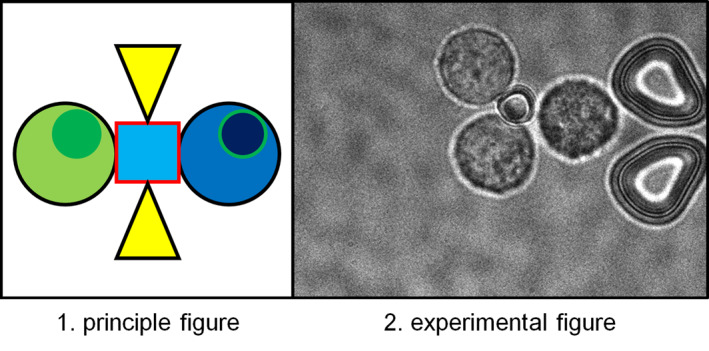
In this paper, we propose a method to form cell clusters from single cells by manipulating microtools with antibodies immobilised on their surfaces using optical tweezers. We previously reported the development of an enzyme‐immobilised microtool for the pinpoint processing of biomolecules, such as a chromosomal DNA molecule. [12] The microtool was fabricated with a negative photoresist SU‐8, which was driven by optical tweezers [13, 14, 15] and had an enzyme‐immobilised surface. SU‐8 allows for the fabrication of 3D microstructures with a high aspect ratio and is known to have high biocompatibility. [16] Using the microtool, on‐site cleavage of chromosomal DNA molecules in a microfluidic device was demonstrated. In this study, we applied this microtool technique to cell manipulation and assembly. By immobilising antibodies against membrane proteins of target cells on the surface of the microstructure, we developed optically driven microtools to capture, manipulate, and assemble specific cells through antigen‐antibody interaction (Figure 1). We aimed to form a cell cluster with controlled alignment and a specific number of cells at single‐cell resolution using this technique. For efficient cell and microtool handling, we also utilised the microfluidic device that allows us to locate the positions of cells and microtools under an optical microscope, where those are kept separated before assembly, preventing nonspecific bindings.
FIGURE 1.
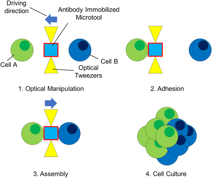
Cell manipulation and assembly using an optically driven microtool with an antibody‐immobilised surface.
We verified the adhesion to cells and cell manipulation in a microfluidic device. We also evaluated the efficiency of cell capture using the antibody‐immobilised microtool in comparison with the microtool without antibody immobilisation. Furthermore, cell assembly at single‐cell resolution using the microtool was demonstrated.
2. METHODS
2.1. Microtool fabrication
A 4‐inch Si wafer divided into four was coated with SU‐8 3010 (MicroChem Corp.). Then, the SU‐8 layer was exposed using a UV mask aligner (MA6/BA6, SÜSS MicroTec) and developed (Figure 2), where 3.0 × 10⁶ microtools were formed at 5 μm intervals. The thickness of SU‐8 defines the height of the microtools. After washing with isopropyl alcohol, the substrate was dried using a supercritical dryer (Rexxam) and baked at 120 °C for 3 h. We fabricated four types of microtools with different cross sections (Figure 3): square, circle, rectangle, and cross‐shaped. The square, circular, and rectangular microtools have the height of 10 μm, and the cross‐shaped 25 μm.
FIGURE 2.
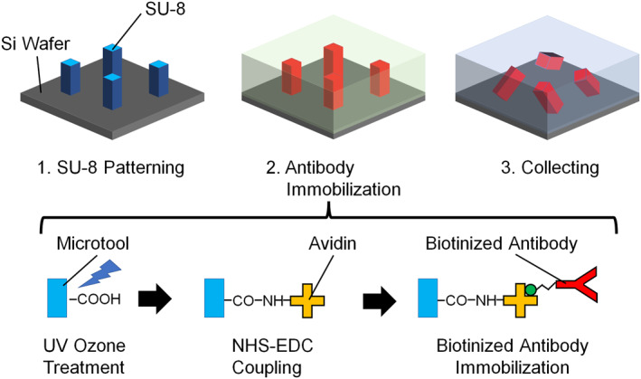
Fabrication process of microtools. The bottom scheme depicts the mechanism of immobilisation of antibodies on the SU‐8 surface.
FIGURE 3.
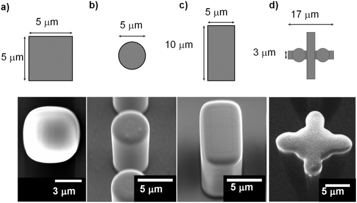
Various shapes of Microtools. Upper: Design. Lower: SEM images. (a) Square, (b) circle, (c) rectangle, and (d) cross‐shaped microtools.
Subsequently, antibody modification to the microtools was performed with the method previously reported for enzyme immobilisation. [12] To introduce carboxyl groups onto the microtool surface, the microtools were treated with UV ozone cleaner [17] (UV253V8, Filgen) at 20 Pa O2 for 30 min. Next, 50 mM N‐hydroxysuccinimide (NHS, Sigma‐Aldrich) and 100 mM 1‐ethyl‐3‐ (3‐dimethylaminopropyl) carbodiimide hydrochloride (EDC, Sigma‐Aldrich) were dispensed onto the wafer and incubated [18] at 20–25°C for 30 min. After the microtools were washed with phosphate‐buffered saline (PBS), 1 mg/ml avidin (NeutrAvidin Protein, Thermo Fisher Scientific)/PBS was dispensed and incubated for 60 min to crosslink the amino groups in the avidins to the carboxyl groups on the SU‐8 surface. After washing with PBS, 1 M ethanolamine (Tokyo Chemical Industry Co., Ltd.) was dispensed and incubated for 30 min to block unreacted groups. It was then washed with PBS again. Thereafter, biotinylated anti‐human CD51/61 antibodies or biotinylated anti‐human CD44 antibodies (BioLegend) were dispensed to a 50 nM concentration in PBS to be immobilised on the microtools through avidin–biotin binding. [19] We collected the microtools in PBS by scratching the wafer surface with a pipette tip.
2.2. Microfluidic device fabrication
The microfluidic device consisted of an inlet, an outlet, the main flow channel between them, and six storage chambers connected to the channel (Figure 4). The channel height was designed to be 25 μm. The main flow channel had 90 cell trap structures formed by pairs of micropillars. The microfluidic device was fabricated with standard polydimethylsiloxane (PDMS) soft lithography.
FIGURE 4.
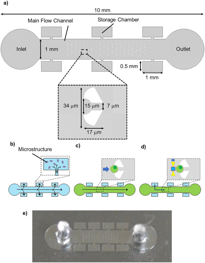
Microchannel for cell‐trapping and assembly. (a) Dimensions of the channel. (b) Introducing microtools into the storage chambers by absorption of air into polydimethylsiloxane (PDMS). (c) Introducing cells and single‐cell trapping. (d) Manipulating microtools by optical tweezers and cell assembly. (e) Photo of the microfluidic device.
The mould was fabricated with SU‐8 3025 and had a thickness of 25 μm. Polydimethylsiloxane (Sylgard184 Dow Chemical Company) was poured onto the mould with a weight ratio of 10:1 (PDMS polymer: curing agent). After curing at 120 °C for 30 min, the PDMS replica was punched to form an inlet and an outlet, and then bonded onto a glass substrate of thickness 0.12–0.17 mm using O2 plasma treatment.
2.3. Cell manipulation
Cell manipulation was conducted in the microfluidic device (Figure 4b–c, Table 1). Prior to the manipulation, the PDMS device was degassed in a vacuum chamber and placed under an inverted optical microscope (IX71, Olympus) equipped with an XY motorised stage and a plate heater (Tokai Hit Co., Ltd.) (Figure 5). The temperature of the PDMS device was maintained at 37 °C using the plate heater and objective lens heater. The image was taken with an electron multiplying CCD camera (C9100‐23B, Hamamatsu Photonics) and a 100× oil immersion objective lens (N.A. 1.40, Olympus).
TABLE 1.
Process flow of cell manipulation experiment
| Process | Condition |
|---|---|
| 1. Degassing of a microfluidic device | 2 h in a vacuum chamber. |
| 2. Tool introduction | Microtool suspension at a concentration of 6.0 × 10⁷ pieces/ml. |
| 3. Washing | A 7.5% (w/v) albumin/D‐PBS at a flow rate of 5 ml/min for 10 min. |
| 4. Cell introduction | HeLa cells at a concentration of 5.0 × 10⁵ cells/ml at a flow rate of 1 ml/min. |
| 5. Washing | DMEM at a flow rate of 100 nL/min. |
| 6. Cell manipulation | A Yb fibre laser (CW 1064 nm). Stage speed (50 mm/s). |
Abbreviation: DMEM, Dulbecco’s modified eagle medium.
FIGURE 5.
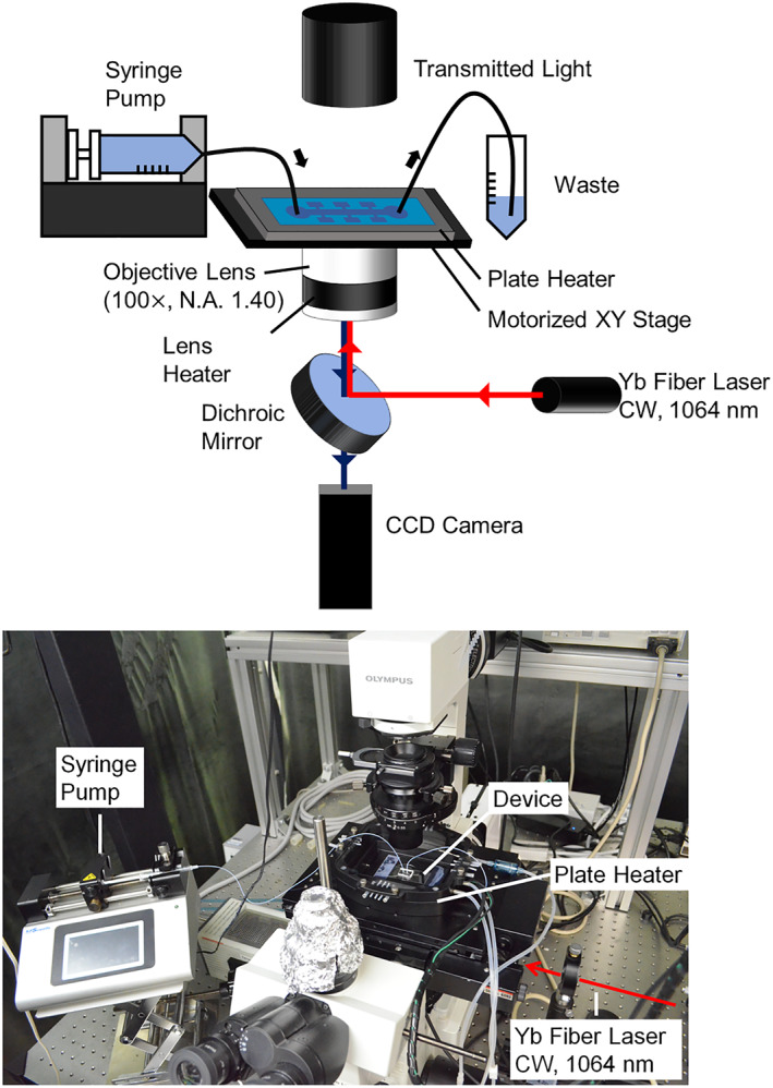
Experimental setup for cell assembly using optical tweezers.
The microtool suspension was introduced from the inlet (Figure 4b). The air trapped in the storage chamber was absorbed into the PDMS as previously reported. [12] This induces flow from the main channel to the storage chambers, which carries the microtools into the chambers. Once the air is removed from the storage chambers, the flow in the main channel does not enter the chambers, where the tools are stored. Subsequently, a syringe pump (Legato111, KD Scientific) was connected to the inlet with a polytetrafluoroethylene tube. A 7.5% (w/v) albumin/D‐PBS (−) solution (Wako) was then introduced into the channel at a flow rate of 5 μL/min for 10 min to wash the flow channel and prevent cell adsorption to the channel surface. [20] Thereafter, a suspension of HeLa cells [21, 22] at a concentration of 5.0 × 10⁵ cells/ml was introduced for trapping at a flow rate of 1 μL/min (Figure 4c). The channel was washed with Dulbecco's modified eagle medium (Gibco, DMEM, low glucose, pyruvate, Thermo Fisher Scientific) at a flow rate of 100 nL/min.
A Yb fibre laser (CW 1064 nm, PYL‐5‐1064.LP, IPG PHOTONICS) was introduced and focussed on the observation plane through the objective lens for the operation of the optical tweezers. The laser power between the lens and the PDMS device was 6.2 mW. In this configuration, the laser trap point was fixed, whereas the device was moved using the motorised XY stage. One of the tools in the storage chamber was trapped by optical tweezers and driven at a speed of 50 μm/s through the channel to the cell trapping location.
3. RESULTS AND DISCUSSION
3.1. Microtools
The microtools were successfully fabricated (Figure 3) and recovered in aqueous solution at a concentration of 6.5 × 10⁷ pieces/ml. These were trapped with optical tweezers, where the directions of their heights were aligned along the direction of the laser propagation, enabling us to define the orientation of the microtools simultaneously with a single beam trap. [13, 14, 15, 23].
3.2. Single‐cell capture and manipulation
Cell capture and manipulation experiments were first performed using CD51/61 antibody‐immobilised microtools and HeLa cells (Figure 6, Supplementary movie S1). CD51/61 is a membrane protein, called integrin aVb3, and is known to bind to many extracellular matrices. [24] The membrane proteins are expressed in HeLa cells. [25, 26] The laser‐operated circular microtool was brought into contact with a trapped HeLa cell and held for 10 s, then the microtool was moved away from the trap structure (manipulation speed: 50 μm/s). As a result, the microtool and the cell were left adjacent to each other and were manipulated together using the optical tweezers.
FIGURE 6.
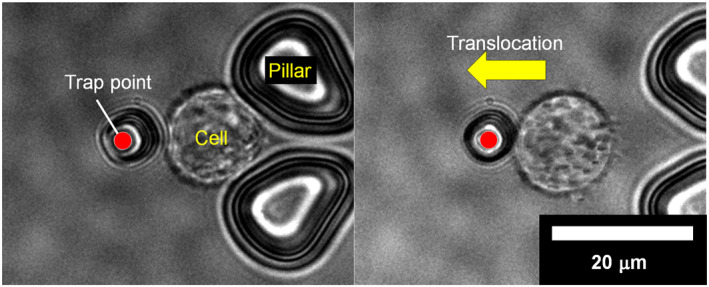
Cell manipulation with a microtool. Left: An optically driven microtool with CD51/61 antibodies in contact with a trapped cell. Right: Translocation of the cell through the microtool.
The result shows that an antibody‐immobilised microtool adheres to a trapped cell within a contact time of less than 10 s, and that the cell captured by the microtool can be manipulated by the optical tweezers. The processing time of 10 s is sufficient for cell assembly; this is a shorter duration than that of the previous studies on cell assembly. [27, 28].
3.3. Efficiency of cell capture
The efficiency of cell capture was evaluated using microtools with various surface conditions. We brought a microtool in contact with a Hela cell for 5 s, and moved it to confirm the adhesion. The number of successful trials of cell adhesion were compared to the number of total trials. The number of the trials was 20 for two surface treatments: CD44 antibody immobilisation and ethanolamine modification without antibody‐immobilisation (negative control) (Figure 7). CD44 is a membrane protein, called hyaluronan receptor, [29] which is also expressed in a HeLa cell.
FIGURE 7.
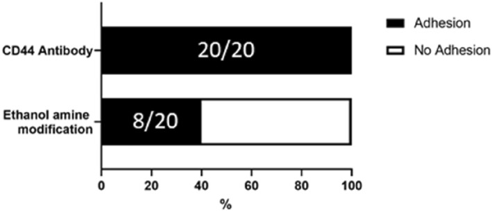
Comparison of adhesion efficiency between two surface treatments on microtools. The numbers in the bars show the number of the trials in the form of (successful adhesion)/(total trial).
The results show that the ethanolamine tool having no antibody brought 40% efficiency of cell capture, which may be induced by nonspecific adsorption on the cell membrane, indicating the necessity of surface modification for cell reliable adhesion. In contrast to that, the antibody‐immobilised microtools showed 100% cell capture rate, indicating that the antibody–antigen binding is reliable for on‐site cell capture and handling.
Furthermore, we compared the HeLa cells with undifferentiated human induced‐pluripotent stem (hiPS) cells using CD44 antibody‐immobilised tools to evaluate the specificity of the tools for cell type (Figure 8). Undifferentiated hiPS cells are negative for CD44 antigen. [30] Therefore, the adhesion induced by antigen‐antibody interaction can be verified by comparing the adhesion rates of these two cell types. The results showed that there was a significant difference in the cell capture rate depending on the cell type. After 5 s of contact, HeLa cells and hiPS cells showed 100% and 20% adhesion rates, respectively. These results indicate that the tools used in this study adhered to the cells through antigen‐antibody interaction, suggesting that the specificity of antibodies can allow the selective handling of target cell type.
FIGURE 8.
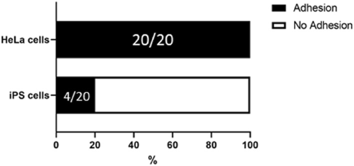
Comparison of adhesion efficiency between 2 cell types. The numbers in the bars show the number of the trials in the form of (successful adhesion)/(total trial).
3.4. Cell assembly
Cell assembly was demonstrated using the microtools and HeLa cells (Figure 9a, CD51/61 antibody microtool and Figure 9b, CD44 antibody microtool). One of the tools in the storage chamber was driven by optical tweezers and brought into contact with a cell in the trap section. This process was repeated to form a cell cluster. In the square microtool experiment, three cells were assembled (Figure 9a), and in the cross‐shape microtool experiment, four cells were assembled (Figure 9b). These results show that the microtools can function as scaffolds for cell assembly. The design flexibility of the microtool potentially allows us to align individual cells into a cell cluster with desired positions and with a specific number of cells. There are several studies that have observed cell‐cell interactions and co‐culture micro‐environments by assembling cells, including those based on polymer solution, [28] and cell surface treatment. [31] The technique proposed here has advantages in terms of its assembly speed (i.e., ∼5 s) and selective cell capture and handling by antibody function.
FIGURE 9.
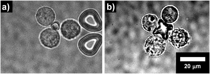
Cell assembly with microtools. (a) 3‐cell assembly with a square microtool. (b) 4‐cell assembly with a cross‐shape section microtool.
Additionally, we performed the assembly in two different cell types using HeLa cells expressing GFP‐tagged histone H2B (HeLa‐H2B‐GFP) and MDA‐MB‐231 cells (Figure 10a). We further demonstrated the assembly with multiple HeLa cells and tools (Figure 10b). These results indicate that the tools can be used for the complex assembly of multiple types of cells, multiple cells, and tools.
FIGURE 10.
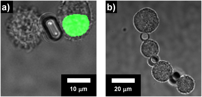
Cell assembly with microtools. (a) Assembly of a HeLa‐H2B‐GFP (left) and a MDA‐MB‐231 cell (right). The HeLa‐H2B‐GFP cell shows fluorescence in the cell nucleus. (b) 4‐cell straight assembly of Hela cells with 3‐microtools.
Cell assembly with this technique will allow us to place heterotypic cells in a cluster with controlled alignment. Such manipulation will be a useful tool for the analysis of cell‐cell interactions in a cell cluster. [32, 33, 34] Successive cell capturing can form larger cell aggregates that will lead to the reproduction of in vivo tissue structures. Although the optical handling has high precision to a nanometre scale, it still limits the 3D manipulation for the movement of the wider XYZ range. Therefore, to achieve the assembly of a larger structure that comprises many cells, additional techniques would be required to build up cell clusters, including 3D cell culture. Although it still depends on the self‐organisation of cells, 3D cell culture that starts from a cell cluster assembled by the microtool is a facile approach to form a larger structure. Currently, the response of two or more types of cells in 3D culture has been observed by spheroid fusion [35] or co‐culture, [36] although the alignment and number of the cells cannot be controlled. It is expected that cell clusters assembled by the microtools as “seeds” for 3D culture will produce cell aggregates closer to the desired composition and could be applied to in vitro organ models.
4. CONCLUSIONS
Cell assembly at single cell resolution is a technical challenge to realise accurate reproduction of organs. We demonstrated on‐site single cell assembly: cell capture, manipulation, and assembly using optically driven microtools on which antibodies to membrane proteins are immobilised. We evaluated the effect of surface condition of the microtools for efficient cell capture. The results confirmed the adhesion caused by antibodies, showing that the antibody immobilised microstructure is a reliable tool for single cell assembly. The assembly of HeLa cells was demonstrated using the fabricated microtools. Our development of the microtools will facilitate effective cell assembly at the single‐cell level and the production of designed cell aggregates. Further developments of cell assembly to form larger and 3‐dimensional cell structures will lead to the in vitro reproduction of organs.
AUTHOR CONTRIBUTIONS
K. T. designed the study. S. M. and T. I. conducted the experiments. K. T., S. M., and T. I. wrote the manuscript. H. T., F. S., and K. T. contributed to the discussion of the microfabrication. All authors discussed the results and contributed to the final manuscript.
CONFLICTS OF INTEREST
There are no conflicts to declare.
PERMISSION TO REPRODUCE MATERIALS FROM OTHER SOURCES
None.
Supporting information
Supporting Information S1
Supporting Information S2
ACKNOWLEDGEMENTS
This work was supported by the JST‐PRESTO (grant number JPMJPR14FB); JST‐FOREST (grant number JPMJFR212D); and JSPS KAKENHI (20H02118) of the Ministry of the Education, Culture, Sports, Science, and Technology (MEXT), and Nakatani Foundation.
Mori, S. , et al.: Optically driven microtools with an antibody‐immobilised surface for on‐site cell assembly. IET Nanobiotechnol. 17(3), 197–203 (2023). 10.1049/nbt2.12114
DATA AVAILABILITY STATEMENT
The data that support the findings of this study are available from the corresponding author upon reasonable request.
REFERENCES
- 1. Abbott, A. : Biology's new dimension. Nature 424(6951), 870–872 (2003). 10.1038/424870a [DOI] [PubMed] [Google Scholar]
- 2. Sutherland, R.M. : Cell and environment interactions in tumor microregions: the multicell spheroid model. Science 240(4849), 177–184 (1988). 10.1126/science.2451290 [DOI] [PubMed] [Google Scholar]
- 3. Fatehullah, A. , Tan, S.H. , Barker, N. : Organoids as an in vitro model of human development and disease. Nat. Cell Biol. 18(3), 246–254 (2016). 10.1038/ncb3312 [DOI] [PubMed] [Google Scholar]
- 4. Lin, R.Z. , Chang, H.Y. : Recent advances in three‐dimensional multicellular spheroid culture for biomedical research. Biotechnol. J. 3(9‐10), 1172–1184 (2008). 10.1002/biot.200700228 [DOI] [PubMed] [Google Scholar]
- 5. Hirschhaeuser, F. , et al.: Multicellular tumor spheroids: an underestimated tool is catching up again. J. Biotechnol. 148(1), 3–15 (2010). 10.1016/j.jbiotec.2010.01.012 [DOI] [PubMed] [Google Scholar]
- 6. Kelm, J.M. , et al.: Method for generation of homogeneous multicellular tumor spheroids applicable to a wide variety of cell types. Biotechnol. Bioeng. 83(2), 173–180 (2003). 10.1002/bit.10655 [DOI] [PubMed] [Google Scholar]
- 7. Wang, A. , Madden, L.A. , Paunov, V.N. : Advanced biomedical applications based on emerging 3D cell culturing platforms. J. Mater. Chem. B 46, 10487–10501 (2020). 10.1039/d0tb01658f [DOI] [PubMed] [Google Scholar]
- 8. Poornima, K. , et al.: Front. Oncol. 12, 891673 (2022). 10.3389/fonc.2022.891673.8 [DOI] [PMC free article] [PubMed] [Google Scholar]
- 9. Jensen, C. , Teng, Y. Front. Mol. Biosci. 7, 33 (2020). 10.3389/fmolb.2020.00033 [DOI] [PMC free article] [PubMed] [Google Scholar]
- 10. Falconnet, D. , et al.: Surface engineering approaches to micropattern surfaces for cell‐based assays. Biomaterials 27(16), 3044–3063 (2006). 10.1016/j.biomaterials.2005.12.024 [DOI] [PubMed] [Google Scholar]
- 11. Miri, A.K. , et al.: Effective bioprinting resolution in tissue model fabrication. Lab Chip 19(11), 2019–2037 (2019). 10.1039/c8lc01037d [DOI] [PMC free article] [PubMed] [Google Scholar]
- 12. Masuda, A. , et al.: On‐site processing of single chromosomal DNA molecules using optically driven microtools on a microfluidic workbench. Sci. Rep. 11(1), 7961 (2021). 10.1038/s41598-021-87238-3 [DOI] [PMC free article] [PubMed] [Google Scholar]
- 13. Terao, K. , et al.: Characterisation of optically driven microstructures for manipulating single DNA molecules under a fluorescence microscope. IET Nanobiotechnol. 10(3), 124–128 (2016). 10.1049/iet-nbt.2015.0036 [DOI] [PMC free article] [PubMed] [Google Scholar]
- 14. Terao, K. , Washizu, M. , Oana, H. : On‐site manipulation of single chromosomal DNA molecules by using optically driven microstructures. Lab Chip 8, 1280–1284 (2008). 10.1039/b803753a [DOI] [PubMed] [Google Scholar]
- 15. Inukai, R. , et al.: Capture and elongation of single chromosomal DNA molecules using optically driven microchopsticks. Biomicrofluidics 14(4), 044114 (2020). 10.1063/5.0017727 [DOI] [PMC free article] [PubMed] [Google Scholar]
- 16. Nemani, K.V. , et al.: In vitro and in vivo evaluation of SU‐8 biocompatibility. Mater. Sci. Eng. C 33(7), 4453–4459 (2013). 10.1016/j.msec.2013.07.001 [DOI] [PMC free article] [PubMed] [Google Scholar]
- 17. Delplanque, A. , et al.: UV/ozone surface treatment increases hydrophilicity and enhances functionality of SU‐8 photoresist polymer. Appl. Surf. Sci. 314(30), 280–285 (2014). 10.1016/j.apsusc.2014.06.053 [DOI] [Google Scholar]
- 18. Rusmini, F. , Zhong, Z. , Feijen, J. : Protein immobilization strategies for protein biochips. Biomacromolecules 8(6), 1775–1789 (2007). 10.1021/bm061197b [DOI] [PubMed] [Google Scholar]
- 19. Hsu, S.M. , Raine, L. , Fanger, H. : Use of avidin‐biotin‐peroxidase complex (ABC) in immunoperoxidase techniques: a comparison between ABC and unlabeled antibody (PAP) procedures. J. Histochem. Cytochem. 29(4), 577–580 (1981). 10.1177/29.4.6166661 [DOI] [PubMed] [Google Scholar]
- 20. Wong, L. , Ho, C.M. : Surface molecular property modifications for poly(dimethylsiloxane) (PDMS) based microfluidic devices. Microfluid. Nanofluidics 7(3), 291 (2009). 10.1007/s10404-009-0443-4 [DOI] [PMC free article] [PubMed] [Google Scholar]
- 21. Masters, J.R. : HeLa cells 50 years on: the good, the bad and the ugly. Nat. Rev. Cancer 2(4), 315–319 (2002). 10.1038/nrc775 [DOI] [PubMed] [Google Scholar]
- 22. Ma, H.L. , et al.: Multicellular tumor spheroids as an in vivo–like tumor model for three‐dimensional imaging of chemotherapeutic and nano material cellular penetration. Mol. Imag. 11(6), 487–498 (2012). 10.2310/7290.2012.00012 [DOI] [PubMed] [Google Scholar]
- 23. Gauthier, R.C. , Ashman, M. , Grover, C.P. : Experimental confirmation of the optical‐trapping properties of cylindrical objects. Appl. Opt. 38(22), 4861–4869 (1999). 10.1364/AO.38.004861 [DOI] [PubMed] [Google Scholar]
- 24. Humphries, J.D. , Byron, A. , Humphries, M.J. : Integrin ligands at a glance. J. Cell Sci. 119(19), 3901–3903 (2006). 10.1242/jcs.03098 [DOI] [PMC free article] [PubMed] [Google Scholar]
- 25. Giner‐Casares, J.J. , et al.: Plasmonic surfaces for cell growth and retrieval triggered by near‐infrared light. Angew. Chem. Int. Ed. 55(3), 974–978 (2016). 10.1002/anie.201509025 [DOI] [PMC free article] [PubMed] [Google Scholar]
- 26. Kirkham, G.R. , et al.: Precision assembly of complex cellular microenvironments using holographic optical tweezers. Sci. Rep. 5(1), 8577 (2015). 10.1038/srep08577 [DOI] [PMC free article] [PubMed] [Google Scholar]
- 27. Gou, X. , et al.: Cell adhesion manipulation through single cell assembly for characterization of initial cell‐to‐cell interaction. Biomed. Eng. Online 14(1), 114 (2015). 10.1186/s12938-015-0109-2 [DOI] [PMC free article] [PubMed] [Google Scholar]
- 28. Yamazaki, T. , et al.: Construction of 3D cellular composites with stem cells derived from adipose tissue and endothelial cells by use of optical tweezers in a natural polymer solution. Materials 12(11), 1759 (2019). 10.3390/ma12111759 [DOI] [PMC free article] [PubMed] [Google Scholar]
- 29. Aruffo, A. , et al.: CD44 is the principal cell surface receptor for hyaluronate. Cell 61(7), 1303–1313 (1990). 10.1016/0092-8674(90)90694-a [DOI] [PubMed] [Google Scholar]
- 30. Quintanilla, R.H. , et al.: CD44 is a negative cell surface marker for pluripotent stem cell identification during human fibroblast reprogramming. PLoS One 9(1), e85419 (2014). 10.1371/journal.pone.0085419 [DOI] [PMC free article] [PubMed] [Google Scholar]
- 31. Fitzgerald, K.A. , et al.: Ras, protein kinase cζ, and IκB kinases 1 and 2 are downstream effectors of CD44 during the activation of NF‐κB by hyaluronic acid fragments in T‐24 carcinoma cells. J. Immunol. 164(4), 2053–2063 (2000). 10.4049/jimmunol.164.4.2053 [DOI] [PubMed] [Google Scholar]
- 32. Park, T.H. , Shuler, M.L. : Integration of cell culture and microfabrication Technology. Biotechnol. Prog. 19(2), 243–253 (2003). 10.1021/bp020143k [DOI] [PubMed] [Google Scholar]
- 33. Desroches, B.R. , et al.: Functional scaffold‐free 3‐D cardiac microtissues: a novel model for the investigation of heart cells. Am. J. Physiol. Heart Circ. Physiol. 302(10), H2031–H2042 (2012). 10.1152/ajpheart.00743.2011 [DOI] [PMC free article] [PubMed] [Google Scholar]
- 34. Zervantonakis, I.K. , et al.: Microfluidic devices for studying heterotypic cell‐cell interactions and tissue specimen cultures under controlled microenvironments. Biomicrofluidics 5(1), 13406 (2011). 10.1063/1.3553237 [DOI] [PMC free article] [PubMed] [Google Scholar]
- 35. Birey, F. , et al.: Assembly of functionally integrated human forebrain spheroids. Nature 545(7652), 54–59 (2017). 10.1038/nature22330 [DOI] [PMC free article] [PubMed] [Google Scholar]
- 36. Lazzari, G. , et al.: Multicellular spheroid based on a triple co‐culture: a novel 3D model to mimic pancreatic tumor complexity. Acta Biomater. 78, 296–307 (2018). 10.1016/j.actbio.2018.08.008 [DOI] [PubMed] [Google Scholar]
Associated Data
This section collects any data citations, data availability statements, or supplementary materials included in this article.
Supplementary Materials
Supporting Information S1
Supporting Information S2
Data Availability Statement
The data that support the findings of this study are available from the corresponding author upon reasonable request.