Abstract
This paper introduces a sharp-interface approach to simulating fluid-structure interaction (FSI) involving flexible bodies described by general nonlinear material models and across a broad range of mass density ratios. This new flexible-body immersed Lagrangian-Eulerian (ILE) scheme extends our prior work on integrating partitioned and immersed approaches to rigid-body FSI. Our numerical approach incorporates the geometrical and domain solution flexibility of the immersed boundary (IB) method with an accuracy comparable to body-fitted approaches that sharply resolve flows and stresses up to the fluid-structure interface. Unlike many IB methods, our ILE formulation uses distinct momentum equations for the fluid and solid subregions with a Dirichlet-Neumann coupling strategy that connects fluid and solid subproblems through simple interface conditions. As in earlier work, we use approximate Lagrange multiplier forces to treat the kinematic interface conditions along the fluid-structure interface. This penalty approach simplifies the linear solvers needed by our formulation by introducing two representations of the fluid-structure interface, one that moves with the fluid and another that moves with the structure, that are connected by stiff springs. This approach also enables the use of multi-rate time stepping, which allows us to use different time step sizes for the fluid and structure subproblems. Our fluid solver relies on an immersed interface method (IIM) for discrete surfaces to impose stress jump conditions along complex interfaces while enabling the use of fast structured-grid solvers for the incompressible Navier-Stokes equations. The dynamics of the volumetric structural mesh are determined using a standard finite element approach to large-deformation nonlinear elasticity via a nearly incompressible solid mechanics formulation. This formulation also readily accommodates compressible structures with a constant total volume, and it can handle fully compressible solid structures for cases in which at least part of the solid boundary does not contact the incompressible fluid. Selected grid convergence studies demonstrate second-order convergence in volume conservation and in the pointwise discrepancies between corresponding positions of the two interface representations as well as between first and second-order convergence in the structural displacements. The time stepping scheme is also demonstrated to yield second-order convergence. To assess and validate the robustness and accuracy of the new algorithm, comparisons are made with computational and experimental FSI benchmarks. Test cases include both smooth and sharp geometries in various flow conditions. We also demonstrate the capabilities of this methodology by applying it to model the transport and capture of a geometrically realistic, deformable blood clot in an inferior vena cava filter.
Keywords: Fluid-structure interaction, nonlinear continuum mechanics, immersed Lagrangian-Eulerian method, immersed interface method, inferior vena cava filter
1. Introduction
Computer modeling and simulation are powerful tools for analyzing nonlinear fluid-structure interaction (FSI) that can include large deformations and displacements of flexible bodies immersed in fluid. Well-known approaches to FSI include partitioned formulations that use separate descriptions of the fluid and solid subregions. One common discretization approach for such formulations is to use non-overlapping, body-fitted domain discretizations [1, 2]. Body-fitted discretizations facilitate the specification of precise boundary conditions, which can resolve flow features up to the fluid-structure interface. However, body-fitted approaches require complex and potentially expensive mesh manipulations via grid generation, regeneration, and mesh morphing [3]. Further, grid regeneration generally will require interpolating the computed solution to a new mesh which [4, 5], can introduce errors and instabilities. Immersed formulations, such as Peskin’s immersed boundary (IB) method [6–8], are alternatives to body-fitted approaches that avoid the need to use conforming discretizations of the fluid and structure. Immersed methods thereby can circumvent the mesh generation difficulties of body-fitted approaches and facilitate very large structural deformations. Immersed methods also can simplify developing efficient structured-grid solvers. The key challenge in these methods, however, is related to developing effective and accurate coupling operators and boundary conditions that link the Eulerian and Lagrangian variables; see a recent review by Griffith and Patankar [9] along with those by Peskin [8], Mittal and Iaccarino [10], and Sotiropoulos and Yang [11]. This paper extends our earlier work to integrate partitioned and immersed approaches to FSI by generalizing our recently developed immersed Lagrangian-Eulerian formulation for fluid-rigid structure interaction [12] to problems involving flexible structures described by nonlinear elastic material models. To do so, in this work, the equations of motion for the rigid body are replaced by the equations of elastodynamics. We introduce mathematical formulations for both incompressible and compressible structures. Numerical methods for the incompressible case adopt a nearly incompressible formulation as a penalty method for exactly incompressible structural models.
The immersed boundary method was created to treat FSI problems involving thin flexible interfaces. Subsequent extensions were developed to treat structures of finite thickness, most of which use integral transforms with regularized Dirac delta function kernels to connect the Eulerian and Lagrangian variables [8, 13–16]. In the original IB method, fiber-based elasticity models describe the elasticity of the immersed structure, and regularized Dirac delta functions connect the Eulerian and Lagrangian variables. These regularized delta functions prolong structural forces to the Cartesian grid and restrict Cartesian grid velocities onto the Lagrangian mesh [6]. The immersed finite element (IFE) method is an extension of the IB method that uses finite element approximations for both the Lagrangian and the Eulerian equations with a class of kernel functions based on reproducing kernel particle methods (RKPM) for the fluid-solid coupling [17, 18]. Boffi et al. [19] presented a fully variational IB formulation that allows for a nonlinear mechanics-based description of the Lagrangian structure within the framework of large-deformation continuum mechanics. Regularization in this formulation is achieved implicitly through the finite element (FE) basis functions. The immersed structural potential method of Gil et al. [20, 21] uses a meshless method for the description of hyperelastic immersed structure and a family of spline-based kernel functions for interaction between fluid and solid. Devendran and Peskin [22] developed an energy-based IB method that allows for a nodal approximation of elastic forces directly calculated from energy functional without the use of stress tensors, though in the process, analytical calculations of the strain energy functional derivatives with respect to the coefficients of the discretized displacement field in the FE space are required. Griffith and Luo introduced a hybrid finite difference/finite element approach that uses a FE discretization of the solid structure while retaining a finite difference scheme for the Eulerian variables on the Cartesian grid [23]. As in the conventional IB method, a regularized delta function is used in approximations to the integral transforms, but the nodal velocity of the immersed structure is obtained by projecting an intermediate Lagrangian velocity field onto the finite element space. Recent work demonstrated that this method is equivalent to the method of Devendran and Peskin for specific choices of FE basis functions and quadrature rules [24]. Mortar methods have also been used to treat interface conditions in immersed formulations [25–27]. In such approaches, information transfer between fluid and solid subdomains is done in a weak sense, by using an -projection operator. Methods based on distributed Lagrange multipliers (DLM) form another class of immersed formulations, and since their original development by Glowinski et al. [28, 29], different variations of this approach have been reported for fluid-flexible structure interaction [30–34]. To our knowledge, except for our earlier work on rigid-body FSI [12], all existing DLM formulations use volumetric coupling schemes to connect the fluid and solid variables. Other immersed formulations for FSI include the moving least square direct forcing immersed boundary method [35–37] and fully Eulerian approaches based on finite difference [38–40] or finite element [41, 42] techniques. In all of these approaches, the equations of fluid dynamics are solved throughout the computational domain, including in the solid subregion. Formulations that use a Cartesian grid for the fluid domain but do not extend the fluid solution to the interior of the solid domain have been developed based on the extended finite element method (XFEM) [43–45], overlapping Chimera-like methods [46–49], cut-cell methods [50], and the cut-finite element method [51, 52]. These methods can be considered immersed in that they use a fixed Eulerian grid, although to increase accuracy near the fluid-structure interface, they typically adopt approaches such as local modifications to the finite difference stencils that make them similar to body-fitted discretizations.
As in our earlier work [12], our goal is to create a numerical scheme with the geometrical and domain solution flexibility of the IB method and an accuracy comparable to body-fitted approaches for which sharp resolution of flows and stresses is achieved up to the fluid-structure interface. Unlike many IB methods, our ILE approach uses distinct momentum equations for the fluid and solid subregions, and it uses a Dirichlet-Neumann coupling strategy that connects fluid and solid subproblems through interface conditions. Our mathematical formulation can treat exactly incompressible structures, as in conventional IB methods. Unlike standard IB methods, however, it also can readily handle compressible structures with a constant total volume. Further, it can model fully compressible structures that are only partially immersed in fluid, such as if the elastic structure fully encloses an incompressible fluid. To avoid solving monolithic systems of equations that involve both fluid and solid variables, however, we use two distinct representations of the fluid-structure interface: one that moves with the fluid and a second that moves with the structure. These two representations are connected by approximate Lagrange multiplier forces that account for the kinematic interface conditions. Results demonstrate that this simple approach can control discrepancies between the two interface configurations effectively. The deformations of the structure are determined as a result of interplay between the forces of intrinsic stresses associated with the solid constitutive model and the exterior fluid traction forces that are imposed as boundary conditions to the solid domain. Consequently, our approach can be viewed as a DLM scheme that uses interfacial, rather than volumetric, FSI coupling. The dynamics of the volumetric structural mesh are determined using a standard Lagrangian finite element method for large-deformation nonlinear elasticity. We adopt a nearly incompressible solid mechanics formulation for most of the test cases considered in this work. We also demonstrate the method’s ability to model fully compressible structures for cases in which part of the solid boundary does not contact the fluid, such as when the elastic structure fully encloses an incompressible fluid. Our fluid solver relies on an immersed interface method (IIM) for discrete surfaces [53] to impose stress jump conditions along complex interfaces and allows for the use of fast structured-grid solvers for the incompressible Navier-Stokes equations. Previous studies using the IIM have primarily focused on interfaces with prescribed motion [53–56] or on FSI models involving thin elastic membranes [56–60] with simple material descriptions. Our IIM formulation enables us to evaluate exterior fluid traction along fluid-structure interfaces described by surface representations, which facilitates its application to FE models of complex geometries and structural mechanics.
We use both computational and experimental flexible-body FSI benchmarks to assess and validate the robustness and accuracy of the new algorithm. Test cases include two dimensional cases of a soft disk in a lid driven cavity [23, 61], a version of the Turek-Hron benchmark problem [62], and the damped structural instability of a fully enclosed fluid reservoir [63]. We also present results from three-dimensional cases, including a horizontal flexible plate inside a flow phantom based on experimental results proposed by Hessenthaler et al. [64], and a demonstration case applying our methodology to model the transport and capture of a geometrically realistic, deformable blood clot in an inferior vena cava (IVC) filter [65]. IVC filters are cardiovascular devices that are implanted in the IVC, a large vein in the abdomen through which blood flow from the lower extremities returns to the heart. IVC filters capture clots shed from the lower extremities, as can occur in deep vein thrombosis, before they can migrate to the lungs and cause a potentially fatal pulmonary embolism. Modeling the transport and fluid-structure interaction of flexible blood clots in the venous vasculature is critical to computationally predicting the performance of embolic protection devices like IVC blood clot filters.
Numerical tests demonstrate that approximate Lagrange multiplier forces can be constructed to achieve pointwise second-order convergence for the discrepancy between the positions of the two interface representations in our algorithm. We also report at least second-order accuracy in structural volume representing the incompressibility error of the Lagrangian domain. Our time integration scheme is demonstrated to yield second-order accuracy for the structural displacement, and the overall scheme yields between first- and second-order accuracy in a full spatio-temporal convergence study. Additionally, our simulations demonstrate that structures with low and near-equal density ratios are successfully modeled with reasonable time step sizes with no apparent restrictions caused by artificial added mass instabilities. Instabilities due to the artificial added mass effect have been previously reported for weakly coupled FSI schemes with explicit time stepping schemes for systems with low or nearly equal structure-to-fluid density ratios [66–68]. Though no theoretical proof is provided in this work, we hypothesize that the evident robustness of the method to artificial added mass instabilities stems from its consistent treatment of the momentum of the fluid near the fluid-structure interface. Finally, the partitioned formulation also provides the flexibility of using multi-rate time-stepping, which can relax time-step restrictions and boost the computational performance by allowing separate choices of time-step sizes in the fluid and solid mechanics solvers. We demonstrate this capability of the present approach for the simulations of the modified Turek-Hron benchmark and damped structural instability of an enclosed fluid reservoir.
2. Continuous equations of motion
This section presents the partitioned and ILE forms of the equations describing fluid-structure interaction with an immersed elastic body. A conventional partitioned formulation for FSI is outlined in Sec. 2.1 followed by the general ILE formulation in Sec. 2.2. Secs. 2.2.1 and 2.2.2 introduce penalty methods for the ILE formulation that are used in practical computations of incompressible and compressible solid structures, respectively. Sec. 2.3 details the weak formulation of the structural mechanics along with specific material constitutive models used in our numerical tests.
2.1. The partitioned formulation
We consider a physical domain subdivided into time-dependent fluid and structure subdomains, and , indexed by time , so that , with indicating fixed physical coordinates. We first outline the partitioned formulation for an incompressible structure that is fully immersed in an incompressible fluid within a fixed physical domain; see Fig. 1(a). We describe the fluid dynamics in Eulerian form and assume an incompressible Newtonian fluid with uniform density and viscosity . The fluid stress tensor is
| (1) |
in which is the fluid pressure and is the fluid velocity. The structural kinematics are described in Lagrangian form using reference coordinates attached to the structure. We use the motion map to determine the current position of material point at time . The regions meet along the fluid-structure interface, . The equations of motion for the coupled fluid-structure system are
| (2) |
| (3) |
| (4) |
| (5) |
| (6) |
| (7) |
in which is the structural mass density in the reference configuration (constant in time for an incompressible structure) and is the (volumetric) Jacobian determinant associated with the structural deformation, in which is the deformation gradient tensor. In Eq. (7), is the outward unit normal vector pointing into along is the outward normal vector in the reference configuration along , and is the surface Jacobian determinant that converts the surface force density from force per unit area in the current configuration to force per unit area in the reference configuration. is related to the volumetric Jacobian determinant through Nanson’s formula, is the first Piola-Kirchhoff stress tensor, which is defined for an incompressible a hyperelastic material by
| (8) |
Figure 1:
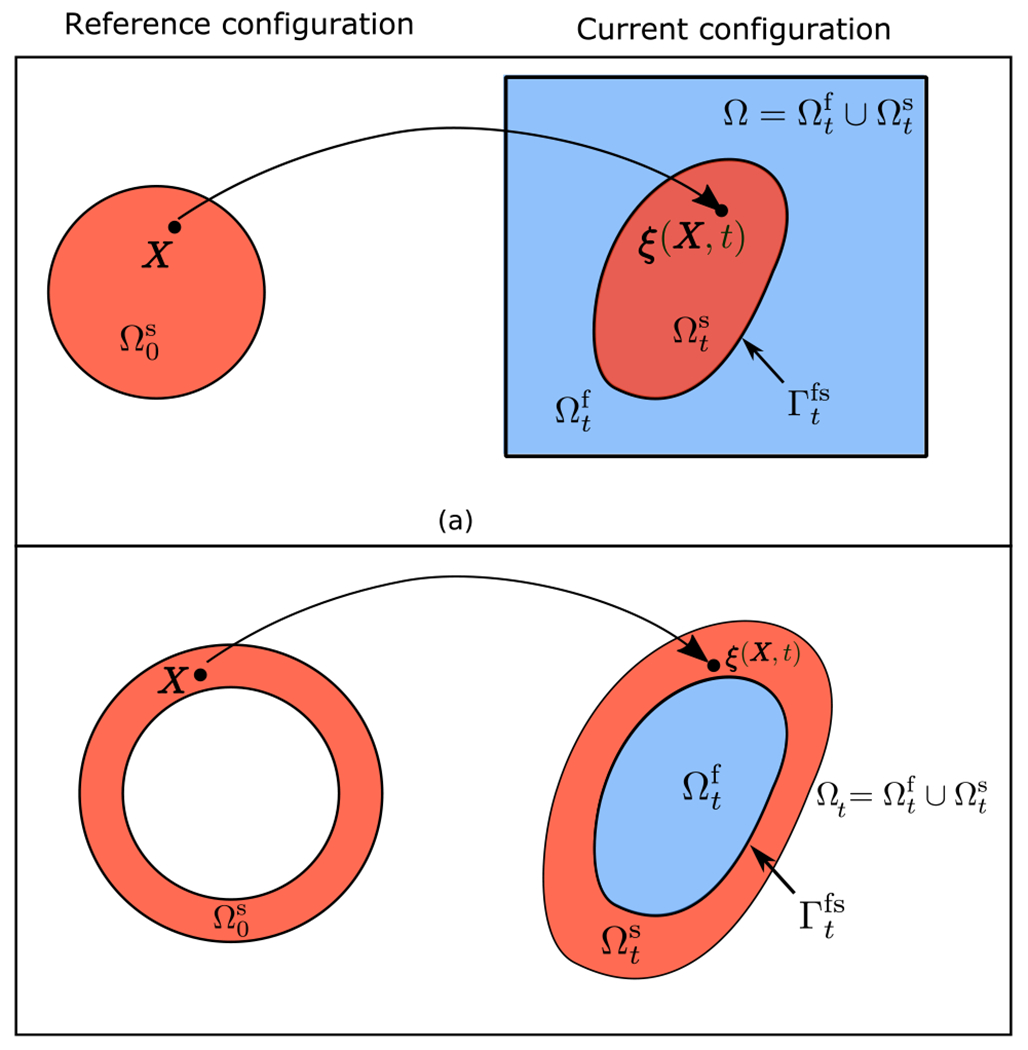
(a) Schematic of the domain including time-dependent fluid and immersed solid subdomains, and , in a partitioned formulation. The solid is described using reference coordinates . Reference and current coordinates are connected by the mapping . (b) Schematic of the partitioned formulation for a model in which the solid structure is not fully immersed in the fluid. In the specific case shown here, the solid structure is a thick shell that encloses the fluid region, but its outer boundary does not come in contact with the fluid. Notice that in this case, the physical domain itself will generally be time dependent
Here, is the strain-energy functional and is the hydrostatic pressure that enforces the incompressibility of the structure. In the aforementioned governing equations, Eqs. (2) and (3) describe the momentum and incompressibility of the fluid, whereas Eqs. (4) and (5) describe the momentum and incompressibility of the structure. Eqs. (6) and (7) respectively account for the kinematic and dynamic conditions at the fluid-structure interface. Eq. (6) describes the no-slip and no-penetration condition at the FSI interface, whereas Eq. (7) describes the force balance along the fluid-solid interface.
It is also possible to consider a partitioned fluid-structure formulation for a system in which the solid domain is only partially in contact with the fluid, as depicted for the non-simply connected ring-shaped solid domain in Fig. 1(b). Note that in this case, the physical domain may be time dependent. In the following section, we will demonstrate how in this case, our ILE coupling allows us to use a fully compressible structural model. For compressible structures, the constraint in Eq. (5) is no longer enforced, and the density of the solid in the current configuration is . Although not considered here, it is also straightforward to relax the incompressibility constraint in the fully immersed case and allow the structure to experience local volume changes so long as the total volume of the structure is constant.
2.2. The ILE formulation
The fundamental difference between the partitioned formulation detailed in Sec. 2.1 and the ILE formulation is that the ILE formulation solves the incompressible Navier-Stokes equations on an extended computational domain that incorporates both fluid and solid subregions. To be more specific, we split the computational domain into a physical fluid region and a non-physical fluid region , each parameterized by time , with superscripts “phys” (“non-phys”) indicating values obtained from the physical (non-physical) side of the fluid at the fluid-structure interface; see Fig. 2. Using this notation, we have . In the case of fully immersed solid structure, as in Fig. 2(a), we have . For the case shown in Fig. 2(b), the structure is only in contact with the physical fluid region on the inner side of its boundary, corresponding to the same physical problem as in Fig. 1(b). In this case, , but the non-physical domain is further extended beyond the solid domain, allowing us to use a fixed computational domain. Note that in both Figs. 2(a) and (b), the extended computational domain is fixed, i.e. . We now extend the fluid velocity , pressure , viscosity , and stress to be defined in the entire computational domain , and define the extended fluid stress tensor as
| (9) |
Figure 2:
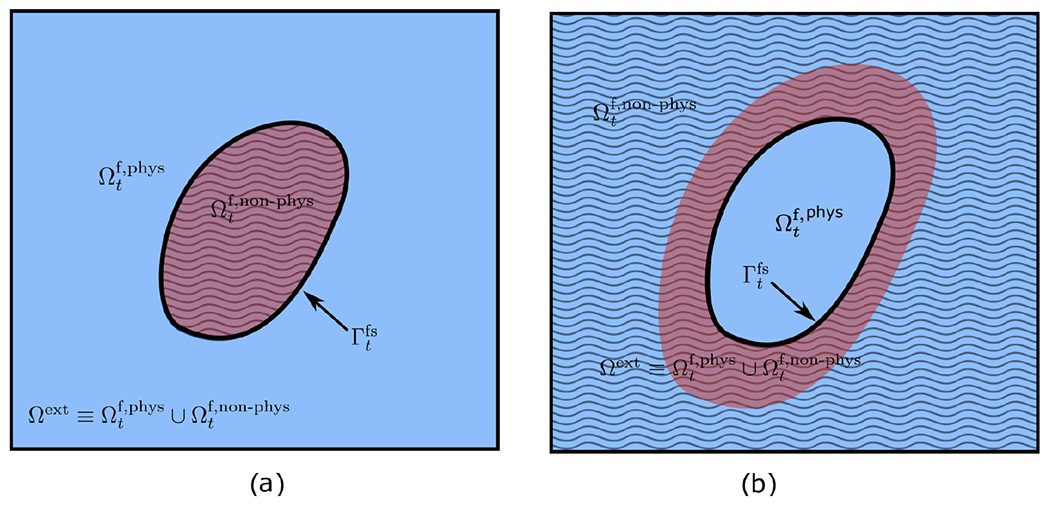
In the immersed Lagrangian-Eulerian method, the incompressible Navier-Stokes equations are solved on an extended computational domain that incorporates both fluid and solid subregions, and is split into a physical and a nonphysical fluid regions. (a) In this configuration a simply connected domain represents the volumetric structure that is immersed in the fluid. The non-physical fluid region in this case is the region occupied by the solid and shown by wavy stripes. (b) In this case, the physical fluid region is enclosed by the thick shell-like structure of the solid. The non-physical domain (shown by wavy stripes) includes the solid domain in addition to an extended region to obtain a fixed Cartesian computational domain.
The kinematic constraint, which requires that the fluid and solid move together along the fluid-structure interface, is imposed through an interfacial force density applied along . This singular force density implies a discontinuity or jump in the traction associated with the extended fluid stress along . We denote a jump in a scalar field at position along the interface as , in which and are respectively the limiting values approaching the interface position from the physical fluid region and the non-physical fluid region in the normal direction. The resulting ILE formulation is
| (10) |
| (11) |
| (12) |
| (13) |
| (14) |
| (15) |
| (16) |
in which is an interfacial surface force density that is the Lagrange multiplier for the kinematic condition in Eq. (15). Eq. (12) describes discontinuities in the extended fluid pressure and viscous stress that are related to the normal and tangential components of the interfacial Lagrange multiplier force, respectively.
Additionally, the right hand side of Eq. (16) is the exterior fluid traction in current coordinates
| (17) |
This equation accounts for the dynamic interface condition, which is the “Neumann part” of our Dirichlet-Neumann coupling approach, in which the exterior fluid traction forces are imposed as boundary conditions to the solid domain. Note that this equation also implies that only the physical fluid stresses from within are able to drive the dynamics of the structure.
2.2.1. The penalty ILE formulation
We first describe our penalty ILE formulation for a solid structure fully immersed in a fluid domain. Exactly imposing the kinematic constraint, Eq. (6), in the formulation detailed in Sec. 2.2 requires solving a saddle-point system that couples the Eulerian and Lagrangian variables. As in our earlier work on rigid-body FSI [12], we develop a numerical method that avoids the need to solve such systems by relaxing the kinematic constraint. We do so by introducing two representations of the fluid-structure interface and applying forces that act to penalize displacements between the two representations. This penalty method thereby determines an approximate Lagrange multiplier force instead of solving for the exact Lagrange multiplier to impose the kinematic matching condition. Specifically, along with the mapping that determines the kinematics of the structure, we introduce an explicit representation of the fluid-structure interface that is parameterized by the deformation mapping and that moves with the fluid, so that ; see Fig. 3(c).
Figure 3:
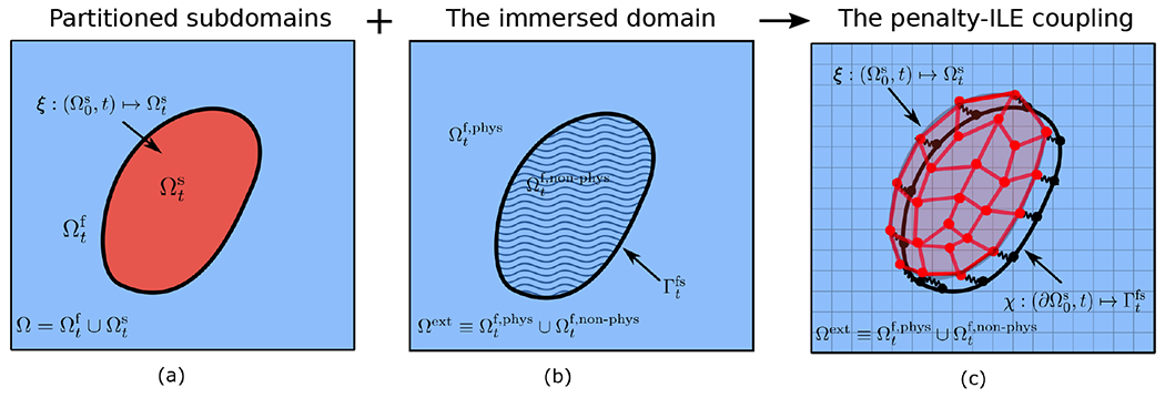
Aspects of (a) partitioned and (b) immersed FSI formulations are integrated in the (c) penalty-ILE coupling. The fluid-structure interface representation (determined by ) conforms to the boundary of the structure (determined by ) in an approximate sense. The discrepancy between the two representations is exaggerated here for illustration purposes. In practice, we ensure that this maximum displacement is no greater than 0.1 of the Cartesian grid spacing. The local fluid velocity determines the motion of the surface representation , whereas the no-slip condition is satisfied in an approximate sense by spring-like forces that penalize displacements between the two representations of the fluid-structure interface.
The approximate Lagrange multiplier force is determined by linear spring and dampers,
| (18) |
in which is a tethering penalty parameter and is a damping penalty parameter. This force penalizes deviations from the constraint and, in the discretized equations, acts to ensure that the two interface representations are at least approximately conformal in their motion. It is possible to control the discrepancy between the two configurations, and as , the formulation exactly imposes the constraint that the two interface representations move together. Although kinematic constraints can be imposed through spring forces alone, we have found that including a small amount of damping can reduce spurious numerical oscillations. We demonstrate in Sec. 4.1 that including damping can reduce the value of required to achieve a given displacement tolerance, which, in turn, can allow for larger time step sizes.
Additionally, note that in the penalty ILE formulation the incompressibility of the fluid is discretely imposed through the solution of the Navier-Stokes equations. Therefore, for consistency, a structure that is fully immersed in fluid must also be incompressible in the present formulation. Exactly imposing this constraint in a Lagrangian framework is challenging. To simplify the implementation, we relax this condition and use a nearly incompressible structural model that is characterized by a Poisson’s ratio approaching 0.5 and a corresponding bulk modulus approaching infinity. This implies that . Our numerical tests demonstrate that the resulting volume conservation is superior to an immersed finite element-finite difference scheme that treats the structure as exactly incompressible [23].
2.2.2. The penalty ILE formulation for fully compressible solid structures
It is straightforward to use our penalty ILE formulation to model fully compressible solid structures so long as the structure is not fully immersed in fluid (i.e., part of the solid boundary is not in contact with the fluid). We enforce the kinematic constraint through the same penalty strategy as in the incompressible model, except in this case, the additional representation of the fluid-structure interface is only a subset of the total solid boundary; see Fig. 4. Because part of the solid boundary does not contact the physical fluid subregion, the incompressibility of the extended fluid region does not constrain the volume of the structure. An example of such a model is flow through an enclosed tube or a reservoir for which the FSI coupling is enabled only at the inner surface of the tube while the outer side is handled through suitable boundary conditions for the structural model.
Figure 4:
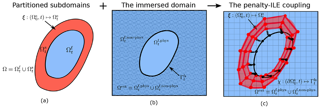
The coupling for the compressible structure combines (a) the partitioned formulation and (b) immersed FSI formulations to create (c) the penalty-ILE coupling. The fluid-structure interface representation in this case (determined by ) conforms to the inner boundary of the structure (determined by ) in an approximate sense. The displacement between the two representations is exaggerated here for illustration purposes.
2.3. The structural mechanics formulation
We use a standard Galerkin finite element approach to model the structural deformation. Such methods rely on a weak form of the equations of elastodynamics. Briefly, by assuming that the immersed solid structure has uniform density and integrating Eq. (4) for all smooth test functions and , we obtain
| (19) |
(We remark that it is straightforward to consider nonuniform density structural models.) Integrating by parts yields
| (20) |
Note that the second term on the right-hand-side of Eq. (20) also appears in the force balance equation, Eq. (7), and can be replaced by exterior fluid traction forces as
| (21) |
Notice that in the surface integral in Eq. (21), we use to obtain the fluid traction forces per unit reference area. We directly discretize this equation in our numerical scheme.
In this paper, we use hyperelastic structural models, for which the first Piola-Kirchoff stress tensor is related to the strain energy functional as in Eq. (8), and we use a nearly incompressible structural formulation as a penalty method for the exactly incompressible case. For nearly incompressible large-deformation elasticity, we relax the incompressibility constraint by re-expressing in Eq. (8) via and assuming an additive splitting of the elastic energies associated with volume changing and volume preserving motions. This splitting is motivated by the assumption that a uniform pressure should produce changes in size but not in shape [69, 70]. We first write for an isotropic material as a function of the scalar invariants in which
| (22) |
| (23) |
| (24) |
with being the right Cauchy-Green deformation tensor. To achieve the desired split satisfying material frame invariance, we use a standard approach based on the Flory decomposition [71] to reformulate the strain energy with the modified strain invariants, through multiplicatively decomposing into dilatational and deviatoric parts, . This also results in a modified right Cauchy-Green strain tensor, . Similarly, the first modified invariant of is . The specific model used in this work is of the form
| (25) |
in which characterizes the response of the material to shearing deformation in terms of the first modified invariant, and is a volumetric energy that penalizes compression or expansion. It is preferred for to satisfy . Unless otherwise noted, we use a neo-Hookean material model for the elastic structure,
| (26) |
Taking the derivative with respect to the deformation gradient tensor yields
| (27) |
in which and are the deviatoric and dilatational stresses, respectively. Using Eq. (26), these stresses are,
| (28) |
| (29) |
in which and are the shear and bulk moduli, which are related by the Poisson’s ratio via . The above stress formulation can be easily extended to other isotropic and anisotropic constitutive laws. In fact, the present ILE formulation is not restricted to neo-Hookean material models, and alternative hyperelastic or even inelastic material models can be readily used.
3. Numerical discretization
We use a standard -conforming Lagrangian finite element method to discretize the elastodynamics equations and a finite difference method to discretize the Navier-Stokes equations. Further details of the discretization for each sub-problem are given below.
3.1. Structural discretization
Let be a triangulation of , the reference configuration of a three-dimensional solid structure, with nodes. Let
| (30) |
be the standard interpolatory nodal basis functions in which each is nonzero at exactly one node of the triangulation. We let and be the coordinates of the triangulation’s nodes in the reference and current configurations, respectively. A continuous description of the configuration of the structure is defined by
| (31) |
Using the same FE basis functions, the deformation gradient is approximated as
| (32) |
This FE approximation to the deformation gradient tensor is used to compute the approximation to the first Piola-Kirchhoff stress tensor along with critical geometrical quantities.
Similarly, we construct the fluid-structure interface configuration described by the mapping by extracting the portion of the surface of the solid mesh that interacts with the fluid. Let be the number of nodes on the surface of the triangulation and let
| (33) |
be the subset of , the volumetric finite element space, which is nonzero on . Hence we define the configuration of the surface as
| (34) |
For each shape function in , the standard Galerkin approach for the structural subproblem based on Eq. (21) leads to the following evolution equation for the displacement of a single node:
| (35) |
in which is a nonlinear function of through the constitutive relation as a function of the deformation gradient. In our numerical scheme, we also compute the projection of the normal and tangential components of the surface force in Eq. (18) per unit current area, , along the Lagrangian surface mesh. This is needed to specify the conditions for the pressure and the viscous stress and calculate the resulting exterior fluid traction . Eq. (35) corresponds to a system of linear equations for the nodal accelerations, which we write as
| (36) |
in which is the mass matrix with entries , and is the applied load vector, which here includes the exterior fluid traction supported on fluid-structure interface and the internal force density supported on the interior of the structure. Gaussian quadrature rules are used to approximate the integrals. We use selective reduced integration [72] to avoid volumetric locking for nearly incompressible structural models.
3.2. Fluid discretization
We discretize the incompressible Navier-Stokes equations using a finite difference approximation on an adaptively refined marker-and-cell (MAC) staggered Cartesian grid [73, 74]. An unsplit, linearly-implicit discretization of the incompressible Navier-Stokes equations that solves time-dependent incompressible Stokes equations with the projection method used only as a preconditioner for the flexible generalized minimal residual method (FGMRES) solver applied to the Stokes operator. This allows for imposing physical boundary conditions along the boundaries of the Eulerian computational domain using methods detailed previously [73, 74]. The divergence, gradient, and Laplace operators are discretized using compact second-order accurate differencing schemes. The nonlinear advection terms in the Eulerian momentum equation are treated by a staggered-grid variant of the piecewise parabolic method (PPM) [73–75].
3.3. Fluid-structure coupling
We leverage a coupling scheme based on the immersed interface method for discrete surfaces [53] that accounts for the physical jump conditions in the extended fluid stress along the fluid-solid interface and allows for the accurate evaluation of the exterior fluid traction. To impose the jump in the stress, we first construct a continuous representation to the jump conditions in Eq. (12) obtained by the projection along the surface mesh using the space defined by Eq. (33). Geometrical quantities, including the surface normals and surface Jacobian determinant, that are needed by the IIM discretization are obtained by directly differentiating the discrete representation [12, 53]. Briefly, given a scalar function , its projection onto the subspace is defined by requiring to satisfy
| (37) |
Because the projection is defined via integration, the function does not need to be continuous or even to have well-defined nodal values. By construction, however, will inherit any smoothness provided by the subspace . In particular, for -conforming Lagrangian basis functions, will be at least continuous. To solve for the projected jump conditions, linear systems of equations involving the boundary mass matrix need to be solved, in which has components . The integral in Eq. (37) is evaluated using seventh-order Gaussian quadrature. Notice that these projections are computed only along the fluid-solid interface and involve only surface degrees of freedom. Consequently, the computational cost of evaluating these projections is asymptotically smaller than the solution of either the fluid or structure sub-problem. Furthermore, this process can be repeated for each component of a vector-valued function independently.
To interpolate the discretized Eulerian velocity field to the Lagrangian surface mesh, we use a corrected trilinear (or, in two spatial dimensions, bilinear) interpolation scheme that accounts for the known discontinuities of at intersection points with Cartesian finite difference stencils. The interpolated velocity field at intersection points is then projected onto the space spanned by the nodal basis functions using Gaussian quadrature. A surface-restricted projection is also used to obtain nodal values of the exterior fluid traction in Eq. (35), including the exterior fluid pressure and exterior viscous shear stress, see Kolahdouz et al. [12, 53] for more details of these calculations.
In the Eulerian discretization, we account for the jump conditions in the pressure and the first normal derivatives of the velocity along the fluid-structure interface that occur in the ILE formulation by modifying the definitions of the pressure gradient and the viscous terms for those finite-difference stencils that cross the immersed interface using generalized Taylor series expansions; implementation details are discussed in prior work [12, 53].
3.4. Time integration
We define a vector that includes all of the Eulerian and Lagrangian quantities that need to be updated as . We denote by and the time steps associated with the fluid and solid mechanics solvers respectively, for which we assume with an integer value of . Starting from time step at time to time step at time , we use the second-order Strang splitting scheme [76], in which within three steps we: 1) update the structure by solving the elastodynamic equations advancing over steps, each time solving with the time step and treating the fluid traction that loads the structure along as fixed in time; 2) solve the IIM/FSI subproblem over a full time step , treating the structural configuration as constant in time; and 3) solve the elastodynamic equations over another steps each with the time step , treating the fluid traction as fixed in time. As described above, in this multirate (MR) approach, for each half-time advancement of the structural solution in steps 1 and 3, the time integration of the elastodynamics solver can be subdivided into sub-steps. This capability is particularly appealing for problems in which the stiffness of the structural model requires structural time step sizes that are substantially smaller than the time steps required to resolve the fluid dynamics. We remark that unless otherwise mentioned, we set for results presented in Sec. 4.
3.4.1. Time integration of the elastodynamics equations
The solution approach for a structural time step is detailed here. Denote by the action of the elastodynamics solver over the time increment that acts on a solution vector . This solution vector includes all of the Eulerian and Lagrangian variables, but only advances the volumetric structural variables and while keeping the remaining variables fixed. The discretized equation, Eq. (35), is solved over the time increment to obtain using a modified trapezoidal scheme. Defining , the time-integration is performed in two steps. In the first step, we use a modified Euler method and obtain predicted values
| (38) |
| (39) |
Using and , we calculate (recall includes the terms on the right-hand-side of Eq. (35)). In the second (corrector) step, we use a modified (explicit) trapezoidal rule, so that
| (40) |
| (41) |
Note that in practice, we never directly evaluate , but instead approximately evaluate its action via a Krylov solver. In particular, we use the symmetric iterative solver MINRES, given the positive definiteness of the mass matrix.
3.4.2. IIM time integration scheme
Denote by the action of the IIM solver over a full time step that acts on the solution vector that includes all of the Eulerian and Lagrangian variables but only advances , and . Starting from and at time and at time , we compute , and . Briefly, using the discrete velocity restriction operator , we first obtain initial approximations to the interface position at time via
| (42) |
Next, we solve for , and in Eqs. (10)–(15) via
| (43) |
| (44) |
| (45) |
in which is obtained from a high-order upwind spatial discretization of the nonlinear convective term [73]. In Eq. (43), is the force-spreading operator at the half time step configuration and is the discrete Eulerian body force on the Cartesian grid that corresponds to the sum of all the correction terms due to physical jump conditions computed using the Lagrangian force . In Eq. (45), is the velocity restriction operator at the half time step configuration. , and . respectively represent discrete gradient, Laplacian, and divergence operators. This time stepping scheme requires only linear solvers for the time-dependent incompressible Stokes equations. We solve this system of equations by the FGMRES algorithm with a preconditioner based on the projection method that uses inexact subsolvers for the velocity and pressure [73]. In the initial time step, a two-step predictor-corrector method is used to determine the velocity, deformation, and pressure; see Griffith and Luo [23] for further details.
3.4.3. Fluid-structure interaction time stepping scheme
A loosely coupled scheme is considered for the time integration of the equations. For the solution vector over a fluid time step using the Strang splitting scheme we have,
| (46) |
With this time-staggered approach, the overall algorithm to solve the fluid-structure problem is
Step I: Solve the elastodynamic equation Eq. (36) over a half time step using the modified trapezoidal scheme in Eqs. (42)–(45) to advance from step to and obtain . If multi-rate time-stepping capability is used, the elastodynamic equation is solved with over a loop of size with number of steps.
Step II: Calculate the penalty force using the most recent position of the volumetric structural mesh and the surface mesh that moves with the fluid.
Step III: Solve for the IIM subsystem in Eqs. (10)–(15) over a full time step and obtain the updated Eulerian velocity field and pressure as well as the Lagrangian velocity and positions of the surface mesh and the exterior fluid traction forces .
Step IV: Using the exterior fluid traction force from Step III, solve the elastodynamic equation Eq. (36) over a half time step using the modified trapezoidal scheme in Eqs. (42)–(45) to advance from step to and obtain . If multi-rate time-stepping capability is used, the elastodynamic equation is solved with over a loop of size with number of steps.
Our numerical experiments indicate that we can find values of that are small enough so that the scheme is stable, as was also suggested in a recent analysis by Hua and Peskin [77] for the standard immersed boundary method that uses the same form of approximate Lagrange multiplier force. Additionally, notice that the ILE formulation easily allows for taking smaller solid time-step in the explicit finite element solid mechanics solver. This will be an important feature for problems that pose larger stiffness in the solid domain than the fluid and is achieved through increasing the parameter without changing the overall fluid time-step or penalty parameters.
3.5. Software implementation
The ILE approach has been implemented in the open-source IBAMR software [78], a C++ framework for FSI modeling using immersed formulations. IBAMR provides support for large-scale simulations through the use of distributed-memory parallelism and adaptive mesh refinement (AMR). IBAMR relies on other open-source software libraries, including SAMRAI [79, 80], PETSc [81], hypre [82, 83], and libMesh [84]. For example, mesh handling tools in libMesh allows for the use of separate data structures for the volumetric and the corresponding surface structural meshes throughout the entire computation by storing the so-called interior parent elements. All the capabilities of the present approach and benchmark examples are included in the IBAMR software framework, version 0.11.0 or newer.
4. Numerical results
We use structural elements in our computational tests (bilinear elements in two spatial dimensions and trilinear elements in three spatial dimensions). The grid spacing on the finest level of the hierarchical, locally refined Cartesian grid is , in which is the coarsest level grid spacing, is the refinement ratio, and is the number of refinement levels. Unless otherwise noted, the initial ratio of the Lagrangian element size of the structural meshes to the Eulerian grid spacing, denoted by , is approximately along the fluid-structure interface. In all computations, we require that the maximum absolute displacement between the two representations of the fluid-structure interface is no greater than 0.1 of the Eulerian meshwidth. Note that to achieve , the spring penalty parameter needs to satisfy . Additionally, we take the damping parameter to satisfy . Under grid refinement, we expect that the penalty force will converge to the physical loading forces and satisfy . In particular, for our convergence tests, we maintain to keep the advective Courant-Friedrichs-Lewy (CFL) number fixed under grid refinement. It is then convenient to choose and also optionally choose is determined by, first, choosing the finest grid spacing to be considered, say , along with the corresponding time step size . We then empirically determine approximately the largest value of that allows the scheme to remain stable with and . We then use the prescribed relationship between and to determine (and η) for all coarser cases. This ensures that the numerical parameters are stable for all grid spacings considered in the convergence test while using scalings that ensure that the method achieves its targeted convergence rate. Note that in our explicit time stepping approach to coupling the fluid and solid degrees of freedom, we expect a largest stable value of spring penalty parameter for fixed spatial and temporal discretization parameters. In a given problem, if there is already a physical estimate for the total fluid forces acting on the fluid-structure interface, this estimate along with a targeted discrepancy tolerance , can help with an initial guess for the spring stiffness, e.g., via . Regardless of whether a reasonable estimate is available however, in practice we find the approximation for the close to the stability limit by tuning the parameter using the method of bisection. Damping appears to be optional, and a slight amount of damping can be added while finalizing the tuning of . All computations use a tight relative convergence threshold of for all iterative linear solvers. To avoid volumetric locking in incompressible cases, we use selective reduced integration [72], in which third-order Gaussian quadrature is used to integrate the deviatoric stress and first-order Gaussian quadrature is used for the dilatational stress . For simplicity in the rest of the paper we drop the superscript “f” from the fluid time step and use the general notation and , unless otherwise mentioned. Tests include two dimensional cases in Secs. 4.1, 4.2 and 4.3 and three dimensional cases in Secs. 4.4 and 4.5.
4.1. Soft disk in a lid driven cavity 1
This benchmark test involves a soft structure in a lid-driven cavity flow. Slightly different versions of this example have been adapted in previous studies [23, 85, 86]. The computational domain is , a square of size . The immersed structure is initially a disk of radius , centered at . A uniform velocity is imposed along the top boundary and zero-velocity conditions are imposed at all other boundaries. The fluid has a uniform density and dynamic viscosity . The soft structure has a shear modulus and Poisson’s ratio . The density ratio is set to . We consider the time span , during which the disk goes through slightly more than one rotation inside the cavity. The Eulerian domain is discretized using a refinement ratio of with Cartesian grid levels with a grid spacing of on the coarsest level and on the finest level. The time step size is , and the force penalty parameters are set to and . Unless otherwise noted, these forms of penalty parameters are used for all the following tests related to the soft disk in a lid driven cavity.
Fig. 5 shows the snapshots and the corresponding velocity fields at six different times. The mesh deformation of the volumetric solid structure is plotted along with the surface representation (colored in pink), which clearly shows that the two are conformal in their motion. Additionally, notice that the induced flow by the driven lid brings the structure into near contact with the upper boundary of the domain. Starting from approximately time in Fig. 5(c) to Fig. 5(e), the entrained structure undergoes very large deformation in a near-contact condition with the domain’s boundary. Fig. 5(d) shows how the near-contact dynamics are captured using the ILE algorithm.
Figure 5:
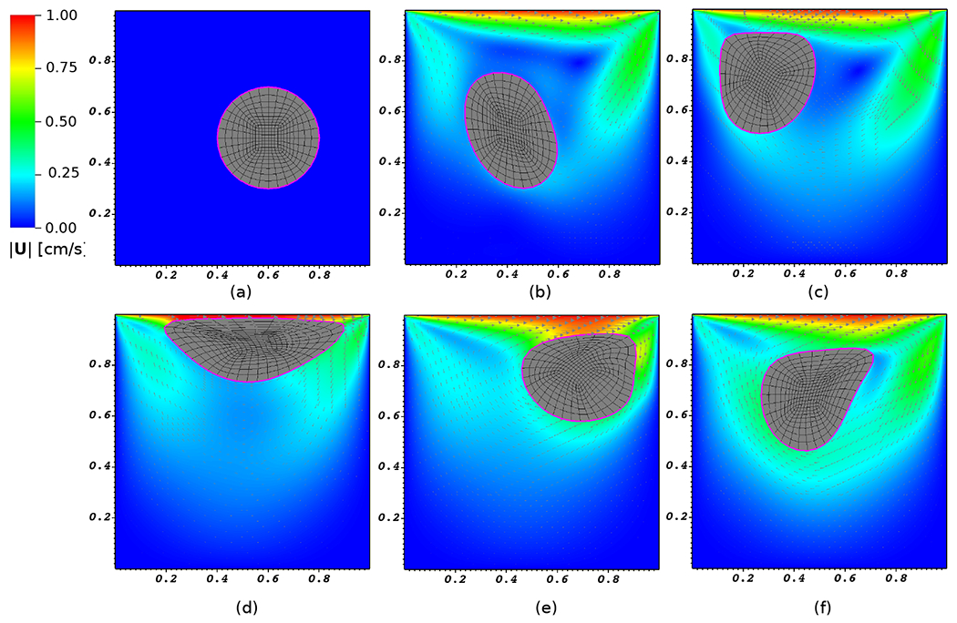
The computed velocity field and motion of the soft disk in a lid driven cavity at times (a) , (b) , (c) , (d) , (e) , and (f) .
To investigate how our use of a nearly incompressible structural formulation as a penalty method for the exactly incompressible case affects volume conservation, we consider two additional Poisson’s ratios and 0.4999. Fig. 6 shows the trajectory of the centroid of the soft disk along with the percentage of volume change over time. For comparison of the volume conservation, we compare against a solution based on the immersed finite element/difference method reported by Griffith and Luo [23] using a three-point regularized delta function kernel and the same time step size and grid spacing as the ILE cases. Notice in Fig. 6(a) that there is an excellent agreement between the trajectories of the case with and , whereas slight differences are observed for the case with . However, as depicted in Fig. 6(b), even for , the ILE formulation yields substantially improved volume conservation compared to the immersed finite element/difference method, generating volume conversation errors that are at least two orders of magnitude smaller. Volume conservation further improves as . Given these observations, it appears that a choice of is a good compromise for our FSI simulations considering both the convergence of the centroid’s trajectory, overall volume conservation, and time step size restrictions associated with increased bulk moduli. (Because we use a fully explicit time stepping scheme for the structural dynamics, as .)
Figure 6:
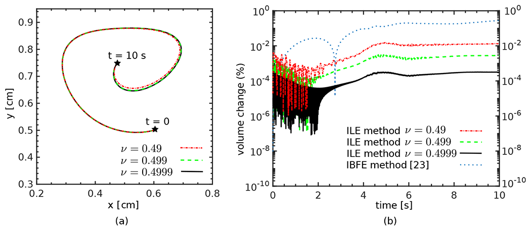
(a) Trajectory of the centroid of the soft disk over time for three different values of the Poisson’s ratio . (b) The percentage of volume change over time for three values of the Poisson’s ratio along with the percentage of volume change using the immersed finite element/difference method [23].
As a further verification, a mesh refinement study using a series of three grid resolutions is conducted. The grid refinement is performed by changing the number of AMR levels. The case considered thus far, with , is used as an intermediate resolution, along with locally refined grids with , and 4 levels. The Lagrangian meshes are consistently refined (or, for case, coarsened) with the Eulerian grid to maintain . The same grid-dependent time step size and penalty parameters are used as detailed above. Fig. 7(a) shows the trajectories of the centroid of the soft disk for all the four grid sizes. The trajectory clearly converges under grid refinement. Further, for the choice of penalty parameters used here, we expect pointwise second-order convergence for the discrepancy between the positions of the two interface representations. Fig. 7 (b) shows , at the final time . Second-order convergence in the maximum norm is apparent. Fig. 7 (c) further details the change of the norm of the discrepancy over time,
Figure 7:

(a) The trajectory of the soft disk’s centroid for a series of grid resolutions. (b) Norm of the discrepancy in the fluid-structure interface configurations at the final time . (c) Time history of the difference between the positions of the two representations of the fluid-structure interface over time.
In addition to the pointwise Lagrangian displacement, we have computed empirical convergence rates for the structural volume of the soft disk over the entire course of the simulation. Because there is no exact solution available for the full dynamics of this problem, we use a Richardson extrapolation procedure to estimate the convergence rate in the norm of the error in the soft disk’s centroid ,
| (47) |
in which and are defined as
| (48) |
| (49) |
The convergence rates of the centroid of the soft disk along with the volume of the disk are reported in Fig. 8(a), clearly showing second-order convergence in volume conservation and between first and second-order convergence for the centroid’s position. To further examine the contribution to the displacement error due to the time-integration algorithms in the FSI system, we analyze the temporal convergence of the disk’s centroid at the final time . The grid-spacing is fixed in this case, corresponding to refinement levels. We use the solution from a very small time-step of as the reference solution. As shown in Fig. 8(b), full second-order convergence is evident. This indicates that the reduction in the accuracy of the disk’s centroid in Fig. 8(a) can be attributed to the spatial discretization error and not the temporal part.
Figure 8:
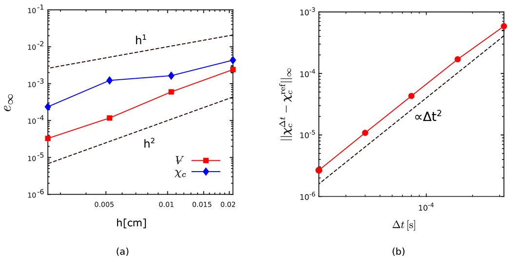
(a) The spatio-temporal convergence rates of the volume and centroid of the soft disk in the lid driven cavity test case over the time interval . (b) The temporal convergence of the disk’s centroid for a fixed grid with at . Second-order convergence is apparent.
As our last investigation for the soft disk moving in a lid driven cavity, we study the sensitivity and stability of our simulations for the choice of and the impact of damping. Once again, we consider the case with grid levels, , and the same time step size as before to study the sensitivity of the numerical algorithm to penalty parameters based on changes in the spatio-temporal discretization. Fig. 9(a) examines the sensitivity of the numerical algorithm to damping and its influence on the accuracy of the computed solution by varying and to obtain a table demarcating cells with stable vs. unstable behavior. The numbers reported for cells with stable pairs is the maximum discrepancy between the two Lagrangian representations at time , shown as a factor of . Stable results are obtained for , without using any damping. The narrower range includes results with an acceptable accuracy based on the maximum tolerance, i.e. . On the other hand, choosing can reduce the displacement error and broaden the range of effective value. Additionally, using a very large damping parameter leads to instability, regardless of the choice for . Green-colored cells are the ones that satisfy the condition . Yellow cells are stable cases with a maximum discrepancy larger than . Fig. 9(b) shows the maximum discrepancy between the two Lagrangian representations over time for three acceptable cases (maximum discrepancy equal or smaller than ) from the table with a fixed and different choices of . Non-zero damping values are shown to further reduce spurious numerical oscillations. Finally, Fig. 10(a) and Fig. 10(b) assess the sensitivity of the result to stable choices of , the centroid’s trajectory and the deformation at for three distinctive and selected choices of . Results obtained for different choices of penalty parameters appear to be virtually identical and are largely insensitive to the values of and within the acceptable region, i.e., the region with the maximum discrepancy equal or smaller than .
Figure 9:
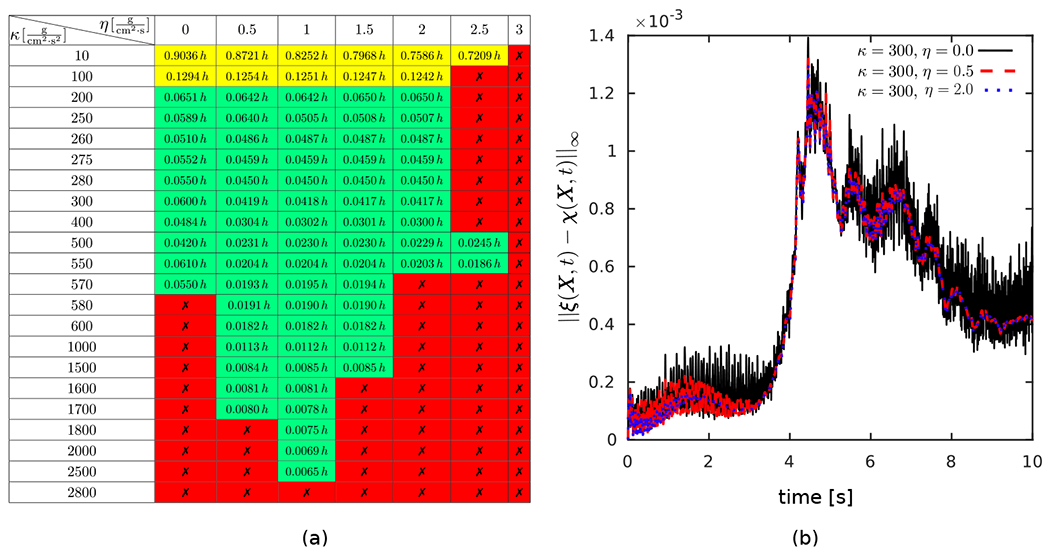
(a) A table of stable vs. unstable penalty pairs with red color cells marked by symbol showing unstable cases. The numbers reported for stable pairs is the maximum discrepancy between the two Lagrangian representations at , shown as a factor of Green cells are the acceptable cells with the additional condition of imposed in our simulations. Yellow cells show stable cases with maximum discrepancy larger than A non-zero damping parameter does not seem to be required to achieve a stable result with an acceptable maximum discrepancy. Additionally, note that there can always be a small enough time-step for which the currently unstable pairs would become stable. (b) The maximum discrepancy between the two Lagrangian representations over time for 3 cases from the table with fixed and different choices of . Although the oscillations are all smaller than , a small amount of non-zero damping is shown to further reduce spurious numerical oscillations.
Figure 10:
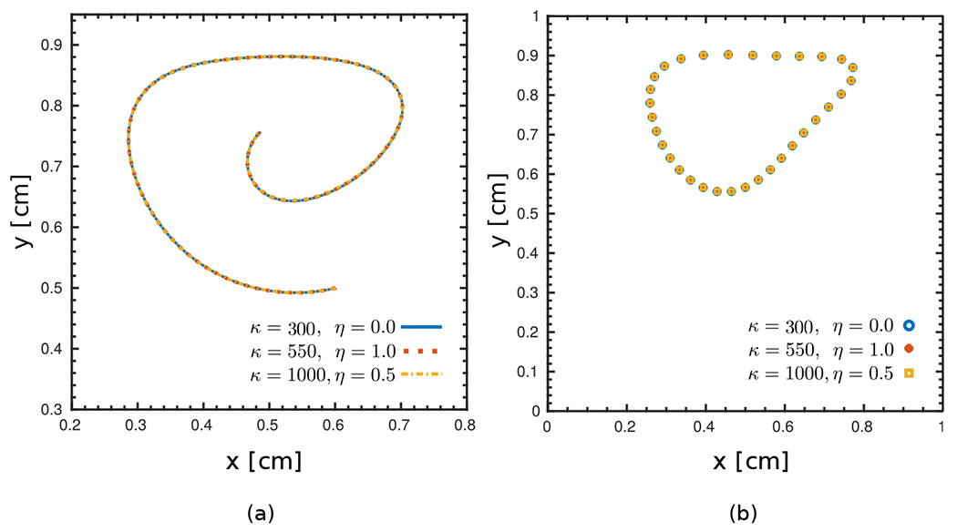
(a) The trajectory of the centroid of the soft disk for three selected pairs of within the stable cells in Fig. 9(b), including a case with . (b) Nodal positions of the surface of the structure for the same pairs of at . The results are largely insensitive to the values of penalty parameter values considered here.
4.2. Modified Turek-Hron benchmark 2
This test was originally proposed by Turek and Hron [62] for benchmarking fluid-structure interaction algorithms. We examine the performance of our methodology for models with large added effects and large deformation resulting from the presence of a light structure. The structure is composed of a stationary circular disk of radius centered at and an elastic tail that has a length of and thickness , see the schematic in Fig. 11. The rectangular domain surrounding the structure has a height and length extending over . A horizontal parabolic velocity profile of is imposed upstream of the structure in which is the mean velocity. Zero normal traction and zero tangential velocity are imposed at the outlet . Zero velocity conditions are imposed at and . The Eulerian domain is discretized using a refinement ratio of with Cartesian grid levels with a grid spacing of on the coarsest level. Note that given the dimensions of the computational domain and the center position of the circular disk as in the original study, the immersed body is positioned asymmetrically in the -direction. The circular disk is described by a nearly rigid material. The left end of the tail is fixed and attached to the cylinder. We consider two cases with different density ratios, shear moduli, and mean entrance velocities. The associated parameter sets including physical properties of both fluid and solid are reported in Table 1. In the original specification, a compressible St. Venant-Kirchhoff model was used to describe the elastic tail with Poisson’s ratio , but in this example we instead consider a nearly incompressible neo-Hookean material with Poisson’s ratio . The time step size is , and the force penalty parameters are set to and with for case 1 and for case 2 described in Table 1. Table 2 compares the -displacement of point A and the Strouhal number (St) to previous studies [62, 87–90] for the two cases reported in the original work by Turek & Hron. The Strouhal number is St , in which is the oscillation frequency for the -displacement of point and is the diameter of the circular disk. We observe good agreement between values produced by the present method and previous work, reflected also in the periodic vertical and horizontal positions of point at the tip of the tail. Note that the study by Lee and Griffith [88] uses an exactly incompressible material for the beam. Fig. 12 shows the dynamics of the beam and its deformation in the interaction with surrounding fluid with density ratio and the Reynolds number . Vorticity magnitudes and pressure contours are respectively shown in panels (a)–(b) and (c)–(d) for times after self induced periodic oscillations have developed in the structure and flow. Both vorticity and pressure contours indicate the periodic behavior downstream of the flow.
Figure 11:

Schematic of the modified Turek-Hron benchmark including the geometry and boundary conditions.
Table 1:
Parameters for the modified Turek-Hron benchmark (Sec. 4.2).
Table 2:
Comparison of computational values for the modified Turek-Hron benchmark for case 1 & 2 described in Table 1. Other simulation parameters include , and .
Figure 12:
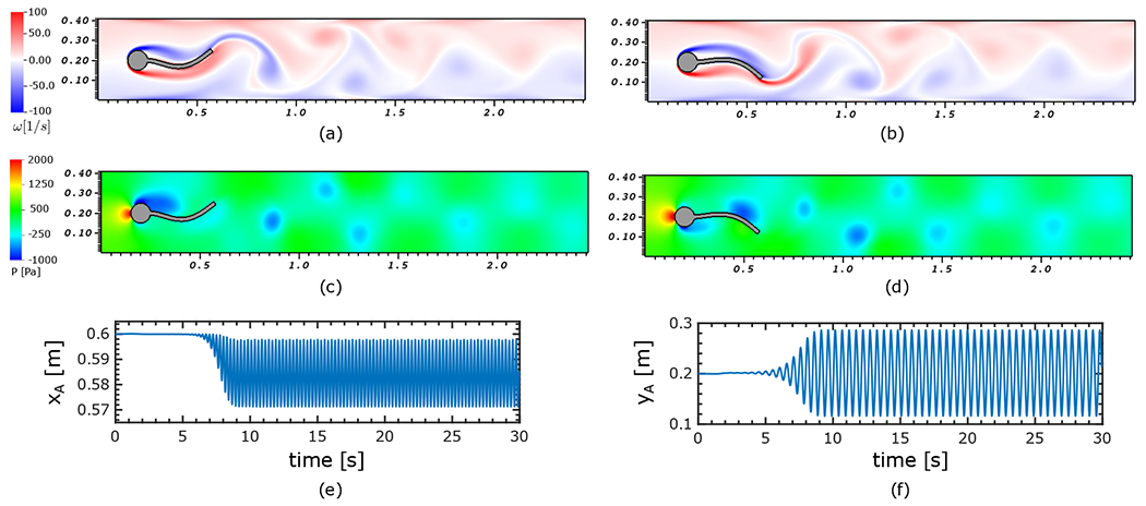
Dynamics of modified Turek-Hron benchmark corresponding to case 1 (FSI2 in [62]) (a) vorticity field at , (b) vorticity field at , (c) pressure field at , (d) pressure field at , (e) time history of horizontal displacement of point at the tail and (f) vertical displacement of point at the tail.
As an additional verification test, we have explored the sensitivity of our results in the limit of the Poisson’s ratio approaching . Similar to the soft disk example in Sec. 4.1, we choose two additional Poisson’s ratios, and along with the default and study the tip of the tail’s position (point A in Fig. 11) over time. For the case of , we maintain stability for the overall scheme by using a smaller , which is achieved by taking . Notice that the fluid time step size does not need to be reduced to accommodate this increase in the bulk modulus. As shown in Fig. 13, there is very little difference between all the three cases and in particular, there is an excellent agreement between the tip’s position for and .
Figure 13:
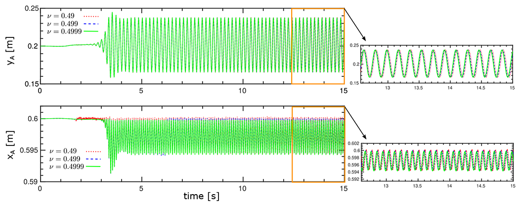
Time histories of the vertical (top) and horizontal (bottom) displacements of the flexible tail in the modified Turek-Hron benchmark (case 2) for three different values of the Poisson’s ratio approaching the fully incompressible limit .
Next, we perform a grid refinement study for case 2 in Table 1. In our AMR framework, we vary the number of refinement levels by taking two additional grid spacings with levels and along with the default . We use the same time step size and penalty parameters as before and examine the vertical and horizontal position of the tip of the tail (point A in Fig. 11). Figs. 14(a) and (b) show the vertical and horizontal position of point over time, respectively. There is a good agreement across all grid spacings for the magnitudes of both vertical and horizontal variations. Additionally, there is a much smaller phase lag between the positions for and than the case with . The same trend is also apparent in the convergence of the trajectory of point A under grid refinement, as shown in Fig. 14(c).
Figure 14:
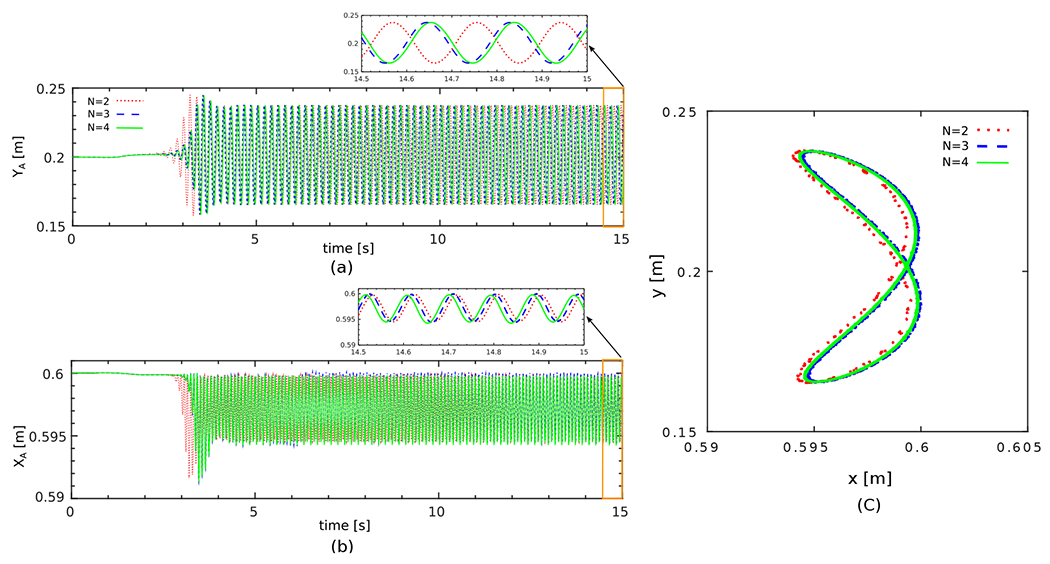
(a) Time histories of the vertical and (b) horizontal displacements of point A at the flexible tail in the modified Turek-Hron benchmark (case 2) under grid refinement. (c) The trajectory of point A at the flexible tail under grid refinement for multiple cycles.
Finally, we study the effect of changes in the fluid dynamics parameters and solid structure properties on the vertical oscillation amplitude of point at the flexible tail. To study the fluid dynamics parameters, we fix the solid properties based on case 2 in Table 1 and vary the fluid viscosity and inlet mean velocity . Fig. 15(a) shows the vertical amplitude as circles with different diameters. The amplitude of associated with case 2 of Table 2 (shown as a red circle) is used as a reference size for comparison. Clearly, as we increase the viscosity the vertical amplitude decreases. Similarly, Fig. 15(b) indicates the vertical amplitudes of point at the tail for a range of shear modulus and solid density of the solid structure. This time, fluid dynamics properties are fixed corresponding to the reference point of case 2 in Table 2. Increasing the shear modulus tends to damp the vertical amplitude of the periodic oscillation of the tail while larger density ratios result in larger vertical amplitude. The pairs shown by “✕” correspond to cases for which no apparent periodical oscillations are observed. Regarding the influence of material properties on penalty parameters, our numerical experiments show that the penalty parameters are largely insensitive to changes in the shear modulus. Additionally, we noticed weak dependencies on the density ratio, fluid viscosity, and the mean inlet flow that are readily resolved by slightly adjusting the penalty parameters.
Figure 15:
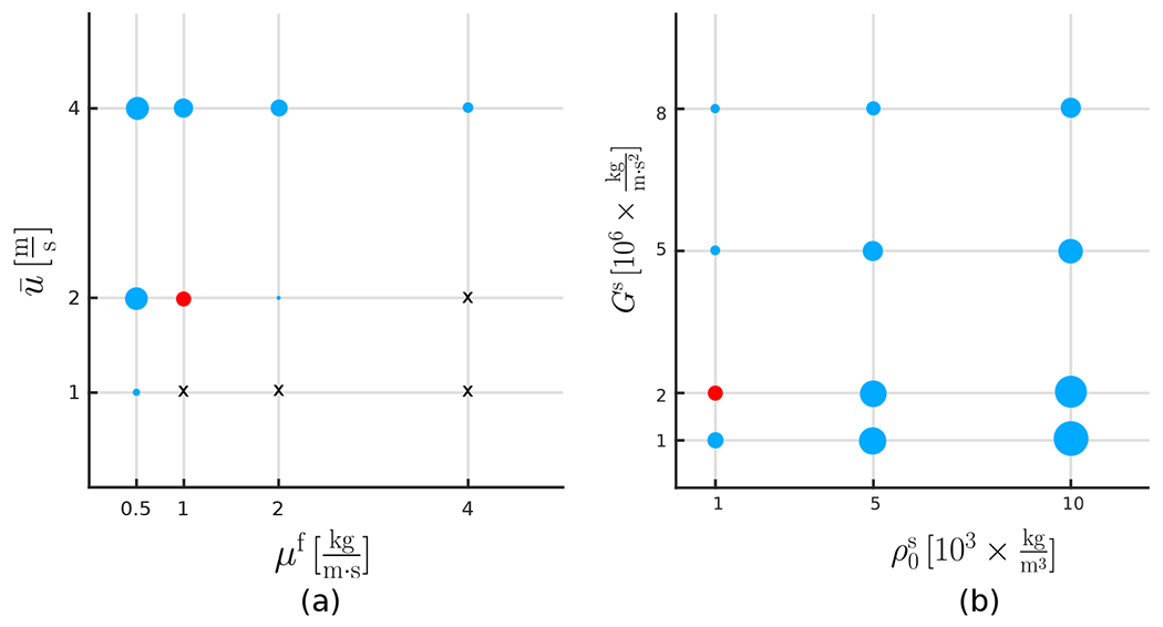
(a) The vertical oscillation amplitude of point A at the flexible tail shown for a range of fluid viscosity and inlet mean velocity using case 2 of Table 1 as the default case with fixed values of and . The vertical amplitude sizes are depicted as blue circles of different diameters. The amplitude of given for case 2 of Table 2 is shown in color red as a reference size for comparison. (b) The vertical displacement of point A at the flexible tail shown for a range of solid density and shear modulus using case 2 of Table 1 as the default case with fixed values of and . As in panel (a), the amplitude of corresponding to case 2 of Table 2 (shown in color red) is used as a reference size for comparison. The ( pairs shown by “✕” correspond to cases for which no apparent oscillations are observed.
4.3. Damped structural instability of a fully enclosed fluid reservoir 3
To test our ILE formulation for compressible solid material interacting with an enclosed fluid domain, we consider a banded fluid domain that is surrounded by two rigid inlet channels and two thin curved structures with neo-Hookean material and different stiffness. This benchmark was introduced by Küttler et al. [63]. Here we consider a version of the problem with connecting inlet channels extended twice as long to ensure that the deformed configuration of the lower band will not fall outside of the computational domain. The schematic of the system, boundary conditions and the dimensions are shown in Fig. 16. The full computational domain is , and is discretized using a refinement ratio of with Cartesian grid levels with a grid spacing of on the coarsest level. As usual, we use elements for the solid structure with . The time step size is , and the force penalty parameters are set to and with . At both inflow boundaries a fully developed velocity profile is prescribed with the right inlet having a slightly larger maximum velocity than the left inlet vs. . Zero normal traction and tangential velocity conditions are imposed at remaining sides of the embedding Cartesian domain. The fluid domain is loaded with the body force . A Saint Venant-Kirchhoff constitutive model for the undamped shell is assumed using Young moduli and for the top and bottom bands, respectively. It is important to note that in this example, fluid-structure interaction only takes place between the inner fluid region within the reservoir and the interior sides of flexible bands. Zero displacement conditions are imposed at the tails of both bands. Traction-free conditions are imposed on the exterior sides of both bands. In other words, although the reservoir is embedded in a larger computational domain, in practice, the flexible structures do not “feel” the effect of the nonphysical fluid region that is present in the computation but outside of the reservoir. Because the FSI coupling only takes place on one side of the structures, this also makes it possible to solve for compressible structures, as detailed in Sec. 2.2.2.
Figure 16:
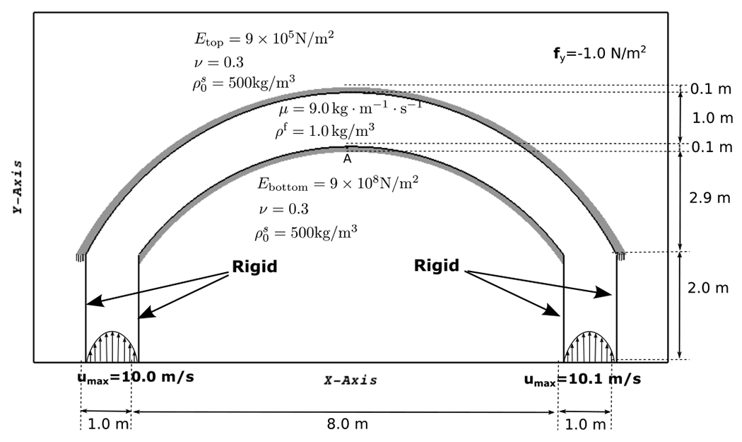
The problem description and boundary conditions of the fully enclosed fluid reservoir.
Because of the injected inflow at both inlets, the fluid pressure gradually increases inside the reservoir. It is expected that the softer top band first deforms to create space for the entering fluid. Once a critical pressure builds inside the reservoir, the stiffer bottom band collapses, and from that point forward the pressure rapidly increases in the domain. Fig. 17 shows the pressure field and velocity magnitudes for multiple snapshots of the simulation. It is important to note that our ILE formulations naturally handles the solution for the fluid pressure within the reservoir as part of the solution in the larger computational domain. Typical partitioned formulations with Dirichlet-Neumann coupling require special treatments to handle an undetermined pressure that lies in the null space of the pressure solver for a fluid region fully embedded within a solid structure [63, 91]. Around time , it is clear that the onset of the lower band collapsing is observed. This is concurrent with large pressure built-up in the reservoir prior to that shown in Fig. 17. We observe that despite minor differences in the problem setup, our results are qualitatively in good agreement with Küttler et al. [63], which uses an augmented Dirichlet-Neumann approach; specifically, the collapse of the lower band and the structural instability have been captured in our results. We note that the time at which the bottom band starts to buckle was not explicitly reported in the original study by Küttler et al. [63], but in a later work by Fernández et al. [92] using a fully decoupled time-marching scheme, the midpoint deformation of the lower band revealed a buckling time closer to . A more recent study by Akbay et al. [91] using a partitioned boundary pressure projection method reported for the onset of the bottom band buckling.
Figure 17:
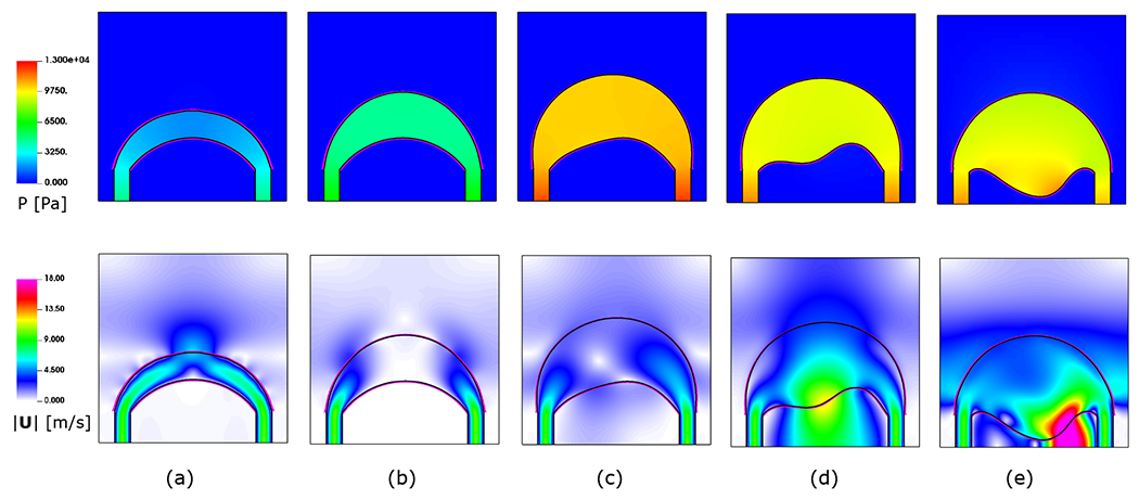
The contours of pressure (top) and velocity magnitudes (bottom) for the damped structural instability of the enclosed fluid reservoir at times (a) , (b) , (c) , (d) , and (e) .
In addition, we have tested the multirate time-stepping feature of our ILE formulation for this problem. Fig. 18 shows the magnitude of the displacement vector for a material point located at the mid-point of the lower flexible band over time. The first simulation uses a time step of and as before, but in the second simulation, we have increased the fluid time step to ms while keeping the structural time step size fixed by using . The displacement magnitude of the midpoint at the lower flexible band is recorded over time and plotted for both simulations. There is an excellent agreement between the cases. The sudden collapse of the lower band after inaction time of resistance against the pressure load is clearly observed. The maximum deformation of the mid-point around appears to match the maximum deformation previously reported by Fernández et al. [92].
Figure 18:
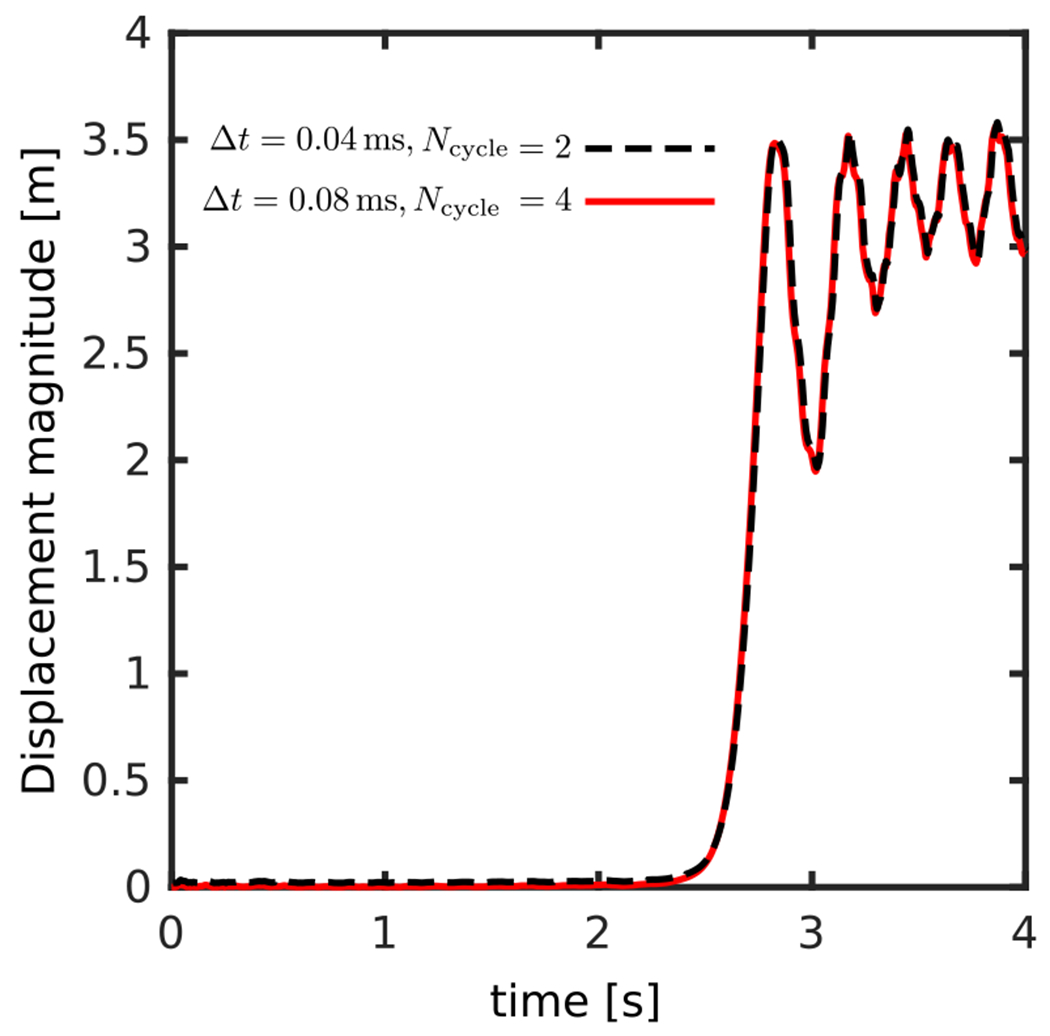
The displacement magnitude of the bottom band’s mid-point over time. The sudden collapse of the lower band after some time is apparent. Results show two choices with two values showing the multirate time-stepping capability of the algorithm in predicting essentially identical results.
4.4. Horizontal flexible plate inside a flow phantom 4
This section considers a three-dimensional FSI benchmark based on experimental results originally proposed by Hessenthaler et al. [64]. This test involves an elastic beam clamped inside a flow phantom on one end and free on the other end moving inside the enclosure; see Fig. 19 for the geometrical dimensions of the setup. Two inlet pipes of diameter merge into one large outlet with diameter . The housing is a stationary surface structure tethered in place by spring forces. The filament (shown in red in Fig. 19) has dimensions . The computational domain is , a cuboid of size . This Eulerian domain is discretized using a refinement ratio of with Cartesian grid levels yielding a grid spacing of on the coarsest level. The time step size is with . The rigid housing is described using our underlying immersed interface formulation for discrete surfaces [53] with a spring penalty parameter of . The penalty parameters for the filament are and . The physical parameters of the test are given in Table 3. is the frequency of the applied velocity field. Note that in the original work the Poisson’s ratio is , but here we use in our nearly incompressible formulation. The numerical tests are performed in three stages: the hydrostatic; a steady phase I; and a transient phase II.
Figure 19:
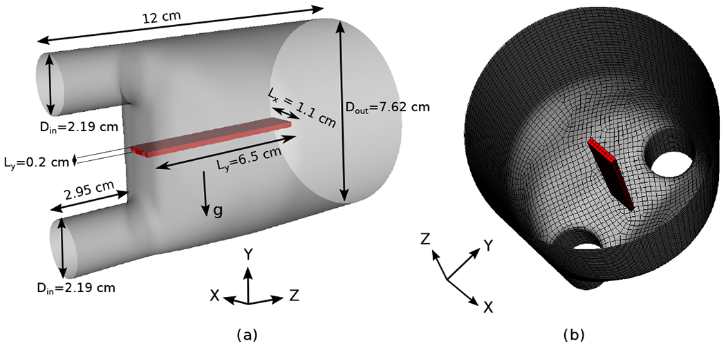
(a) Geometrical dimensions and (b) mesh for the flexible plate inside a flow phantom. The gravitational force is directed towards the negative -axis.
Table 3:
Physical parameters for the horizontal flexible plate inside a flow phantom benchmark (Sec. 4.4). We use a nearly incompressible material unlike the original work that uses .
| Case | ||||||||
|---|---|---|---|---|---|---|---|---|
| Hydrostatic | (0, 0, 0) | (0, 0, 0) | - | 0.1250 | 1.1633 | 1.0583 | 0.499 | |
| Phase I | (0, 0, 61.5) | (0, 0, 63.0) | - | 0.1250 | 1.1633 | 1.0583 | 0.499 | |
| Phase II | See Fig. 22(a) | See Fig. 22(a) | 1/6 | 0.1337 | 1.1640 | 1.0583 | 0.499 |
Fig. 20(a) shows the hydrostatic equilibrium solution under gravity with . The solution at has reached the equilibrium state matching the measurements from the experiment. For the phase I experiment, fully developed parabolic inflow boundary conditions are used with zero velocity in the and directions and peak velocity in the direction given as,
| (50) |
| (51) |
Zero fluid traction is applied at the outflow and the boundary conditions at the remaining sides of the Eulerian domain’s boundary is set to zero velocity. The simulation is run until a steady-state condition is reached. Fig. 20(b) shows the steady-state solution for the displacement of the center-line of the silicon beam at . Overall, there is a good agreement with the experimental data reported by Hessenthaler et al. [64]. Some discrepancies could be attributed to the fact that the outflow condition is imposed at an outlet that is not far enough from the filament. In Fig. 21(a) the velocity magnitudes of the steady-state solution at is shown along with the equilibrium position of the silicon beam in Fig. 21(b) colored by the magnitude of the steady-state wall shear stress.
Figure 20:
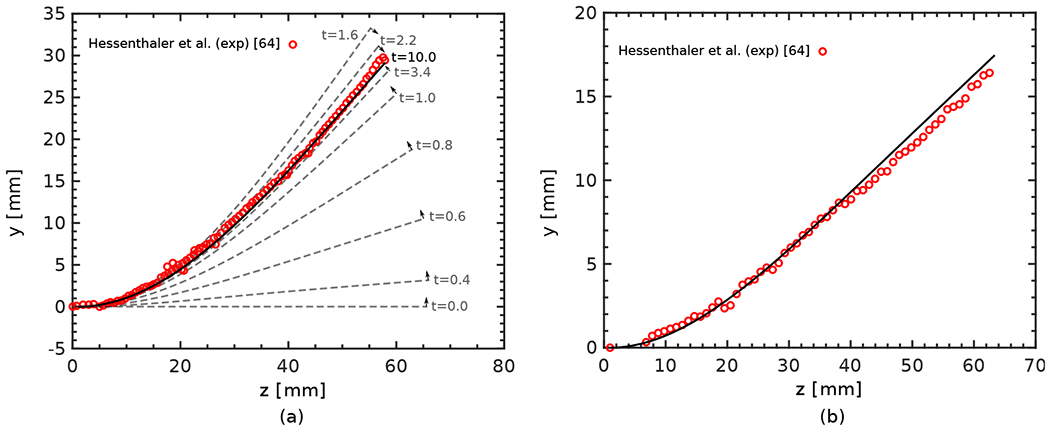
(a) The hydrostatic response for the -position of the silicone filament centerline inside the flow phantom, and (b) the displacement of the silicone filament center-line in the Phase I experiment. Red circles show measured experimental data by Hessenthaler et al. [64].
Figure 21:
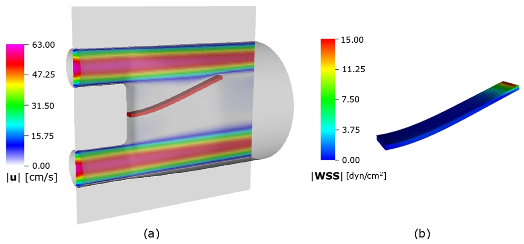
Simulation results of the horizontal flexible plate inside a flow phantom including (a) steady-state velocity magnitudes at and (b) equilibrium position of the silicon beam including contour of steady-state wall shear stress (WSS) magnitudes.
To perform phase II of the benchmark, a pulsatile inflow, according to the peak velocity values in Fig. 22(a), is imposed at the inlets except that the component of the velocity at the bottom inlet is set to . The frequency of the pulsatile velocity is and we run the simulation for two periods up to . Fig. 22(b) shows sample displacements of the filament’s centerline for two separate times and their comparisons with experimental data. Additional qualitative comparison of the magnitude of the component velocity with MRI measurement obtained by Hessenthaler et al. [64] on plane at time is shown Fig. 22(c). Although some discrepancies can be observed in the details of the velocity distribution, the overall magnitude and peak locations are generally in good agreement.
Figure 22:
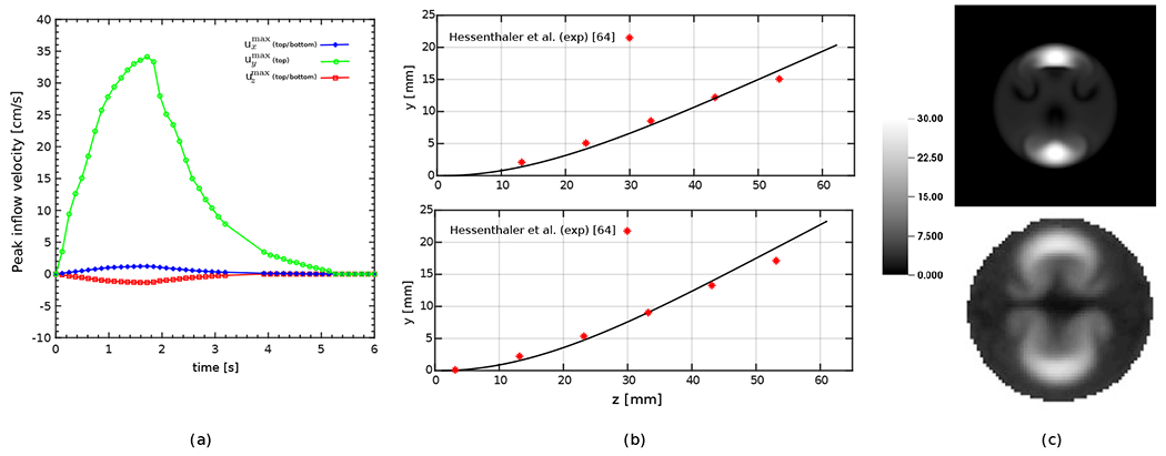
The Phase II benchmark of the flexible plate inside a flow phantom: (a) Measured peak inflow velocity of the parabolic profiles based on data from Hessenthaler et al. [64] used as boundary conditions of the top inlet. The bottom inlet uses the same velocity profile as the top inlet except using for the -component. (b) Sample results of the deformation of the flexible plate including the centerline’s -position at (top) and (bottom). Red stars show measured data by Hessenthaler et al. [64]. (c) velocity component magnitudes at at the time for the present simulation (top) and the MRI measurements [64] (bottom).
4.5. Clot trapping of the FDA generic IVC filter
IVC filters are medical devices implanted in the IVC to capture blood clots from the lower extremities before they migrate to a patient’s lungs and cause a pulmonary embolism. Here we perform simulations to demonstrate the capability of using the present method to model the migration and trapping of a realistic flexible blood clot by an IVC filter. The challenging aspects of this model result from the relatively large size of the clot that affects the local fluid dynamics, the large deformations that occur, and contact between the clot and the IVC filter. In principle, the ILE formulation will naturally handle contact between immersed structures given sufficient spatial resolution. However, resolving contact for thin structures like the IVC filter is challenging because of the practical difficulties of resolving not just the thin struts, which have a width and thickness of approximately , but also the fluid boundary layers in the vicinity of the struts. For this case, we implemented a simple penalty-based contact model [93] to prevent interpenetration. This was done by locally adding opposing concentrated loads on nodes of the boundary of the volumetric solid structure where the fronts of two nearby structures come in close contact. In our computations, this force is added along with the interface forces of the exterior fluid in Eq. (21). The weak formulation takes the form
| (52) |
in which is the surface force density obtained from the simple penalty-based contact model by Kamensky et al. [93].
The IVC filter used in this study is a new generic conical-type filter, referred to as the GENI (GEneric NItinol) filter, that is designed for research purposes by U.S. Food and Drug Administration (FDA) scientists and collaborators [65]. It resembles a cage with support structure of an umbrella consisting of a central hub with 16 evenly spaced radial struts. We simulate the dynamics of clot transport and capture with the filter deployed in a rigid circular tube that is representative of the IVC. Blood is modeled as a Newtonian fluid with the density and dynamic viscosity realistic cylindrical blood clot with length and diameter is considered. The blood clot is modeled as a nearly incompressible hyperelastic material with Poisson’s ratio , shear modulus , and density . Here we ignore the influence of gravity. The clot and the filter are deployed in a circular tube of length and diameter . A fully developed parabolic velocity profile with the maximum velocity of is imposed at the inlet of the tube at the bottom boundary , corresponding to the total flow rate of . Zero normal traction and tangential velocity conditions are imposed at the outlet of the tube at the top boundary. No-slip conditions are imposed along all the other parts of the Cartesian domain boundary. The computational domain is a cuboid of size . This Eulerian domain is discretized using mixed refinement ratios, including two Cartesian grid levels with a refinement ratio of four and additional three Cartesian grid levels with refinement ratios of two, resulting effective Cartesian grid spacings of on the coarsest level and on the finest level. Note that while it is not necessary to use a mixed refinement ratio, our numerical experiments show that in some large scale simulations a mixed refinement ratio provides a reasonable compromise between the overall computational cost and additional refinement in regions where higher accuracy is desired. Both the IVC filter and the circular tube are assumed to be rigid, stationary structures that are modeled using penalty methods [53]. The time step size is and and the force penalty parameters for the clot are set to and .
Fig. 23(a) shows the initial setup of the problem including the geometries of the clot, filter, and the circular tube. The clot is positioned at an initial angle of with the axis, and its center of mass is initially located at .
Figure 23:
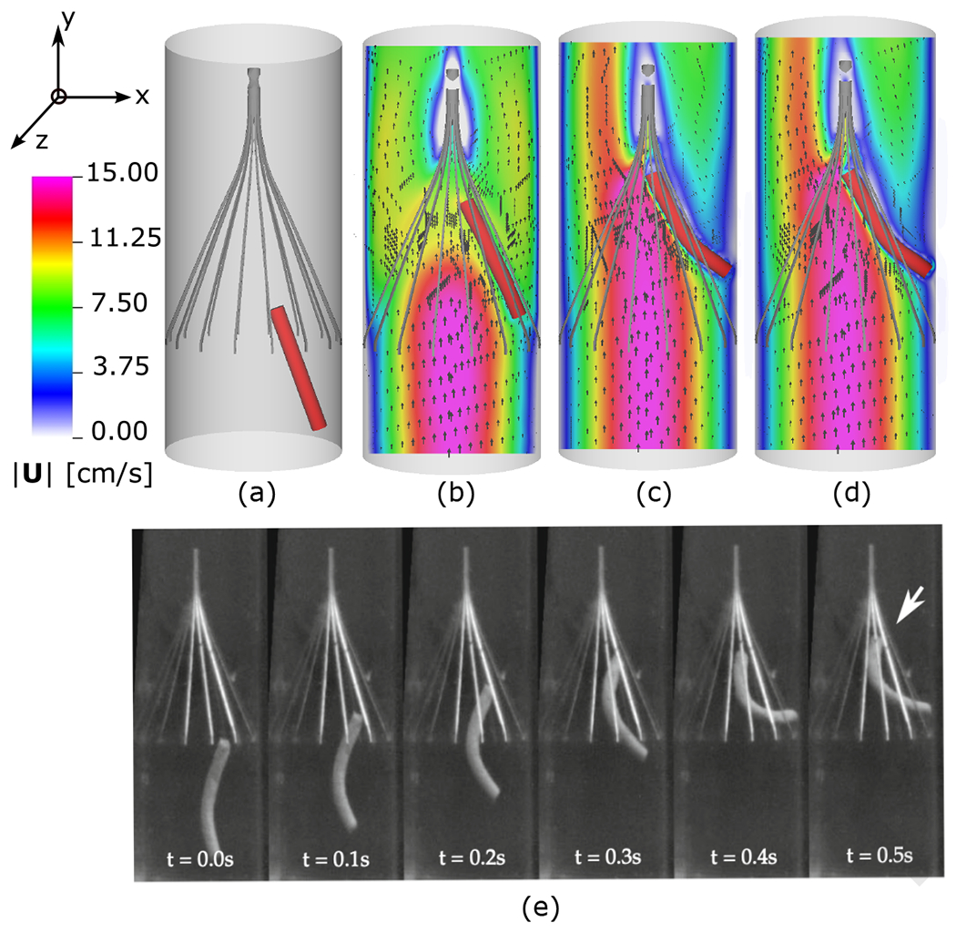
Simulations of the capturing of a geometrically realistic, deformable clot in the IVC filter deployed in a rigid circular tube showing (a) the initial clot-filter-tube configuration. Dynamics of the clot deformation along with contours of velocity magnitude and vectors on the plane are shown for times: (b) , (c) , and (d) . (e) Image sequence from high-speed videography of a similar cylindrical blood clot trapped in the IVC filter [65] showing similar clot trapping dynamics.
In the present methodology, the dynamics of the clot deformation along with the velocity distribution in the mid-plane are shown in Fig. 23(b)–(d) at three different times. The clot is captured by the filter at . As the simulation proceeds, the clot continues to contact the filter while undergoing deformations caused as a result of the clot interaction with the local fluid field. The dynamics of the clot’s deformation follow similar patterns as experimental observations from recent in vitro experiments using the same model IVC device [65].
5. Summary and conclusions
This paper introduces a partitioned sharp interface immersed approach for modeling flexible structures interacting with a Newtonian fluid. It extends our recently developed rigid body immersed Lagrangian-Eulerian method for FSI [12] to models involving immersed flexible structures. The partitioned aspect of our formulation provides the flexibility of taking a broad range of solid to fluid density ratios and using multi-rate time-stepping that allows for separate choices of time-step sizes in the fluid and solid mechanics solvers. These features are in addition to general advantages of immersed formulations, including geometrical flexibility and fast domain solution capability for large deformation FSI. The Dirichlet-Neumann coupling strategy only connects fluid and solid subproblems through interface conditions, unlike alternative fictitious domain approaches that use distributed Lagrange multiplier to hold the constraint in the entire space occupied by the structure. The deformations of the structure are determined as a result of interplay between the forces of intrinsic stresses associated with the solid constitutive model and the exterior fluid traction forces that are computed from the fluid solver using physical jump conditions and imposed as boundary conditions to the solid domain. We then use the deformation of the flexible structure to determine the motion of the fluid along the fluid-structure interface via a penalty method. The dynamics of the volumetric structural mesh are determined using a standard finite element approach to large-deformation nonlinear elasticity via a nearly incompressible solid mechanics formulation. We also demonstrate the method’s capability for modeling compressible solid structures if the fluid subdomain is completely enclosed within the structure. Pointwise second-order accuracy of the difference norm between the positions of the two representations of the fluid-structure interface as well as a second-order accuracy for the structural volume of the soft disk in a lid driven cavity are achieved. For the structural position of the disk’s centroid, between first and second-order spatiotemporal convergence is observed in the norm over the entire simulation. To assess and validate the robustness and accuracy of the new algorithm, comparisons are made with computational and experimental FSI benchmarks in two and three dimensions. Through our benchmark test cases, we demonstrate test cases with different density ratios including smaller, equal and larger than one. We previously reported the ability of the method in modeling problems with various density ratios for rigid-body FSI [12]. Though rigorous stability analyses and analytical investigations still remain to be done and are beyond the aim of the current extension of the method, our numerical experiments herein provided further evidence that the ILE formulation can handle flexible-body FSI problems with large added mass effects. A rigorous mathematical analysis of the stability of the methodology could be the subject of future investigation. Finally, we show representative results from applications of this methodology to the transport and capture of a geometrically realistic, deformable blood clot in an inferior vena cava filter.
Future work could address further applications of this method to more challenging problems in biomedical fluid-structure interaction. Numerical approaches that use fully incompressible structural formulations, including a more sophisticated exactly incompressible and implicit elasticity formulation, can be developed. Additionally, the current formulation requires the structure to have a finite thickness. A surface representation with higher regularity can be considered in future work that allows for imposing higher order jump conditions, more accurate traction calculations on the solid boundary and higher order structural deformation. Further extensions on the fluid solver for more accurate simulation of large Reynolds number phenomena could consider higher-order spatial discretizations and large-eddy simulation (LES) turbulence modeling.
Highlights.
This paper introduces a a sharp-interface approach to simulating fluid-structure interaction (FSI) involving flexible bodies described by general nonlinear material models and across a broad range of mass density ratios.
This paper extends our earlier work to integrate partitioned and immersed approaches to FSI by generalizing our recently developed immersed Lagrangian-Eulerian formulation for fluid-rigid structure interaction to problems involving flexible structures described by nonlinear elastic material models.
Our numerical approach incorporates the geometrical and domain solution flexibility of the immersed boundary method with an accuracy comparable to body-fitted approaches that sharply resolve flows and stresses up to the fluid-structure interface.
The partitioned aspect of our formulation provides the flexibility of taking a broad range of solid to fluid density ratios and using multi-rate time-stepping that allows for separate choices of time-step sizes in the fluid and solid mechanics solvers. These features are in addition to general advantages of immersed formulations, including geometrical flexibility and fast domain solution capability for large deformation FSI.
The immersed interface formulation in our approach enables us to evaluate exterior fluid traction along the fluid-structure interface described by the C0 continuous surface representation.
Our approach can also be viewed as a distributed Lagrange multipliers scheme that uses interfacial, rather than volumetric, FSI coupling.
To assess and validate the robustness and accuracy of the new algorithm, comparisons are made with computational and experimental FSI benchmarks in two and three dimensions. Through our benchmark test cases, we demonstrate test cases with different density ratios including smaller, equal and larger than one.
Selected grid convergence studies demonstrate second-order convergence in volume conservation and in the pointwise discrepancies between corresponding positions of the two interface representations as well as between first and second-order convergence in the structural displacements. We additionally demonstrate second-order convergence for the time integration of the algorithm.
Finally, we show representative results from applications of this methodology to the transport and capture of a geometrically realistic, deformable blood clot in an inferior vena cava filter.
Acknowledgements
We acknowledge research support through NIH (Awards U01HL143336 and R01HL157631) and NSF (DMS 1664645, CBET 175193, OAC 1652541, and OAC 1931516) and the U.S. FDA Center for Devices and Radiological Health (CDRH) Critical Path program. This research was supported in part by an appointment to the Research Participation Program at the U.S. FDA administered by the Oak Ridge Institute for Science and Education through an interagency agreement between the U.S. Department of Energy and FDA. The findings and conclusions in this article have not been formally disseminated by the FDA and should not be construed to represent any agency determination or policy. The mention of commercial products, their sources, or their use in connection with material reported herein is not to be construed as either an actual or implied endorsement of such products by the Department of Health and Human Services. Computations were performed using facilities provided by University of North Carolina at Chapel Hill through the Research Computing division of UNC Information Technology Services.
Footnotes
Publisher's Disclaimer: This is a PDF file of an unedited manuscript that has been accepted for publication. As a service to our customers we are providing this early version of the manuscript. The manuscript will undergo copyediting, typesetting, and review of the resulting proof before it is published in its final form. Please note that during the production process errors may be discovered which could affect the content, and all legal disclaimers that apply to the journal pertain.
This benchmark test is provided in IBAMR version 0.11.0 or newer, within the directory examples/IIM/ex7.
This benchmark test is provided in IBAMR version 0.11.0 or newer, within the directory examples/IIM/ex6.
This benchmark test is provided in IBAMR version 0.11.0 or newer, within the directory examples/IIM/ex8.
This benchmark test is provided in IBAMR version 0.11.0 or newer, within the directory examples/IIM/ex9.
Declaration of interests
The authors declare that they have no known competing financial interests or personal relationships that could have appeared to influence the work reported in this paper.
References
- [1].Nobile F, Formaggia L, A stability analysis for the arbitrary Lagrangian Eulerian formulation with finite elements, East-West Journal of Numerical Mathematics 7 (2) (1999) 105–132. [Google Scholar]
- [2].Farhat C, Geuzaine P, Grandmont C, The discrete geometric conservation law and the nonlinear stability of ALE schemes for the solution of flow problems on moving grids, Journal of Computational Physics 174 (2) (2001) 669–694. [Google Scholar]
- [3].Cottrell JA, Hughes TJ, Bazilevs Y, Isogeometric analysis: Toward integration of CAD and FEA, John Wiley & Sons, 2009. [Google Scholar]
- [4].Degand C, Farhat C, A three-dimensional torsional spring analogy method for unstructured dynamic meshes, Computers & Structures 80 (3-4) (2002) 305–316. [Google Scholar]
- [5].Luke E, Collins E, Blades E, A fast mesh deformation method using explicit interpolation, Journal of Computational Physics 231 (2) (2012) 586–601. [Google Scholar]
- [6].Peskin CS, Flow patterns around heart valves: A numerical method, Journal of Computational Physics 10 (2) (1972) 252–271. [Google Scholar]
- [7].Peskin CS, Numerical analysis of blood flow in the heart, Journal of Computational Physics 25 (3) (1977) 220–252. [Google Scholar]
- [8].Peskin CS, The immersed boundary method, Acta Numerica 11 (2002) 479–517. [Google Scholar]
- [9].Griffith BE, Patankar NA, Immersed methods for fluid–structure interaction, Annual Review of Fluid Mechanics 52 (2020) 421–448. [DOI] [PMC free article] [PubMed] [Google Scholar]
- [10].Mittal R, Iaccarino G, Immersed boundary methods, Annual Review of Fluid Mechanics 37 (2005) 239–261. [Google Scholar]
- [11].Sotiropoulos F, Yang X, Immersed boundary methods for simulating fluid–structure interaction, Progress in Aerospace Sciences 65 (2014) 1–21. [Google Scholar]
- [12].Kolahdouz EM, Bhalla AP, Scotten LN, Craven BA, Griffith BE, A sharp interface Lagrangian-Eulerian method for rigid-body fluid–structure interaction, Journal of Computational Physics 443 (2021) 110442. [DOI] [PMC free article] [PubMed] [Google Scholar]
- [13].McQueen DM, Peskin CS, A three-dimensional computer model of the human heart for studying cardiac fluid dynamics, ACM Siggraph Computer Graphics 34 (1) (2000) 56–60. [Google Scholar]
- [14].McQueen DM, Peskin CS, Heart simulation by an immersed boundary method with formal second-order accuracy and reduced numerical viscosity, in: Mechanics for a New Millennium, Springer, 2001, pp. 429–444. [Google Scholar]
- [15].Griffith BE, Peskin CS, On the order of accuracy of the immersed boundary method: Higher order convergence rates for sufficiently smooth problems, Journal of Computational Physics 208 (1) (2005) 75–105. [Google Scholar]
- [16].Griffith BE, Hornung RD, McQueen DM, Peskin CS, An adaptive, formally second order accurate version of the immersed boundary method, Journal of Computational Physics 223 (1) (2007) 10–49. [Google Scholar]
- [17].Zhang L, Gerstenberger A, Wang X, Liu WK, Immersed finite element method, Computer Methods in Applied Mechanics and Engineering 193 (21-22) (2004) 2051–2067. [Google Scholar]
- [18].Zhang LT, Gay M, Immersed finite element method for fluid-structure interactions, Journal of Fluids and Structures 23 (6) (2007) 839–857. [DOI] [PMC free article] [PubMed] [Google Scholar]
- [19].Boffi D, Gastaldi L, Heltai L, Peskin CS, On the hyper-elastic formulation of the immersed boundary method, Computer Methods in Applied Mechanics and Engineering 197 (25-28) (2008) 2210–2231. [Google Scholar]
- [20].Gil AJ, Carreno AA, Bonet J, Hassan O, The immersed structural potential method for haemodynamic applications, Journal of Computational Physics 229 (22) (2010) 8613–8641. [Google Scholar]
- [21].Gil AJ, Carreno AA, Bonet J, Hassan O, An enhanced immersed structural potential method for fluid-structure interaction, Journal of Computational Physics 250 (2013) 178–205. [Google Scholar]
- [22].Devendran D, Peskin CS, An immersed boundary energy-based method for incompressible viscoelasticity, Journal of Computational Physics 231 (14) (2012) 4613–4642. [Google Scholar]
- [23].Griffith BE, Luo XY, Hybrid finite difference/finite element version of the immersed boundary method, International Journal for Numerical Methods in Biomedical Engineering 33 (11) (2017) e2888 (31 pages). [DOI] [PMC free article] [PubMed] [Google Scholar]
- [24].Wells D, Vadala-Roth B, Lee JH, Griffith BE, A nodal immersed finite element-finite difference method (2021). arXiv:2111.09958. [DOI] [PMC free article] [PubMed] [Google Scholar]
- [25].Baaijens FP, A fictitious domain/mortar element method for fluid-structure interaction, International Journal for Numerical Methods in Fluids 35 (7) (2001) 743–761. [Google Scholar]
- [26].Hesch C, Gil AJ, Carreno AA, Bonet J, Betsch P, A mortar approach for fluid–structure interaction problems: Immersed strategies for deformable and rigid bodies, Computer Methods in Applied Mechanics and Engineering 278 (2014) 853–882. [Google Scholar]
- [27].Nestola MGC, Becsek B, Zolfaghari H, Zulian P, De Marinis D, Krause R, Obrist D, An immersed boundary method for fluid-structure interaction based on variational transfer, Journal of Computational Physics 398 (2019) 108884. [Google Scholar]
- [28].Glowinski R, Pan T-W, Periaux J, A fictitious domain method for Dirichlet problem and applications, Computer Methods in Applied Mechanics and Engineering 111 (3-4) (1994) 283–303. [Google Scholar]
- [29].Glowinski R, Pan T-W, Hesla TI, Joseph DD, A distributed Lagrange multiplier/fictitious domain method for particulate flows, International Journal of Multiphase Flow 25 (5) (1999) 755–794. [Google Scholar]
- [30].Van Loon R, Anderson PD, De Hart J, Baaijens FP, A combined fictitious domain/adaptive meshing method for fluid–structure interaction in heart valves, International Journal for Numerical Methods in Fluids 46 (5) (2004) 533–544. [Google Scholar]
- [31].Yu Z, A DLM/FD method for fluid/flexible-body interactions, Journal of Computational Physics 207 (1) (2005) 1–27. [Google Scholar]
- [32].Bhalla APS, Bale R, Griffith BE, Patankar NA, A unified mathematical framework and an adaptive numerical method for fluid–structure interaction with rigid, deforming, and elastic bodies, Journal of Computational Physics 250 (2013) 446–476. [Google Scholar]
- [33].Boffi D, Cavallini N, Gastaldi L, The finite element immersed boundary method with distributed Lagrange multiplier, SIAM Journal on Numerical Analysis 53 (6) (2015) 2584–2604. [Google Scholar]
- [34].Kadapa C, Dettmer W, Perić D, A fictitious domain/distributed Lagrange multiplier based fluid–structure interaction scheme with hierarchical B-spline grids, Computer Methods in Applied Mechanics and Engineering 301 (2016) 1–27. [Google Scholar]
- [35].de Tullio MD, Pascazio G, A moving-least-squares immersed boundary method for simulating the fluid–structure interaction of elastic bodies with arbitrary thickness, Journal of Computational Physics 325 (2016) 201–225. [Google Scholar]
- [36].Vanella M, Balaras E, Direct Lagrangian forcing methods based on moving least squares, in: Immersed Boundary Method, Springer, 2020, pp. 45–79. [Google Scholar]
- [37].Spandan V, Lohse D, de Tullio MD, Verzicco R, A fast moving least squares approximation with adaptive Lagrangian mesh refinement for large scale immersed boundary simulations, Journal of Computational Physics 375 (2018) 228–239. [Google Scholar]
- [38].Sugiyama K, Ii S, Takeuchi S, Takagi S, Matsumoto Y, A full Eulerian finite difference approach for solving fluid–structure coupling problems, Journal of Computational Physics 230 (3) (2011) 596–627. [Google Scholar]
- [39].Valkov B, Rycroft CH, Kamrin K, Eulerian method for multiphase interactions of soft solid bodies in fluids, Journal of Applied Mechanics 82 (4), 041011 (04 2015). [Google Scholar]
- [40].Rycroft CH, Wu C-H, Yu Y, Kamrin K, Reference map technique for incompressible fluid-structure interaction, Journal of Fluid Mechanics 898 (2020) A9. [Google Scholar]
- [41].Richter T, A fully Eulerian formulation for fluid–structure-interaction problems, Journal of Computational Physics 233 (2013) 227–240. [Google Scholar]
- [42].Richter T, Wick T, Finite elements for fluid–structure interaction in ALE and fully Eulerian coordinates, Computer Methods in Applied Mechanics and Engineering 199 (41-44) (2010) 2633–2642. [Google Scholar]
- [43].Mayer UM, Popp A, Gerstenberger A, Wall WA, 3D fluid–structure-contact interaction based on a combined XFEM FSI and dual mortar contact approach, Computational Mechanics 46 (1) (2010) 53–67. [Google Scholar]
- [44].Burman E, Fernández MA, An unfitted Nitsche method for incompressible fluid–structure interaction using overlapping meshes, Computer Methods in Applied Mechanics and Engineering 279 (2014) 497–514. [Google Scholar]
- [45].Zonca S, Vergara C, Formaggia L, An unfitted formulation for the interaction of an incompressible fluid with a thick structure via an XFEM/DG approach, SIAM Journal on Scientific Computing 40 (1) (2018) B59–B84. [Google Scholar]
- [46].Wall WA, Gerstenberger A, Gamnitzer P, Förster C, Ramm E, Large deformation fluid-structure interaction–advances in ALE methods and new fixed grid approaches, in: Fluid-structure interaction, Springer, 2006, pp. 195–232. [Google Scholar]
- [47].Banks JW, Henshaw WD, Schwendeman DW, Deforming composite grids for solving fluid structure problems, Journal of Computational Physics 231 (9) (2012) 3518–3547. [Google Scholar]
- [48].Miller ST, Campbell R, Elsworth C, Pitt J, Boger D, An overset grid method for fluid-structure interaction, World Journal of Mechanics 4 (7) (2014). [Google Scholar]
- [49].Serino DA, Banks JW, Henshaw WD, Schwendeman DW, A stable added-mass partitioned (AMP) algorithm for elastic solids and incompressible flow, Journal of Computational Physics 399 (2019) 108923. [Google Scholar]
- [50].Mittal R, Dong H, Bozkurttas M, Najjar F, Vargas A, Von Loebbecke A, A versatile sharp interface immersed boundary method for incompressible flows with complex boundaries, Journal of Computational Physics 227 (10) (2008) 4825–4852. [DOI] [PMC free article] [PubMed] [Google Scholar]
- [51].Massing A, Larson M, Logg A, Rognes M, A Nitsche-based cut finite element method for a fluid-structure interaction problem, Communications in Applied Mathematics and Computational Science 10 (2) (2015) 97–120. [Google Scholar]
- [52].Schott B, Ager C, Wall WA, Monolithic cut finite element-based approaches for fluid-structure interaction, International Journal for Numerical Methods in Engineering 119 (8) (2019) 757–796. [Google Scholar]
- [53].Kolahdouz EM, Bhalla APS, Craven BA, Griffith BE, An immersed interface method for discrete surfaces, Journal of Computational Physics 400 (2020) 108854. [DOI] [PMC free article] [PubMed] [Google Scholar]
- [54].Xu S, Wang ZJ, An immersed interface method for simulating the interaction of a fluid with moving boundaries, Journal of Computational Physics 216 (2) (2006) 454–493. [Google Scholar]
- [55].Xu S, The immersed interface method for simulating prescribed motion of rigid objects in an incompressible viscous flow, Journal of Computational Physics 227 (10) (2008) 5045–5071. [Google Scholar]
- [56].Le D-V, Khoo BC, Peraire J, An immersed interface method for viscous incompressible flows involving rigid and flexible boundaries, Journal of Computational Physics 220 (1) (2006) 109–138. [Google Scholar]
- [57].Tan Z, Le D-V, Lim KM, Khoo B, An immersed interface method for the incompressible Navier–Stokes equations with discontinuous viscosity across the interface, SIAM Journal on Scientific Computing 31 (3) (2009) 1798–1819. [Google Scholar]
- [58].Tan Z, Lim K, Khoo B, A level set-based immersed interface method for solving incompressible viscous flows with the prescribed velocity at the boundary, International Journal for Numerical Methods in Fluids 62 (3) (2010) 267–290. [Google Scholar]
- [59].Thekkethil N, Sharma A, Level set function–based immersed interface method and benchmark solutions for fluid flexible-structure interaction, International Journal for Numerical Methods in Fluids 91 (3) (2019) 134–157. [Google Scholar]
- [60].Layton AT, Using integral equations and the immersed interface method to solve immersed boundary problems with stiff forces, Computers & Fluids 38 (2) (2009) 266–272. [Google Scholar]
- [61].Zhao H, Freund JB, Moser RD, A fixed-mesh method for incompressible flow–structure systems with finite solid deformations, Journal of Computational Physics 227 (6) (2008) 3114–3140. [Google Scholar]
- [62].Turek S, Hron J, Proposal for numerical benchmarking of fluid-structure interaction between an elastic object and laminar incompressible flow, in: Fluid-Structure Interaction, Springer, 2006, pp. 371–385. [Google Scholar]
- [63].Küttler U, Förster C, Wall WA, A solution for the incompressibility dilemma in partitioned fluid–structure interaction with pure Dirichlet fluid domains, Computational Mechanics 38 (4) (2006) 417–429. [Google Scholar]
- [64].Hessenthaler A, Gaddum N, Holub O, Sinkus R, Röhrle O, Nordsletten D, Experiment for validation of fluid-structure interaction models and algorithms, International Journal for Numerical Methods in Biomedical Engineering 33 (9) (2017) e2848. [DOI] [PMC free article] [PubMed] [Google Scholar]
- [65].Riley J, Price N, Saaid H, Good B, Aycock K, Craven B, Manning K, In vitro clot trapping efficiency of the FDA generic inferior vena cava filter in an anatomical model: An experimental fluid–structure interaction benchmark, Cardiovascular Engineering and Technology (2021) 1–14. [DOI] [PubMed] [Google Scholar]
- [66].Förster C, Wall WA, Ramm E, Artificial added mass instabilities in sequential staggered coupling of nonlinear structures and incompressible viscous flows, Computer Methods in Applied Mechanics and Engineering 196 (7) (2007) 1278–1293. [Google Scholar]
- [67].Liu J, Jaiman RK, Gurugubelli PS, A stable second-order scheme for fluid–structure interaction with strong added-mass effects, Journal of Computational Physics 270 (2014) 687–710. [Google Scholar]
- [68].Young YL, Chae EJ, Akcabay DT, Hybrid algorithm for modeling of fluid-structure interaction in incompressible, viscous flows, Acta Mechanica Sinica 28 (4) (2012) 1030–1041. [Google Scholar]
- [69].Sansour C, On the physical assumptions underlying the volumetric-isochoric split and the case of anisotropy, European Journal of Mechanics-A/Solids 27 (1) (2008) 28–39. [Google Scholar]
- [70].Vadala-Roth B, Acharya S, Patankar NA, Rossi S, Griffith BE, Stabilization approaches for the hyperelastic immersed boundary method for problems of large-deformation incompressible elasticity, Computer Methods in Applied Mechanics and Engineering 365 (2020) 112978. [DOI] [PMC free article] [PubMed] [Google Scholar]
- [71].Flory P, Thermodynamic relations for high elastic materials, Transactions of the Faraday Society 57 (1961) 829–838. [Google Scholar]
- [72].Malkus DS, Hughes TJ, Mixed finite element methods-reduced and selective integration techniques: A unification of concepts, Computer Methods in Applied Mechanics and Engineering 15 (1) (1978) 63–81. [Google Scholar]
- [73].Griffith BE, An accurate and efficient method for the incompressible Navier–Stokes equations using the projection method as a preconditioner, Journal of Computational Physics 228 (20) (2009) 7565–7595. [Google Scholar]
- [74].Griffith BE, Immersed boundary model of aortic heart valve dynamics with physiological driving and loading conditions, International Journal for Numerical Methods in Biomedical Engineering 28 (3) (2012) 317–345. [DOI] [PubMed] [Google Scholar]
- [75].Griffith BE, On the volume conservation of the immersed boundary method, Communications in Computational Physics 12 (2) (2012) 401–432. [Google Scholar]
- [76].Strang G, On the construction and comparison of difference schemes, SIAM Journal on Numerical Analysis 5 (3) (1968) 506–517. [Google Scholar]
- [77].Hua M, Peskin CS, An analysis of the numerical stability of the immersed boundary method, Journal of Computational Physics 467 (2022) 111435. [Google Scholar]
- [78].IBAMR: An adaptive and distributed-memory parallel implementation of the immersed boundary method, https://github.com/IBAMR/IBAMR.
- [79].SAMRAI: Structured Adaptive Mesh Refinement Application Infrastructure, http://www.llnl.gov/CASC/SAMRAI.
- [80].Hornung RD, Kohn SR, Managing application complexity in the SAMRAI object-oriented framework, Concurrency and Computation 14 (5) (2002) 347–368. [Google Scholar]
- [81].Balay S, Abhyankar S, Adams MF, Benson S, Brown J, Brune P, Buschelman K, Constantinescu EM, Dalcin L, Dener A, Eijkhout V, Gropp WD, Hapla V, Isaac T, Jolivet P, Karpeev D, Kaushik D, Knepley MG, Kong F, Kruger S, May DA, McInnes LC, Mills RT, Mitchell L, Munson T, Roman JE, Rupp K, Sanan P, Sarich J, Smith BF, Zampini S, Zhang H, Zhang H, Zhang J, PETSc Web page, https://petsc.org/ (2021).
- [82].hypre: High performance preconditioners, http://www.llnl.gov/CASC/hypre.
- [83].Falgout RD, Yang UM, hypre: A library of high performance preconditioners, in: International Conference on Computational Science, Springer, 2002, pp. 632–641. [Google Scholar]
- [84].Kirk BS, Peterson JW, Stogner RH, Carey GF, libmesh: A C++ library for parallel adaptive mesh refinement/coarsening simulations, Engineering with Computers 22 (3) (2006) 237–254. [Google Scholar]
- [85].Wang X, Zhang LT, Interpolation functions in the immersed boundary and finite element methods, Computational Mechanics 45 (4) (2010) 321–334. [Google Scholar]
- [86].Roy S, Heltai L, Costanzo F, Benchmarking the immersed finite element method for fluid–structure interaction problems, Computers & Mathematics with Applications 69 (10) (2015) 1167–1188. [Google Scholar]
- [87].Zhang Z-Q, Liu G, Khoo BC, A three dimensional immersed smoothed finite element method (3D IS-FEM) for fluid–structure interaction problems, Computational Mechanics 51 (2) (2013) 129–150. [Google Scholar]
- [88].Lee JH, Griffith BE, On the Lagrangian-Eulerian coupling in the immersed finite element/difference method, Journal of Computational Physics 457 (2022) 111042. [DOI] [PMC free article] [PubMed] [Google Scholar]
- [89].Bhardwaj R, Mittal R, Benchmarking a coupled immersed-boundary-finite-element solver for large-scale flow-induced deformation, AIAA Journal 50 (7) (2012) 1638–1642. [Google Scholar]
- [90].Tian F-B, Dai H, Luo H, Doyle JF, Rousseau B, Fluid–structure interaction involving large deformations: 3D simulations and applications to biological systems, Journal of Computational Physics 258 (2014) 451–469. [DOI] [PMC free article] [PubMed] [Google Scholar]
- [91].Akbay M, Schroeder C, Shinar T, Boundary pressure projection for partitioned solution of fluid-structure interaction with incompressible Dirichlet fluid domains, Journal of Computational Physics 425 (2021) 109894. [Google Scholar]
- [92].Fernández MA, Landajuela M, Vidrascu M, Fully decoupled time-marching schemes for incompressible fluid/thin-walled structure interaction, Journal of Computational Physics 297 (2015) 156–181. [Google Scholar]
- [93].Kamensky D, Hsu M-C, Schillinger D, Evans JA, Aggarwal A, Bazilevs Y, Sacks MS, Hughes TJ, An immersogeometric variational framework for fluid–structure interaction: Application to bioprosthetic heart valves, Computer Methods in Applied Mechanics and Engineering 284 (2015) 1005–1053. [DOI] [PMC free article] [PubMed] [Google Scholar]


