

Abstract
Purpose:
The purpose of this study was to evaluate the efficacy of cone-beam computed tomography (CBCT) navigation to achieve percutaneous screw fixation (PSF) of pelvic bone metastases (PBM).
Materials and methods:
Thirty-five consecutive patients (12 men and 23 women; mean age, 62 ± 11.3 [SD]; range: 39–89 years) treated between 2019 and 2021 were retrospectively included. CBCT navigation software was systematically used. Manual drawing of the entry point (MDEP) was performed when CBCT automatic positioning failed. Influence of metastasis pattern, ablation, body mass index, number of screws, and MDEP on procedure duration (PD) and total Air Kerma (AK) was evaluated. Local pain was assessed before, one and six months after treatment. Variables were compared using Pearson correlation, Student t and Wilcoxon tests.
Results:
Seventy-five screws were inserted successfully (mean: 2.1 ± 1.1 [SD]; range: 1–5 per patient). CBCT automatic positioning was obtained for 41 screws (55%, 41/75), whereas 34 (45%, 34/75) required MDEP. Mean procedure duration, fluoroscopy time, kerma air product and AK were 73.3 ± 44.8 (SD) min (range: 19–233 min), 13.1 ± 9.5 (SD) min (range: 1.4–38.6 min), 73.8 ± 66.3 (SD) Gy.cm2 (range: 11.6–303.7 Gy.cm2)and 301.7 ± 242.1 (SD) mGy (range: 49.4–1111.5 mGy), respectively. Procedure duration was not significantly longer in patients with mixed or blastic PBM compared to those with lytic PBM or when performing ablation, and no significant correlations were observed with the number of screws inserted (P = 0.19), MDEP (P = 0.37) and BMI (P = 0.44). No adverse events were reported during the follow-up (median: 6 months; IQR: 6–6.5 months). Thirteen patients died during the follow-up related to cancer progression. Local pain decreased from 35 ± 32 (SD) mm (range: 0–10 mm) to 11 ± 20 (SD) mm (range: 0–80 mm) at one month (P = 0.001); and to 22 ± 23 (SD) mm (range: 0–60 mm) at six months (P = 0.001).
Conclusion:
CBCT navigation allows to effectively performing PSF of PBM even in the presence of steep angulations.
Keywords: Neoplasms, Cone-beam computed tomography, Fixation, Interventional radiology, Pain management
1. Introduction
Metastases of pelvic bone have a major impact on the quality of life of patients with cancer due to inherent pain and limitations [1–4]. Pain is related to tumor burden causing fracture and periosteal inflammation [5–7]. Functional disability is linked to the biomechanical alteration of the bone [8]. Stabilization is therefore needed to obtain pain relief but used to require complex surgical interventions. However, the risks and morbidity of which often outweigh potential benefits in patients with cancer with altered physical conditions [9,10]. Therefore, percutaneous cementoplasty and internal screw fixation have be considered as a less invasive option to allow rapid pain relief and functional recovery with low morbidity and short procedure recovery in these cancer patients with potential limited life expectancy [11–14]. These techniques reinforce the bone by helping to transmit the load, while limiting the effect of stresses on an altered bone [8,15].
Such percutaneous procedures may require multiple screw insertions in several directions to build a three-dimensional frame, which may be eased by image guidance using computed tomography (CT) or cone-beam CT (CBCT) [13,16]. Imaging can improve targeting accuracy and speed, lower radiation dose and provide more comfortable setup [17–20]. However, limitations of imaging guidance may be observed due to the steep angulation often required for proper screw insertion in the pelvic bone. The automatic bull’s eye view provided by CBCT showing the entry point and direction may not be reachable due to conflicts of the c-arm with the table or patient’s body in these angulations. Anatomical landmarks [21,22] or further assistance by navigation software [16,23] may thus be required.
The purpose of this study was to evaluate the efficacy of CBCT navigation to achieve percutaneous screw fixation of pelvic bone metastases.
2. Materials and methods
2.1. Patients
This retrospective study was approved by the Internal Review Board of the Institution and informed consent was waived. From 2019 to 2021, all consecutive patients who had percutaneous screw fixation of the pelvic bone performed under CBCT guidance were included (Fig. 1). Patients were referred to the interventional radiology and oncology department, where fixation was offered as a local palliative treatment option to obtain stabilization of the bone and pain relief after multidisciplinary discussion. All patients presented with pelvic bone metastases. All patients agreed with this option discussed during multidisciplinary team meeting.
Fig. 1.

Flowchart of patient selection. CBCT indicates cone beam computed tomography.
2.2. Procedures
The procedures were performed by five interventional radiologists with 1- (L. R.), 2- (M. N.), 3- (M. BA.), 10- (M. B.) and 15 years (F. C.) of experience in an angiography suite equipped with a 40 × 40 cm detector (Innova 4100, GE Healthcare) with patients placed prone and under general anesthesia. An initial CBCT examination was acquired to assess anatomic abnormalities and plan the approach to the pelvic bone. To obtain an adequate insertion of screws, a three-dimensional (3D) planning and guidance software (Needle ASSIST, GE Healthcare) was used (Figs. 2 and 3). Projections of the trajectory were represented in real-time overlaid on live fluoroscopy. When possible, the system was automatically positioned in a bull’s eye view, providing both the skin entry point and the planned orientation of the needle. After insertion in the planned orientation, the system was automatically positioned in a progress view for advancement to the target depth. When the bull’s eye view was not reachable due to conflicts of the C-arm with the table or the patient and if non-amendable by repositioning the table or the patient, the entry point was obtained at the intersection of two lines manually drawn on the skin of the patient along the planned trajectory in two different orthogonal views, as indicated by the software (Fig. 3). Once inserted, trocars or needles were guided along the planned trajectory using automatic progress views.
Fig. 2.

Needle guidance with manual drawing of entry point for steep trans-iliac screw placement.
A- Optimal trajectories are planned after reconstruction of the cone beam CT images using dedicated software. As bull’s eye view of the iliac track (arrows) was not reachable due to steep angulation, drawing of the entry point was decided.
B- Using automatic progress view, a guidewire on the skin was superimposed on the planned trajectory overlaid on live fluoroscopy (arrowhead).
C- A first line was drawn on the skin along the guidewire.
D- Using a second progress view in an orthogonal projection, the guidewire on the skin was superimposed again on the planned trajectory (arrowhead).
E- A new line was drawn and the intersection of the two lines corresponded to the entry point (arrow).
F- The 10 G trocar was inserted through the skin at this point and advanced sequentially along two orthogonal progress views until it reached the bone. Then a guidewire was used to insert the screw along a projection provided by the navigation software allowing visualizing the progression.
Fig. 3.
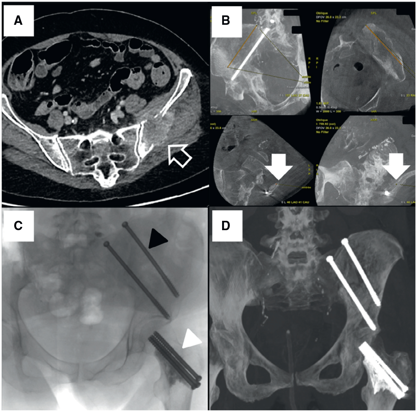
56-year-old woman with history of lung carcinoma presenting walk limitation and pain.
A, Transverse reconstruction of an enhanced computed tomography shows large lytic metastasis (arrow) involving the left arcuate line of ilium.
B, Trajectory planning of the two trans iliac and the femoral neck screws. As bull’s eye view of the iliac track (arrows) was not reachable due to steep angulation, drawing of the entry point was decided.
C, Oblique projection showing the final assessment of the screws both on coxal bone and femoral neck after cement injection (black arrowhead: trans-iliac and white arrowhead: femoral neck screws).
D, Maximum intensity projection CT image obtained at 6-month follow-up shows no displacement of the material.
For each patient, a 10-cm bone 10-G trocar was first inserted manually (Stryker) (Fig. 2) or using a power driver (Arrow OnControl Powered Bone Access System, Teleflex). Then, a 2.8 mm guidewire was positioned through the trocar, the trocar was removed and a stainless-steel 6.5-mm cannulated screw (DepuySynthes, Johnson & Johnson) was inserted on the guidewire (Figs. 3 and 4) and locked on the cortical bone. A 3D stereotaxic reconstruction based on two fluoroscopy projections (Stereo3D software, Needle ASSIST, GE Healthcare) or a full CBCT was performed to assess needle placement versus the planned trajectory and adjust needle progress as needed. In case of mixed or blastic lesions, a surgical orthopedic power drill was used (Stryker). Trajectory length indicated by the software allowed screw length selection. A 3D stereotaxic reconstruction was performed from table side for intermediate assessment with no workflow interruption. Polymethyl-methylacrylate (Vertaplex HV; Stryker) was finally injected through the screw to provide additional consolidated effect at the tip of the screw while the screw heads remained in the cortical bone.
Fig. 4.

55-year-old man with history of lung carcinoma and left iliac fossa pain.
A, CT image in the axial plane shows large lytic lesion (arrow) involving the sacrum and coxal bone. This lesion was treated by cryoablation just before fixation.
B, CT image in the axial plane shows another lesion (arrow) of the acetabulum involving the posterior column.
C, Fluoroscopic image in oblique projection shows final assessment of screws fixation after cement injection. A three-dimensional frame was built with a sacro-iliac, a trans-iliac, and an ischiatic screw. Manual drawing of the entry point was performed for the posterior trans-iliac (black arrowhead) and trans-ischiatic screws (white arrowhead), whereas automatic bulls eye view was used for the trans-sacroiliac screw.
D, Maximum intensity projection CT image obtained at 6-month follow-up shows no displacement of the material.
2.3. Endpoints
Procedural endpoints included the technical success reflecting the ability to adequately place the screws which encompasses: the number of screws placed, the number of manual drawing of the entry point reflecting bulls eye feasibility for entry point guidance, the procedure time (time ranged between first and last image acquisitions) and the total Air Kerma dose (AK). Patients’ body mass index (BMI), fluoroscopy time (FT), Kerma area product (KAP) and pre-/post-procedure local pain levels using visual analog scale (VAS), which consists of a straight 10-cm line at the end points defining extreme limits such as ‘no pain at all’ and ‘pain as bad as it could be’ [24] evaluated before, one and six months after the procedure, and all available imaging were reviewed in patients charts. Adverse events, including fracture or displacement, were assessed using the CIRSE classification system [25]. Those data were extracted from a Picture Archiving and Communication System (Carestream V12.1.6.0117, Philips Healthcare) and a dose monitoring system (DoseWatch, GE HealthCare).
2.4. Statistical analysis
Continuous variables were reported as means ± standard deviations (SD) and ranges or medians and interquartile ranges (IQR). Qualitative variables were expressed as raw numbers, proportions and percentages. Correlations between variables were assessed using Pearson correlation test to determine the relationship between procedure duration or FT and AK; and between the number of CBCT acquisitions performed, number of screws inserted, number of drawing of entry points, or BMI, and procedure duration or AK. AK and procedure duration were compared between the different patterns of lesions (i.e., lytic versus mixed or blastic) using Student t-test. Mean VAS before, one and six months after the procedure were compared using Wilcoxon test in surviving patients. P values < 0.05 were considered to indicate statistically significant differences. Statistical analysis was performed using SPSS 20.0 software (SPSS, Inc).
3. Results
A total of 35 patients were included. There were 12 men and 23 women with a mean age of 62 ± 11.3 [SD] years (range: 39–89 years). All had previously undergone chemotherapy; only two received radiation therapy before fixation. Nine patients (9/35; 25.7%) had percutaneous ablation just before screw insertions, including one who underwent cryoablation (Endocare Inc, Varian), three radiofrequency ablations (Osteocool, Medtronic) and five microwave ablations (Neuwave, Johnson & Johnson). Patients’ characteristics are summarized in Table 1. Mean body mass index was 24.5 ± 5.3 (SD) kg/m2 (range: 15.3–41.7 kg/m2).
Table 1.
Patients characteristics and outcomes.
| Patient# | Gender | Age(year) | BMI(kg/m2) | Disease | Lesion pattern | Total No. of screws | No ofscrews needing entry point drawing | Procedure time (min) | Fluoro scopy time (min) | Kerma Area Product (Gy.cm2) | TotalAir Kerma (mGy) | Concomitant procedure | Radiation therapy after fixation* |
|---|---|---|---|---|---|---|---|---|---|---|---|---|---|
| 1 | F | 77 | 25..6 | LC | Lytic & cortical disruption | 3 | 2 | 103 | 10.77 | 184.53 | 532.62 | MWA | 1 |
| 2 | M | 55 | 27.5 | LC | Lytic & cortical disruption | 3 | 2 | 75 | 16.0 | 97.1 | 331.1 | Cryoablation | 0 |
| 3 | F | 59 | 26.6 | BC | Mixed | 3 | 2 | 64 | 12.7 | 65.8 | 260.4 | 0 | 0 |
| 4 | M | 73 | 18.6 | LC | Lytic | 1 | 1 | 27 | 4.4 | 16.9 | 67.9 | 0 | 1 |
| 5 | F | 69 | 22.1 | LC | Mixed | 2 | 1 | 80 | 15.1 | 78.8 | 278.7 | 0 | 0 |
| 6 | F | 62 | 28.4 | BC | Mixed | 4 | 1 | 101 | 26.6 | 174.4 | 607.7 | 0 | 1 |
| 7 | F | 56 | 22.8 | LC | Lytic & cortical disruption | 5 | 4 | 130 | 38.5 | 94.8 | 433.5 | MWA | 0 |
| 8 | F | 72 | 19.7 | LC | Lytic | 2 | 1 | 37 | 6.0 | 18.3 | 60.5 | 0 | 0 |
| 9 | F | 69 | 25.8 | CC & CRC | Lytic | 5 | 1 | 128 | 17.2 | 75.6 | 624.7 | 0 | 0 |
| 10 | F | 63 | 32.7 | OC | Mixed | 2 | 1 | 57 | 12.5 | 54.7 | 325.8 | 0 | 0 |
| 11 | M | 69 | 24.6 | LC | Mixed | 2 | 1 | 66 | 17.5 | 48.6 | 310.8 | 0 | 0 |
| 12 | F | 39 | 16.7 | BC | Mixed | 1 | 1 | 30 | 4.5 | 25.0 | 83.5 | 0 | 0 |
| 13 | M | 71 | 22.2 | CRC | Lytic & cortical disruption | 2 | 2 | 110 | 24.6 | 130.4 | 517.5 | 0 | 0 |
| 14 | F | 67 | 22.3 | BC | Blastic | 4 | 2 | 135 | 31.2 | 189.4 | 764.9 | 0 | 0 |
| 15 | F | 62 | 17.3 | LC | Mixed | 3 | 1 | 57 | 11.7 | 38.7 | 152.6 | 0 | 0 |
| 16 | M | 42 | 15.3 | LC | Lytic | 1 | 0 | 51 | 10.5 | 11.6 | 51.9 | RFA | 0 |
| 17 | M | 66 | 25.4 | LC | Lytic | 1 | 0 | 45 | 9.2 | 12.1 | 83.0 | RFA | 0 |
| 18 | M | 56 | 24.3 | HCC | Lytic | 1 | 0 | 233 | 10.8 | 46.0 | 204.2 | 0 | 1 |
| 19 | F | 49 | 24.5 | BC | Lytic | 2 | 0 | 39 | 4.3 | 20.5 | 123.6 | 0 | 1 |
| 20 | F | 74 | 22.5 | UC | Mixed | 2 | 1 | 110 | 24.6 | 130.4 | 517.5 | 0 | 1 |
| 21 | M | 71 | 21.1 | LC | Lytic | 2 | 0 | 39 | 8.4 | 56.0 | 274.4 | 0 | 0 |
| 22 | F | 65 | 18.4 | LC | Lytic & cortical disruption | 1 | 1 | 53 | 12.4 | 19.7 | 92.2 | MWA | 0 |
| 23 | F | 62 | 34.5 | LC | Lytic | 2 | 2 | 116 | 38.6 | 303.7 | 1111.5 | 0 | 0 |
| 24 | M | 55 | 24.6 | UC | Mixed | 2 | 2 | 45 | 5.7 | 50.2 | 173.3 | RFA | 0 |
| 25 | M | 56 | 32.3 | CRC | Mixed | 4 | 0 | 95 | 13.5 | 79.9 | 282.8 | 0 | 0 |
| 26 | F | 85 | 23.5 | EC | Lytic | 2 | 0 | 19 | 3.4 | 12.3 | 49.4 | 0 | 0 |
| 27 | M | 65 | 17.9 | LC | Lytic | 1 | 1 | 94 | 14.5 | 124.3 | 376.2 | MWA | 1 |
| 28 | M | 55 | 24.7 | LC | Lytic | 1 | 0 | 48 | 6.3 | 41.8 | 255.4 | 0 | 0 |
| 29 | F | 42 | 26.3 | BC | Lytic | 2 | 2 | 20 | 1.4 | 19.2 | 82.0 | 0 | 0 |
| 30 | F | 60 | 23.9 | CRC | Lytic | 1 | 0 | 46 | 8.5 | 27.5 | 203.3 | 0 | 0 |
| 31 | F | 89 | 22.3 | BC | Lytic | 2 | 0 | 52 | 7.1 | 45.2 | 210.2 | 0 | 0 |
| 32 | F | 56 | 25 | BC | Lytic & cortical disruption | 3 | 2 | 53 | 6.9 | 22.3 | 101.0 | 0 | 1 |
| 33 | F | 63 | 27.1 | EC | Lytic | 1 | 0 | 52 | 9.5 | 55.4 | 200.5 | 0 | 1 |
| 34 | F | 58 | 41.7 | BC | Lytic | 1 | 0 | 40 | 3.6 | 43.8 | 162.9 | 0 | 0 |
| 35 | F | 43 | 31.6 | LC | Mixed | 1 | 1 | 117 | 10.3 | 169.2 | 653.2 | MWA | 1 |
Note – BC: Breast carcinoma; BMI: Body mass index; CBCT: Cone beam computed tomography; CC: Cervical carcinoma; CRC: Colorectal carcinoma; EC: Endometrial carcinoma; F: Female; HCC: Hepatocellular carcinoma; KAP: Kerma area product; LC: Lung carcinoma; M: Male; MWA: Microwave ablation; OV: Ovarian carcinoma; RFA: Radiofrequency ablation; UC: Urothelial carcinoma.
1 indicates yes and 0 indicates no.
A total of 75 screws were successfully inserted in the planned location. The mean number of screws inserted per patient was 2.1 ± 1.1 (SD) (range: 1–5). A total of 41 entry points (41/75, 55%) was determined using automatic bull’s eye view, whereas 34 (34/75, 45%) required additional manual drawing of the entry point due to steep approaches. Automatic bulls eye view allowed entry points definition in trans-sacroiliac (27/27, 100%), ilio-pubic or posterior ischiatic (8/9, 89%), and trans-iliac (6/26, 23%) tracks. Entry points non-amenable for automatic bull’s eye view were drawn for trans-iliac (20/24, 83%), trans-ischiatic (10/10, 100%), ilio-pubic (1/9, 11%) and hip (3/3, 100%) tracks.
The mean procedure duration was 73.3 ± 44.8 (SD) min (range: 19–233 min). It was not significantly longer for mixed or blastic PBM (79.8 ± 31.9 [SD] min; range: 30–135 min) compared to lytic PBM (70 ± 49.1 [SD]; range: 19–233 min) (P = 0.48). No differences in procedure time were observed between procedures with ablation (71.3 ± 47.3 [SD]; range: 19–233 min) and those without ablation (79.2 ± 32.8 [SD] min; range: 45–130 min) (P = 0.58). No correlations were observed between mean procedure time and the number of screws inserted (r = 0.2253; P = 0.19), the number of drawing of entry points (r = 0.1567; P = 0.37) and BMI (r = 0.136; P = 0.44).
Mean FT was 13.1 ± 9.5 (SD) min (range: 1.4–38.6 min); mean KAP was 73.8 ± 66.3 (SD) Gy.cm2 (range: 11.6–303.7 Gy cm2) and mean AK was 301.7 ± 242.1 (SD) mGy (range: 49.4–1111.5 mGy). No significant differences in AK were found between mixed or blastic PBM (367.6 ± 216.6 [SD] mGy; range: 83.5–764.9 mGy) and lytic PBM (267.4 ± 249.3 [SD] mGy; range: 49.4–1111.5 mGy) (P = 0.22). Similarly, no differences in AK were found between procedures without ablation (303 ± 215.4 [SD] mGy; range: 51.9–653.2 mGy) and those with ablation (301.3 ± 252.3 (SD) mGy; range: 49.4–1111.5 mGy) (P = 0.98). AK strongly ± correlated with FT (r = 0.797; P < 0.0001), moderately with procedure duration (r = 0.6171; P < 0.0001), drawing of entry points (r = 0.4197; P = 0.01) and weakly with the number of screws inserted (r = 0.388; P = 0.002) and BMI (r = 0.3636; P = 0.03).
The procedures were technically successful as all screws were inserted as initially planned in a single session and no severe adverse events were reported. Minor adverse events (pain, hematoma) were reported in 18 patients (18/35; 51%). Patients were discharged between one to five days after the procedure (median, 2 days; IQR: 1–3 days). Thirteen patients (13/35, 37%) received external radiation therapy after the procedure. Neither fracture nor displacement of procedural site was observed on imaging after a median follow-up of 6 months (IQR: 3–8 months) (Figs. 2 and 3). Thirteen patients died during follow-up but only three at less than six months. Under medication including opioids, mean VAS score decreased significantly from 35 ± 32 (SD) mm (range: 0–10 mm) before the procedure to 11 ± 20 (SD) mm (range: 0–80 mm) at one month after the procedure (P = 0.001) and to 22 ± 23 (SD) mm (range: 0–60 mm) at six months (P = 0.001). No correlations was observed in terms of pain relief for mixed or blastic lesions compared to those being lytic (r = 0.2722; P = 0.027).
4. Discussion
Percutaneous screw fixation of pelvic bone was performed successfully in all patients and a single session using CBCT navigation. Manual drawing of the entry point combined with needle navigation software and the use of anatomical landmarks allowed to overcome the challenges associated with the needs for steeper approaches sometimes required for screw insertion in pelvic bone [20]. The technique is reproducible with all angiography systems which should face the same limitation, regardless of their design. The further results showed that the adequate placement of the screw was not affected by the various level of experience of the interventional radiologists, from one to 15 years. This observation suggests that the learning curve may be steep using CBCT and navigation software after a short initial observational training, but further evaluation is needed to address specifically this question.
Performed under CBCT guidance, mean procedure duration of 73.3 min was lower than that of 108 min reported by Roux et al. on 107 procedures and 171 screws inserted [12]. These differences may be related to the use of CBCT and navigation guidance as no correlation was observed with the number of screws inserted, the use of manual drawing and fluoroscopy time. The patients were placed prone or on the side to facilitate multiple screw insertions. It allowed full access to all the entry points without having to mobilize the patients during the procedure performed under general anesthesia. Ablations were performed before screw insertion and blastic lesions required often to use additional devices to drill. Besides, the techniques of screw insertion and cementoplasty were similar to those previously detailed in the literature [11–13,16].
To quantify indirectly the challenge observed during screw insertion under CBCT, the radiation exposure was evaluated in this study in addition to the procedure duration, which may be biased. In this study performed under CBCT guidance, the mean PD, fluoroscopy time, kerma air product and AK were 73.3 min, 13.1 min, 73.8 Gy. cm2, and 301.7 mGy, respectively. All these values remained similar to the proposed reference levels in interventional radiology for a vertebroplasty as required by the European Directive 2013/59/Euratom [26–27]. Under CT guidance, a mean duration of 111 ± 51 min was reported for a technical success achieved in 96% with a total of 76 screws inserted, with a mean number of CT acquisitions during procedures of 6.4 ± 3.0 (SD), a mean dose length product of 1524 ± 953 (SD) mGy.cm and a mean dose area product of 12 ± 8 (SD) Gy cm2 [16]. As any other procedures, when performing fixation, the patientto-detector distance was minimized, the collimation used, the magnification avoided, and the lateral views were less frequently required. Besides, radiation exposure increased which technical challenges such as those observed in multiple screw insertions, or overweighted patients. Manual drawing of the entry point was correlated with dose while not increasing procedure duration. It may reflect the use of additional CBCTs during the procedure as manual drawing was often performed in addition of the initial CBCT when the operator faced challenges such as those observed when the bull’s eye view was not reachable due to conflicts of the C-arm with the table or the patient. The use of preoperative planning, manual drawing and 3D stereotaxic reconstruction based on two fluoroscopy projections has to be evaluated in first intention as all may help to reduce the number of CBCT by allowing assessing needle placement versus the planned trajectory, adjust needle progress as needed and confirm the anticipated screw length [28,29]. As the CBCT navigation software has been systematically used in this study to facilitate the navigation and needle insertions, its specific impact on radiation exposure cannot be evaluated.
The fixation using screw insertion under CBCT guidance allowed effective local pain relief in the oncologic population with metastases involving the pelvic bone at one and six months after the procedure. However, the addition of other systemic treatments (such as chemotherapy, radiation therapy or bisphosphonates) may have confounded pain scores in longer follow-up assessments. Besides, local evolution and progression of the disease itself have resulted in a confounding pain factor rendering this evaluation of pain challenging. Only the lesions visible on the pelvic bones that seemed to be painful were treated and monitored. Multiple bone locations may change the palliative outcome differently, even if technically correctly treated. These results were achieved in a single session for all patients illustrating the high rate of success of the procedure. Several studies have evaluated the biomechanics of the pelvis to improve the understanding of the stresses involved and their effects [20]. In standing position, high shear forces between sacrum and coxal bones are observed due to the load transmitted through the sacroiliac joints [30]. The imbalance between fragilized bone and stresses can result in debilitating mechanical pain, ultimately leading to a decrease in the quality of life, and precipitate pathological fractures [31]. Following the percutaneous screw fixation, neither fracture nor displacement of procedural site was observed on imaging follow-up in this study. When the cortical bone was affected by extensive tumors, screw fixation performed under imaging guidance using CBCT navigation offered therefore a minimally invasive alternative to surgery, allowing to effectively restoring the balance of the pelvic arch.
Our study has some limitations. This is a single-center study and there are variable anatomic locations of screw implantations. Moreover, due to the limited number of patients, a more thorough study is needed. In this retrospective study the accuracy of screw placement compared to a strategy established prior the intervention was not evaluated similarly to what it was performed under CT guidance and electromagnetic navigation limiting the comparison of both techniques [16]. While fixation provides mechanical stabilization, it is possible that there are no differences in terms of efficacy on pain between radiation therapy, cementoplasty, ablations [5], fixation, or any combination of those [6], since outcomes may be difficult to study in patients receiving several concomitant treatments. Although challenging to conduct, head-to-head trials are needed to compare the efficacy between all these options. It would help choose between the different techniques depending on the individual patient and the various challenges observed in the oncologic population.
In conclusion, effective stabilization of the pelvic bone is essential to allow standing position by transferring the spinal load to the legs and improve quality of life of cancer patients. Percutaneous screw fixation of pelvic bone performed with CBCT navigation is feasible and safe. To overcome possible limitations due to steep angulations often involved in this anatomy, the use of navigation software and manual drawing of the entry point directly on the patient’s skin by the interventional radiologist seems efficient. It allows performing this procedure in patients with no other therapeutic alternative to achieve stabilization and pain relief. However, further evaluation is warranted to draw firm conclusions.
Acknowledgement
The authors thank Mrs Aya Rebet, PhD, for her manuscript editing.
Funding
This work did not receive any grant from funding agencies in the public, commercial, or not-for-profit sectors.
Abbreviations
- 3D
Three-dimensional
- AK
Total air
- BMI
Body mass index
- CBCT
Cone beam computed tomography
- CI
Confidence interval
- CT
Computed tomography
- IQR
Interquartile range
- KAP
Kerma area product
- MDEP
Manual drawing of the entry point
- SD
Standard deviation
- VAS
Visual analogic scale
Footnotes
Human rights
The authors declare that the work described has been performed in accordance with the Declaration of Helsinki of the World Medical Association revised in 2013 for experiments involving humans.
Informed consent and patient details
The authors declare that this report does not contain any personal information that could lead to the identification of the patients.
Conflicts of Interest
The authors have no conflicts of interest to declare. The authors did not receive support from any organization for the submitted work.
CRediT authorship contribution statement
Francois H. Cornelis: Conceptualization, Methodology, Software, Validation, Formal analysis, Investigation, Resources, Data curation, Writing – original draft, Writing – review & editing, Visualization, Supervision, Project administration, Funding acquisition. Leo Razakamanantsoa: Investigation, Writing – review & editing. Mohamed Ben Ammar: Investigation, Writing – review & editing. Milan Najdawi: Investigation, Writing – review & editing. Sanaa El-Mouhadi: Writing – review & editing. Francois Gardavaud: Software, Resources, Data curation, Writing – review & editing. Matthias Barral: Writing – review & editing.
References
- [1].Mavrogenis AF, Angelini A, Vottis C, Pala E, Calabrò T, Papagelopoulos PJ, et al. Modern palliative treatments for metastatic bone disease: awareness of advantages, disadvantages, and guidance. Clin J Pain 2016;32:337–50. [DOI] [PubMed] [Google Scholar]
- [2].Kelekis A, Cornelis FH, Tutton S, Filippiadis D. Metastatic osseous pain control: bone ablation and cementoplasty. Semin Intervent Radiol 2017;34:328–36. [DOI] [PMC free article] [PubMed] [Google Scholar]
- [3].Filippiadis D, Tutton S, Kelekis A. Pain management: the rising role of interventional oncology. Diagn Interv Imaging 2017;98:627–34. [DOI] [PubMed] [Google Scholar]
- [4].Garnon J, Koch G, Caudrelier J, Tsoumakidou G, Cazzato RLL, Gangi A. Expanding the borders: image-guided procedures for the treatment of musculoskeletal tumors. Diagn Interv Imaging 2017;98:635–44. [DOI] [PubMed] [Google Scholar]
- [5].Levy J, Hopkins T, Morris J, Tran ND, David E, Massari F, et al. Radiofrequency ablation for the palliative treatment of bone metastases: outcomes from the multicenter OsteoCool tumor ablation post-market study (OPuS One Study) in 100 Patients. J Vasc Interv Radiol 2020;31:1745–52. [DOI] [PubMed] [Google Scholar]
- [6].Lee FY, Latich I, Toombs C, Mungur A, Conway D, Alder K, et al. Minimally invasive image-guided ablation, osteoplasty, reinforcement, and internal fixation (AORIF) for osteolytic lesions in the pelvis and periarticular regions of weight-bearing bones. J Vasc Interv Radiol 2020;31:649–658.e1. [DOI] [PubMed] [Google Scholar]
- [7].Oh DC-S, First L, Rakesh N, Oh H, Gulati A. Inferior and intra-/peri-articular superior sacroiliac joint injection approaches under ultrasound guidance to treat metastasis-related posterior pelvic bone pain. Pain Pract 2020;20:769–76. [DOI] [PMC free article] [PubMed] [Google Scholar]
- [8].Garnon J, Jennings JW, Meylheuc L, Auloge P, Weiss J, Koch G, et al. Biomechanics of the osseous pelvis and its implication for consolidative treatments in interventional oncology. Cardiovasc Intervent Radiol 2020;43:1589–99. [DOI] [PubMed] [Google Scholar]
- [9].Attar S, Steffner R, Avedian R, Hussain W. Surgical intervention of nonvertebral osseous metastasis. Cancer Control 2012;19:113–21. [DOI] [PubMed] [Google Scholar]
- [10].Haidukewych GJ. Metastatic disease around the hip: maintaining quality of life. J Bone Joint Surg 2012;94:22–5. [DOI] [PubMed] [Google Scholar]
- [11].Garnon J, Koch G, Ramamurthy N, Caudrelier J, Rao P, Tsoumakidou G, et al. Percutaneous CT and fluoroscopy-guided screw fixation of pathological fractures in the shoulder girdle: technical report of 3 cases. Cardiovasc Interv Radiol 2016;39:1332–8. [DOI] [PubMed] [Google Scholar]
- [12].Roux C, Tselikas L, Yevich S, Sandes Solha R, Hakime A, Teriitehau C, et al. Fluoroscopy and cone-beam CT-guided fixation by internal cemented screw for pathologic pelvic fractures. Radiology 2019;290:418–25. [DOI] [PubMed] [Google Scholar]
- [13].Deschamps F, de Baere T, Hakime A, Pearson E, Farouil G, Teriitehau C, et al. Percutaneous osteosynthesis in the pelvis in cancer patients. Eur Radiol 2016;26:1631–9. [DOI] [PubMed] [Google Scholar]
- [14].Autrusseau P-A, Garnon J, Bertucci G, Dalili D, De Marini P, Auloge P, et al. Complications of percutaneous image-guided screw fixation: an analysis of 94 consecutive patients. Diagn Interv Imaging 2021;102:347–53. [DOI] [PubMed] [Google Scholar]
- [15].Cornelis FHH, Deschamps F. Augmented osteoplasty for proximal femur consolidation in cancer patients: biomechanical considerations and techniques. Diagn Interv Imaging 2017;98:645–50. [DOI] [PubMed] [Google Scholar]
- [16].Moulin B, Tselikas L, De Baere T, Varin F, Abed A, Debays L, et al. CT guidance assisted by electromagnetic navigation system for percutaneous fixation by internal cemented screws (FICS). Eur Radiol 2020;30:943–9. [DOI] [PubMed] [Google Scholar]
- [17].Tselikas L, Joskin J, Roquet F, Farouil G, Dreuil S, Hakimé A, et al. Percutaneous bone biopsies: comparison between flat-panel cone-beam CT and CT-scan guidance. Cardiovasc Intervent Radiol 2015;38:167–76. [DOI] [PubMed] [Google Scholar]
- [18].Lang M, Rebet A, Tritle BA, Gill AS. An augmented fluoroscopic guidance technique to improve needle placement and cement injection for sacroplasty. Cardiovasc Intervent Radiol 2020;43:1574–7. [DOI] [PubMed] [Google Scholar]
- [19].Hyun SJ, Rhim SC, Kim YJ, Kim YB. A mid-term follow-up result of spinopelvic fixation using iliac screws for lumbosacral fusion. J Korean Neurosurg Soc 2010;48:347–53. [DOI] [PMC free article] [PubMed] [Google Scholar]
- [20].Pel JJM, Spoor CW, Pool-Goudzwaard AL, Hoek Van Dijke GA, Snijders CJ. Biomechanical analysis of reducing sacroiliac joint shear load by optimization of pelvic muscle and ligament forces. Ann Biomed Eng 2008;36:415–24. [DOI] [PMC free article] [PubMed] [Google Scholar]
- [21].Garnon J, De Marini P, Meylheuc L, Dalili D, Cazzato RL, Bayle B, et al. Percutaneous image-guided double oblique anterior approach to the acetabulum for cementoplasty. Clin Radiol 2020;75:964.e7–964.e12. [DOI] [PubMed] [Google Scholar]
- [22].Moulin B, Brisse H, Dutertre G, Brenet O, Queinnec M, Cottu P, et al. CT-guided vertebroplasty of first (C1) or second (C2) cervical vertebra using an electromagnetic navigation system and a transoral approach. Diagn Interv Imaging 2021;102:571–5. [DOI] [PubMed] [Google Scholar]
- [23].Fairbank JC, Pynsent PB. The Oswestry disability index. Spine 2000;25:2940–52. [DOI] [PubMed] [Google Scholar]
- [24].Filippiadis DK, Binkert C, Pellerin O, Hoffmann RT, Krajina A, Pereira PL. Cirse quality assurance document and standards for classification of complications: the cirse classification system. Cardiovasc Intervent Radiol 2017;40:1141–6. [DOI] [PubMed] [Google Scholar]
- [25].Vañó E, Miller DL, Martin CJ, Rehani MM, Kang K, Rosenstein M, et al. ICRP publication 135: diagnostic reference levels in medical imaging. Ann ICRP 2017;46:1–144. [DOI] [PubMed] [Google Scholar]
- [26].Miller DL, Kwon D, Bonavia GH. Reference levels for patient radiation doses in interventional radiology: proposed initial values for US practice. Radiology 2009;253:753–64. [DOI] [PMC free article] [PubMed] [Google Scholar]
- [27].Etard C, Bigand E, Salvat C, Vidal V, Beregi JP, Hornbeck A, et al. Patient dose in interventional radiology: a multicenter study of the most frequent procedures in France. Eur Radiol 2017;27:4281–90. [DOI] [PubMed] [Google Scholar]
- [28].Blum A, Gillet R, Rauch A, Urbaneja A, Biouichi H, Dodin G, et al. 3D reconstructions, 4D imaging and postprocessing with CT in musculoskeletal disorders: past, present and future. Diagn Interv Imaging 2020;101: 693–705. [DOI] [PubMed] [Google Scholar]
- [29].Fishman EK. CT scanning and data post-processing with 3D and 4D reconstruction: are we there yet? Diagn Interv Imaging 2020;101: 691–2. [DOI] [PubMed] [Google Scholar]
- [30].Tanck E, van Aken JB, van der Linden YM, Schreuder HW, Binkowski M, Huizenga H, et al. Pathological fracture prediction in patients with metastatic lesions can be improved with quantitative computed tomography based computer models. Bone 2009;45:777–83. [DOI] [PubMed] [Google Scholar]
- [31].Filippiadis DK, Cornelis FH, Kelekis A. Interventional oncologic procedures for pain palliation. Presse Med 2019;48:e251–6. [DOI] [PubMed] [Google Scholar]