Abstract
Background:
Temporary anchorage devices or mini-implants have gained great attraction due to its capability to provide absolute anchorage, low cost, versatility, and can be loaded immediately after placement.
Aims and Objectives:
The aim of this study is to use FEA analysis to assess the strain and insertion torque of mini-implants on a bone model at two distinct angulations of 45° and 90°.
Materials and Methods:
A computer-aided three-dimensional (3-D) model representing alveolar bone and mini-implants were developed using ANSYS software. Computed tomography scan images of the implant and the alveolar bone were taken and exported in DICOM format for 3-D image processing. The thickness of the bone model is 1 mm. Ti6Al4V orthodontic single and double threaded mini-implants (L = 7 mm, D = 1.5 mm) were inclined at 45° and 90° on to the bone surface to measure the insertion torque and strain produced.
Results:
Maximum insertion torque (MIT) for single-threaded mini implant at 45° and 90° angulations are 20.001 Nmm and 19.977 Nmm, respectively. MIT for double-threaded mini-implants obtained is 19.977 Nmm at 90° and 19.991 Nmm at 45° angulation. The strain of the bone at 90° angulation for single-threaded mini-implant is 0.00893 mm and for single-threaded mini implant at 45° angulation is 0.01257 mm. The strain in double-threaded mini-implant at 90° angulation is 0.0125 mm and that of 45° angulation is 0.01773 mm.
Conclusion:
For maximum stability single-threaded mini-implant with perpendicular insertion, angle is preferred.
Keywords: Finite element analysis, insertion torque, mini-implants, strain
Introduction
Orthodontic treatment requires intraoral anchorage with high resistance to displacement. Intraoral appliances, such as transpalatal arch, nance holding arch, and lingual arch, do not require patient compliance, but cannot provide absolute anchorage three-dimensionally. Currently, mini-implants have gained countless attraction due to its versatility, minimal surgical invasiveness, ability to provide absolute anchorage, and can be loaded immediately after placement. As more percentage of patients are receiving treatment with mini-implants their clinical stability requires more attention.[1-7] The stability of mini-implant plays an important role in osseointegration and mechanical retention. Stability consists of primary and secondary stability.[8] Primary stability is acquired shortly after mini-implant insertion. This plays a crucial role in loading and healing. The length, diameter, number of flutes, thread design, density and thickness of cortical bone, insertion technique, and the insertion site of mini-implants are the factors that contribute to primary stability. Secondary stability is a result of bone regeneration and remodeling.[8] The biological stability of mini-implants is assessed using experimental animals based on loading time and screw design. The mechanical stability of mini-implants is measured using mini-implant design, insertion and removal torque values, and pull-out measurements.[9-15] Hence, the screw design, the quantity and quality of bone in the area of insertion, have an impact on the mini-implant stability after implantation.
The success of mini-implants has been compromised due to excessive torquing forces applied during the insertion of these devices. Torquing forces can also cause necrosis around the surrounding cortical bone. Maximum insertion torque Insertion torque results from frictional resistance between the thread of the screw and its surrounding cortical bone. This is a standard means to analyze mechanical stability of the mini-implants. Maximum insertion torque (MIT) is maximum torque value recorded during the insertion of orthodontic mini-implant and is expressed in Newton centimeters.
On the other hand, Insertion torque can only be measured during the insertion of mini-implants and cannot be used to assess their stability afterward. Since the in vivo assessment of mini-implant mechanics can be technically limited or ethically questionable three-dimensional (3D) finite element analysis (FEA) provide an effective tool for the in vitro analysis of stress, strain, and insertion torque. This is a noninvasive and efficient tool for evaluating biomechanics and the effect of mechanical forces on biological systems.[16] This method is also used for determining stress and deformations in a particular geometry and also to determine the risk of failure and estimate high-stress locations.[17] Even though there are many studies in literature comparing the effect of stress on mini implants at different angulations, only few have combined the effect of strain and insertion torque of mini implants at vertical and oblique angulations on a bone model using FEA. The objective of this study is to evaluate the strain, stress, and insertion torque of single-threaded and double-threaded mini-implants on a bone model at two distinct angulations of 45° and 90° using 3D FEA.
Materials and Methods
For this study, computer-aided 3D models representing mini-implants and alveolar bone were generated using ANSYS software. For this process, computed tomography scan images were taken and exported in DICOM format for 3D image processing. Four bone models were generated using ANSYS software consisted of single and double thread mini-implants inserted in vertical (90°) and oblique (45°) directions. The simulation of the four geometric models with mini-implants was done using FEA.
Modeling of specimens was done using SOLID 186 elements. It includes a 20-node high-order 3D element having quadratic displacement behavior. The element consists of 20 nodes, each with 3° of freedom: Translations in the x, y, and z directions. It supports mixed formulas for simulating deformations of nearly incompressible elastoplastic materials and fully incompressible hyperelastic materials [Figure 1].
Figure 1.
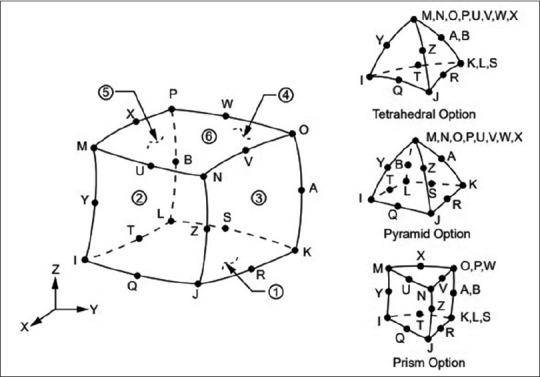
SOLID 186 homogenous structural geometry (ANSYS Library)
Ti-6Al-4V orthodontic mini-implants were used for the study. Models of single-threaded and double-threaded mini-implants were created [Figure 2 and Table 1]. The pitch is 0.7 mm for single-threaded group and 0.35 for double-threaded group. The single-threaded and double threaded mini-implants used were 7.0 mm in length and 1.5 mm diameter.
Figure 2.
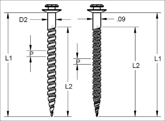
Single-threaded and double-threaded mini-implant
Table 1.
Dimensions of mini-implant model
| Abbreviations | Measurement | TypeT1507 | U3 |
|---|---|---|---|
| D1 | External diameter | 1.45 | 1.45 |
| D2 | Collar diameter | 1.50 | 1.50 |
| D | Internal diameter | 0.95 | 0.95 |
| din | Internal diameter of dual thread | _ | 1.03 |
| L1 | Length of spiral part | 6.00 | 3.20 |
| L2 | Length of dual part | _ | 2.80 |
| L3 | Total length | 7.00 | 7.00 |
| P | Pitch | 0.70 | 0.70 |
| PD | Pitch of dual part | 0.35 |
Modeling of specimens
Four mini-implant models were taken for this study. These models were named as model 1, 2, 3 and 4. All models were of the same dimensions with different threads. First model consists of single-threaded mini-implant inserted at 45° angulation on bone block, model 2 consist of single-threaded mini-implant inserted at 90° angulation to bone block, model 3 consists of dual threaded mini-implant inserted at 45° angulation to bone block and model 4 consist of dual threaded mini-implant inserted at 90° angulation to bone block [Figures 3 and 4]. Models of single- and double-threaded mini-implants were also created [Figure 4]. Modeling was done in ANSYS (ANSYS.Inc Southpointe 2600Ansys Drive, Canonsburg, USA) 19.2 software by using various sketching tools. Meshing was done by the software automatically [Figure 5]. Moments applied to the top surface of the implant for two angulations (90° and 45°). The magnitude of the applied moment is 20 N-mm. The stress concentration developed at the bone mini-implant interface of each was processed and compared with each other.
Figure 3.
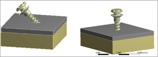
Model 1- single-threaded implant at 45°, Model 2- single-threaded implant at 90
Figure 4.

(a) Single-threaded and double-threaded mini implants. (b) Model 3- double thread at 90°. (c) Model 4- double thread at 45° inclined
Figure 5.
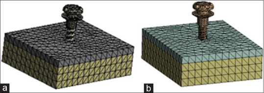
Meshing (a) single thread and (b) double thread
Results
The results of this study show that strain on the bone and mini-implant, deformation of bone and mini-implant, stress on mini-implant is maximum for double-threaded mini-implants inserted at 45° angulations [Table 2].
Table 2.
Deformations of two implants with different loading conditions
| Type of specimen | Type of loading | Deformation of bone (mm) | Deformation of implant (mm) | Strain of bone (mm/mm) | Strain of implant (mm/mm) | Stresses on implant (Mpa) |
|---|---|---|---|---|---|---|
| Single threaded | Vertical | 0.0039407 | 0.025408 | 0.00893 | 0.00217 | 206.08 |
| Inclined | 0.0046347 | 0.031565 | 0,01257 | 0.0024 | 229.5 | |
| Double stranded | Vertical | 0.004029 | 0,029811 | 0.0125 | 0.00256 | 233.66 |
| Inclined | 0.0047304 | 0.0342219 | 0.01773 | 0.00312 | 297.92 |
Single-threaded mini-implant when inserted in bone block at 90° angulation, deformation produced in bone block was 0.003 mm, deformation in mini-implant was 0.025 mm, strain generated in bone was 0.008 mm, strain generated in mini-implant was 0.0027 mm and stress generated in mini-implant was 206 Mpa. Single-threaded mini-implant when inserted in bone block at 45° angulation, deformation produced in bone block was 0.004 mm, deformation in mini-implant was 0.031 mm, strain generated in bone was 0.0125 mm, strain generated in mini-implant was 0.002 mm and stress generated in mini-implant was 229.5 Mpa. Double-threaded mini-implant when inserted in bone block at 90° angulation, deformation produced in bone block was 0.004 mm, deformation in mini-implant was 0.029 mm, strain generated in bone was 0.012 mm, strain generated in mini-implant was 0.002 mm and stress generated in mini-implant was 233.6 Mpa. Double threaded mini-implant when inserted in bone block at 45° angulation, deformation produced in bone block was 0.004 mm, deformation in mini-implant was 0.034 mm, strain generated in bone was 0.012 mm, strain generated in mini-implant was 0.003 mm and stress generated in mini-implant was 297.9 Mpa The insertion torque for single-threaded mini-implants inserted at 90° angulations is 19.97 N mm [Table 2].
Insertion torque was evaluated for a time period of 1 second, a graph was plotted with time (in seconds) in X-axis (0–1 s) and the moment reaction (insertion torque) was plotted in Y–axis. The insertion torque was measured in units of N-mm [Figure 6]. An increase in the insertion torque values was obtained from 0.1 to 1 s. The moment recorded was 1.99 N mm in 0.1 s, which increased to 19.97 N mm in 1 s for single-threaded mini-implant inserted at 90° to bone block [Figure 6 and Table 3].
Figure 6.
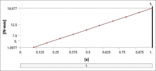
Graph showing time (in seconds) in X-axis (0–1 s) and the moment reaction (insertion torque) in Y-axis. The insertion torque in units of N-mm. single thread at 90°
Table 3.
Insertion torque with increase in time for a single thread implant at 90°
| Time(s) | Moment reaction (total) (Nmm) |
|---|---|
| 0.1 | 1.9977 |
| 0.2 | 3.9954 |
| 0.3 | 5.993 |
| 0.4 | 7.9907 |
| 0.5 | 9.9884 |
| 0.6 | 11.986 |
| 0.7 | 13.984 |
| 0.8 | 15.981 |
| 0.9 | 17.979 |
| 1.0 | 19.977 |
When single-thread mini-implants were placed obliquely [Figure 7], there was an exponential increase in the moment reaction from 2 N mm to 20 N mm from 0.1 to 1 s. There was 10 times increase in the insertion torque values [Table 4]. The insertion torque for double-threaded mini-implants inserted at 90° angulations at 0.1 s is 1.9 and for 1 s is 19.97 N-mm and for double thread mini-implant placed obliquely, the insertion torque values obtained were 1.99 s for 0.1 s and 19.99 for 1 s [Tables 5, 6 and Figures 8 and 9].
Figure 7.

Graph showing time (in seconds) in X-axis (0–1 s) and the moment reaction (insertion torque) in Y-axis. Single threaded at 45°
Table 4.
Tabular column showing the increase in moment reaction with increase in time for a single thread implant inclined in 45°
| Time(s) | Moment reaction (total) Nmm |
|---|---|
| 0.1 | 2.0001 |
| 0.2 | 4.0001 |
| 0.3 | 6.0002 |
| 0.4 | 8.0002 |
| 0.5 | 10.000 |
| 0.6 | 12.000 |
| 0.7 | 14.000 |
| 0.8 | 16.000 |
| 0.9 | 18.001 |
| 1. | 20.001 |
Table 5.
Tabular column showing the increase in moment reaction with increase in time for double thread mini-implant inclined at 90°
| Time(s) | Moment reaction (total) Nmm |
|---|---|
| 0.1 | 1.997 |
| 0.2 | 3.9939 |
| 0.3 | 5.9909 |
| 0.4 | 7.9879 |
| 0.5 | 9.9848 |
| 0.6 | 11.982 |
| 0.7 | 13.979 |
| 0.8 | 15.976 |
| 0.9 | 17.973 |
| 1. | 19.97 |
Table 6.
Tabular column showing the increase in moment reaction with increase in time for double thread implant inclined in 45°
| Time(s) | Moment reaction (total) Nmm |
|---|---|
| 0.1 | 1.9991 |
| 0.2 | 3.9982 |
| 0.3 | 5.9974 |
| 0.4 | 7.9965 |
| 0.5 | 9.9956 |
| 0.6 | 11.995 |
| 0.7 | 13.994 |
| 0.8 | 15.993 |
| 0.9 | 17.992 |
| 1. | 19.991 |
Figure 8.
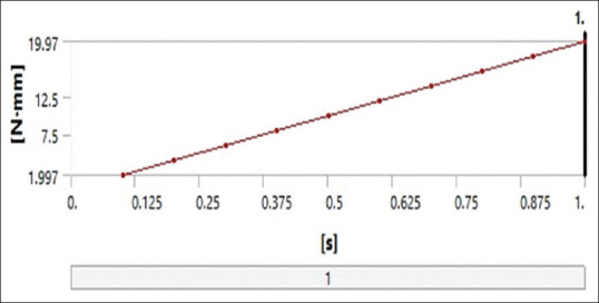
Graph showing time (in seconds) in X-axis (0–1 s) and the moment reaction (insertion torque) in Y-axis. Double thread at 90°
Figure 9.
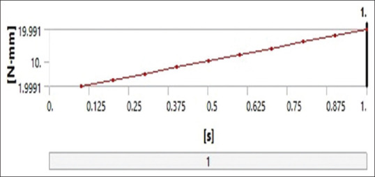
Graph showing time (in seconds) in X-axis (0–1 s) and the moment reaction (insertion torque) in Y-axis. Double thread at 45°
Discussion
There are numerous factors which affect the success of mini-implants such as mini-implant dimensions, mini-implant design, bone quality, angle of insertion, and insertion torque. A detailed study of these factors is important so as to increase the applications of mini-implants in our routine clinical practice. This study was undertaken to evaluate the effect of strain and insertion torque of mini-implants at vertical and oblique angulations on a bone model using 3D FEA.
Bone tissue can remodel in response to mechanical stress. Increased concentration of stress in supporting tissues due to pressure necrosis can lead to mini-implant failure. Therefore, the success of mini-implants depends largely on how these mechanical stresses are transferred from the mini-implant to the surrounding bone.
There are different methods to study the stress in dental structures like brittle coating analysis, strain gauges, and holography. However, these methods are not suitable for dental structures as these involve complex geometries. FEA helps in accurately calculating the stress and strain of all materials including living tissues. This helps to correctly model the teeth for validating clinical assumptions and helps to prove it scientifically. Hence, this provides a better solution for structures involving complex geometries.
In this study, the strain and insertion torque of single and double threaded mini-implants at 45° and 90° angulations are evaluated on a bone model using FEA. Remodeling of bone is affected by strain around the mini-implant. A higher strain value would lead to bone resorption and would be pathological.[18] Strain produced both in bone block and in mini-implant while inserting a mini-implant at vertical angulation was more for double-threaded mini-implant when compared to single-threaded mini-implant. This result was caused because 240 of the difference in mini-implant thread designs. The inter-thread distance is 0.7 mm and 0.35 for single and double thread groups respectively. The internal diameter is wider for the double thread group. Contact area with cortical bone is increased in double-threaded mini-implant which can increase the strain around the mini-implant and the cortical bone. Rossi et al., in their findings, suggested that the strain generated with the 200 gf traction and 20 N cm torsion in mini-implants inserted and 45 and 90° showed that increased strain in bone-implant interface and deformation was seen with a greater angle of inclination and mini-implants with large number of threads[19] Gene Tsu et al. studied how immediately loaded mini-implant length and cortical bone thickness effects the strain at bone mini-implant interface and surrounding bone. In finite element and experimental models, the strain was highly concentrated on just one side of mandible on lateral loading. For single immediately loaded mini-implants, cortical bone thickness affects the bone strain more than the length of implant. If the mini-implants are placed in thick cortical bone, the strain can be reduced.[20] However, in this study only strain around the cortical bone of 1 mm thickness was considered.
There has been a considerable debate whether the insertion angulation should be perpendicular or angulated. Jasmine et al.[21] reported that decrease in stress values was observed in both mini-implants and cortical bone as the insertion angle increased from 30° to 90°. They concluded that ideal mini-implant insertion angulation should be at 90° for enhanced stability The FEA by Perillo et al.[22] advocated that placing mini-implants at 90° angle would result in improved stability than at angulation lesser or >90°.
This argument was also supported by Wilmes et al. who suggested that oblique placement may lead to a slightly greater primary stability, especially in areas with poor or reduced bone quality. To achieve higher insertion torque values insertion angulation ranging from 60° to 70° have also been suggested. This insertion angle proves to be beneficial whenever there is insufficient inter radicular space for mini-implant placement.[23]
To avoid root injury mini-implants are inserted at 30°–45° angulation in maxilla and 10%–20% in mandible instead of perpendicular to bone. Theoretically, a more acute entry angle would result in increased stress because of greater amount of cortical bone that TAD has to penetrate. Increased insertion torque combined with increased stress on bone resulting from placement of mini-implant at an angle may raise the risk of inflammation, leading to mini-implant failure.[24-26]
Hence, mini-implants should be placed perpendicular to bone as long as root damage can be avoided. Marimuthu et al. explained that placing mini-implants perpendicular to the long axis reduces stress concentration around the mini-implant and bone. Moreover, when a mini-implant is inserted at an angle of 45° it resulted in higher stress and deformation of the bone-implant interface. Butcher et al. has explained that severe angulation during insertion can cause slippage of mini-implant bone. Furthermore, obliquely inserted mini-implants, if forces are applied can expose a greater lever arm leading to higher failure rates.[27]
The result of our study supports these previous literatures which suggest that 90° angulation is ideal for mini-implant insertion. Successful long-term mini-implant integration to ensure a successful clinical outcome is positively associated with primary stability. The most important factor for sufficient primary stability is the optimal mini-implant design.[28]
Thread design is important to achieve primary stability.[29] The FEM study by Arenal et al.[30] made a remark that showed the stress distribution of single-threaded mini-implants is more uniform. The advantages presented by double-threaded mini-implants are that due to its large surface area osseointegration is better than single-threaded mini-implants. So, when the bone density is low as in maxilla, dual threaded implant can be used and in mandible where there is increased cortical bone thickness single-threaded mini-implants can be used.
During insertion of mini-implant excessive torque forces will compromise the stability and can cause micro-damage leading to necrosis of the surrounding bone. Cha et al. reported that for single thread mini-implants the MIT was relatively constant, but MIT increased significantly in double-threaded mini-implants with increase in cortical bone thickness.[31] In this study also insertion torque was at the maximum with the double-threaded mini-implant when compared to the single-threaded mini-implant that of same height, size and width.
Yamaguchi et al. concluded that advantage of double threaded mini-implant is the faster insertion rate but higher insertion angle can lead to reduced primary stability, as they cause an increased damage to bone tissue.[32] Kim et al. evaluated the effects of diameter and dual pitch mini-implant of a mini-implant on the insertion and removal torque and concluded that dual pitch groups showed a higher removal torque than the mono-pitch groups.[33]
Increased strain in the bone-implant interface and greater deformation resulted when mini-implants had an oblique angle of insertion and large number of threads. Hence for better stability single-threaded mini-implant with 90° angulation is recommended. Initial stability of the mini-implant was considered mainly in our study, which is influenced by mechanical characteristics of the implants. Moreover, we considered only strain around the cortical bone with 1 mm thickness. Further, studies evaluating the strain in different cortical bone thicknesses should be done. Experimental and animal studies are also required to assess the secondary stability of mini-implants which include osseointegration and strain that causes remodeling changes in the bone.
Conclusion
The study concluded that when double threaded mini implant was inserted at 45° angulations on to the bone surface resulted in increased strain. There was no significant difference in the insertion torque values obtained for both single and double threaded mini implants inserted at 45° and 90° angulations on 1 mm cortical bone thickness. Hence single threaded mini-implant insertion at 90° angulations is preferred. However perpendicular or oblique insertion is determined based on clinical condition like interradicular bone width and accessibility. Orthodontic mini implants can be placed vertical to the bone if no root damage and adequate bone thickness is present. Based on the clinical situation, clinician can decide on insertion angle and type of mini implants used.
Financial support and sponsorship
Nil.
Conflicts of interest
There are no conflicts of interest.
References
- 1.Song HN, Hong C, Banh R, Ohebsion T, Asatrian G, Leung HY, et al. Mechanical stability and clinical applicability assessment of novel orthodontic mini-implant design. Angle Orthod. 2013;83:832–41. doi: 10.2319/111412-876.1. [DOI] [PMC free article] [PubMed] [Google Scholar]
- 2.Melo AC, Duarte da Silva R, Shimizu RH, Campos D, Andrighetto AR. Lower molar uprighting with miniscrew anchorage:Direct and indirect anchorage. Int J Orthod. 2013;24:9–14. [PubMed] [Google Scholar]
- 3.Lee KJ, Park YC, Park JY, Hwang WS. Mini screw assisted nonsurgical palatal expansion before orthognathic surgery for a patient with severe mandibular prognathism. Am J Orthod Dentofac Orthop. 2010;137:830–9. doi: 10.1016/j.ajodo.2007.10.065. [DOI] [PubMed] [Google Scholar]
- 4.Lee JS, Kim DH, Park YC, Kyung SH, Kim TK. The efficient use of mid palatal mini screw implants. Angle Orthod. 2004;74:711–4. doi: 10.1043/0003-3219(2004)074<0711:TEUOMM>2.0.CO;2. [DOI] [PubMed] [Google Scholar]
- 5.Park HS, Kwon OW, Sung JH. Micro screw implant anchorage sliding mechanics. World J Orthod. 2005;6:265–74. [PubMed] [Google Scholar]
- 6.Bae MJ, Kim JY, Park JT, Cha JY, Kim HJ, Yu HS, et al. Accuracy of mini screw surgical guides assessed from cone beam computed tomography and digital models. Am J Orthod Dentofac Orthop. 2013;143:893–901. doi: 10.1016/j.ajodo.2013.02.018. [DOI] [PubMed] [Google Scholar]
- 7.Park HS, Bae SM, Kyung HM, Sung JH. Micro-implant anchorage for treatment of skeletal Class I bialveolar protrusion. J Clin Orthod. 2001;35:417–22. [PubMed] [Google Scholar]
- 8.Migliorati M, Benedicenti S, Drago S. Mini screw design and bone characterstics:Study of primary stability. Am J Orthod Dentofac Orthop. 2012;142:228–34. doi: 10.1016/j.ajodo.2012.03.029. [DOI] [PubMed] [Google Scholar]
- 9.Migliorati M, Signori A, Silvestrini-Biavati A. Temporary anchorage device stability:350 an evaluation of thread shape factor. Eur J Orthod. 2012;34:582–86. doi: 10.1093/ejo/cjr026. [DOI] [PubMed] [Google Scholar]
- 10.Reynders M, Ronchi R, Ladu L, Bipat S. Insertion torque and orthodontic miniimplants:A systematic review of the artificial bone literature. Proc Instit Mech Eng. 2013;227:1181–202. doi: 10.1177/0954411913495986. [DOI] [PubMed] [Google Scholar]
- 11.Hitchon PW, Brenton MD, Coppes JK, Torner JC. Factors affecting the pull-out strength of self-drilling and self-tapping anterior cervical screws. Spine. 2003;28:9–13. doi: 10.1097/00007632-200301010-00004. [DOI] [PubMed] [Google Scholar]
- 12.Kang ST, Kwon OW, Sung JH, Kyung HM, Park HS. Comparison of histologic observation and insertional and removal torque values between titanium grade 2 and 4 micro implants. Korean J Orthod. 2006;36:171–7. [Google Scholar]
- 13.Migliorati M, Benedicenti S, Signori A, Drago S, Cirillo P, Barberis F, et al. Thread shape factor:Evaluation of three different orthodontic mini screws stability. Eur J Orthod. 2013;35:401–5. doi: 10.1093/ejo/cjr145. [DOI] [PubMed] [Google Scholar]
- 14.Huja SS, Litsky AS, Beck FM, Johnson KA, Larsen PE. Pull-out strength of monocortical screws placed in the maxillae and mandibles of dogs. Am J Orthod Dentofacial Orthop. 2005;127:307–13. doi: 10.1016/j.ajodo.2003.12.023. [DOI] [PubMed] [Google Scholar]
- 15.Carano A, Velo S, Leone P, Siciliani G. Clinical applications of the mini screw anchorage system. J Clin Orthod. 2005;39:9–24. [PubMed] [Google Scholar]
- 16.Sun J, Jiao T, Tie Y, Wang DM. Three-dimensional finite element analysis of the application of attachment for obturator framework in unilateral maxillary defect. J Oral Rehabil. 2008;35:695–9. doi: 10.1111/j.1365-2842.2007.01801.x. [DOI] [PubMed] [Google Scholar]
- 17.Arantes VD, Corrêa CB, Lunardi N, Boeck RJ, Spin-Neto R, Boeck EM. Insertion angle of orthodontic mini-implants and their biomechanical performance:Finite element analysis. Rev Odontol UNESP. 2015;44:273–9. [Google Scholar]
- 18.Vinícius de Oliveira Rossi Arantes, Cassia Belloto Corrêa, Nadia Lunardi, Rodolfo Jorge Boeck Neto, Rubens Spin-Neto, Eloisa Marcantonio Boeck. Insertion angle of orthodontic mini-implants and their biomechanical performance:finite element analysis. Rev Odontol UNESP. 2015;44:273–9. [Google Scholar]
- 19.Tu MG, Hsu JT, Fuh LJ, Lin DJ, Huang HL. Effects of cortical bone thickness and implant length on bone strain and interfacial micromotion in an immediately loaded implant. Int J Oral Maxillofac Implants. 2010;25:706–14. [PubMed] [Google Scholar]
- 20.Stanford CM, Brand RA. Toward an understanding of implant occlusion and strain adaptive bone modeling and remodeling. J Prosthet Dent. 1999;81:553–61. doi: 10.1016/s0022-3913(99)70209-x. [DOI] [PubMed] [Google Scholar]
- 21.Jasmine MI, Yezdani AA, Tajir F, Venu RM. Analysis of stress in bone and microimplants during en-masse retraction of maxillary and mandibular anterior teeth with different insertion angulations:A 3-dimensional finite element analysis study. Am J Orthod Dentofacial Orthop. 2012;141:71–80. doi: 10.1016/j.ajodo.2011.06.031. [DOI] [PubMed] [Google Scholar]
- 22.Perillo L, Jamilian A, Shafieyoon A, Karimi H, Cozzani M. Finite element analysis of miniscrew placement in mandibular alveolar bone with varied angulations. Eur J Orthod. 2015;37:56–9. doi: 10.1093/ejo/cju006. [DOI] [PubMed] [Google Scholar]
- 23.Wilmes B, Su YY, Drescher D. Insertion angle impact on primary stability of orthodontic mini-implants. Angle Orthod. 2008;78:1065–70. doi: 10.2319/100707-484.1. [DOI] [PubMed] [Google Scholar]
- 24.Papadopoulos MA, Tarawneh F. The use of miniscrew implants for temporary skeletal anchorage in orthodontics:A comprehensive review. Oral Surg Oral Med Oral Pathol Oral Radiol Endod. 2007;103:e6–15. doi: 10.1016/j.tripleo.2006.11.022. [DOI] [PubMed] [Google Scholar]
- 25.Heckmann SM, Linke JJ, Graef F, Foitzik Ch, Wichmann MG, Weber HP. Stress and inflammation as a detrimental combination for peri-implant bone loss. J Dent Res. 2006;85:711–6. doi: 10.1177/154405910608500805. [DOI] [PubMed] [Google Scholar]
- 26.Kyung HM. Overview development of orthodontic micro-implants for intraoral anchorage. J Clin ORTHOD. 2003;37:321–8. [PubMed] [Google Scholar]
- 27.Büchter A, Wiechmann D, Koerdt S, Wiesmann HP, Piffko J, Meyer U. Load-related implant reaction of mini-implants used for orthodontic anchorage. Clin Oral Implants Res. 2005;16:473–9. doi: 10.1111/j.1600-0501.2005.01149.x. [DOI] [PubMed] [Google Scholar]
- 28.Sakoh J, Wahlmann U, Stender E, Nat R, Al-Nawas B, Wagner W. Primary stability of a conical implant and a hybrid, cylindric screw-type implant in vitro . Int J Oral Maxillofac Implants. 2006;21:560–6. [PubMed] [Google Scholar]
- 29.Abuhussein H, Pagni G, Rebaudi A, Wang HL. The effect of thread pattern upon implant osseointegration. Clin Oral Implants Res. 2010;21:129–36. doi: 10.1111/j.1600-0501.2009.01800.x. [DOI] [PubMed] [Google Scholar]
- 30.Arenal A, Juez FJ, Lasheras F, Mauvezin M. Advantages and disadvantages of double threaded dental implant screws as opposed to single threaded:A study from biomechanical perspective by the finite element method. Comput Methods Sci Eng. 2009;2:148–54. [Google Scholar]
- 31.Cha JY, Hwang CJ, Kwon SH, Jung HS, Kim KM, Yu HS. Strain of bone-implant interface and insertion torque regarding different miniscrew thread designs using an artificial bone model. Eur J Orthod. 2015;37:268–74. doi: 10.1093/ejo/cju037. [DOI] [PubMed] [Google Scholar]
- 32.Yamaguchi Y, Shiota M, Fujii M, Shimogishi M, Munakata M. Effects of implant thread design on primary stability –A comparison between single- and double-threaded implants in an artificial bone model. Int J Implant Dent. 2020;6:42. doi: 10.1186/s40729-020-00239-1. [DOI] [PMC free article] [PubMed] [Google Scholar]
- 33.Kim JW, Cho IS, Lee SJ, Kim TW, Chang YI. Effect of dual pitch mini-implant design and diameter of an orthodontic mini-implant on the insertion and removal torque. Korean J Orthod. 2006;36:275–83. [Google Scholar]


