

Abstract
High-temperature laser bed powder fusion (HT-LPBF) technology is an ideal method for processing poly-ether-ether-ketone (PEEK) implants with personalized bionic structures, but the biological inertia of PEEK limits its medical applications. In this study, we evaluated the mechanical and biological properties of a novel akermanite (AKM)/PEEK composite for HT-LPBF. The results showed that tiny AKM particles are evenly attached to the surface of the PEEK particle. The delayed peak crystallization temperature and stable sintering window ensure the processing feasibility of the AKM/PEEK composites. The tensile strength and Young’s modulus are in the range of 30.83–98.73 MPa and 2.27–3.71 GPa, respectively, which can match the properties of cancellous bones and meet their implanting requirement. The CCK-8 experiments demonstrated the biocompatibility of the composites and the good proliferation of bone marrow stromal cells. The dense hydroxyapatite network layer and petal-like hydroxyapatite demonstrates biological activity, indicating that the composite has a good potential in the orthopedics fields.
Keywords: Additive manufacturing, Laser powder bed fusion, Akermanite/poly-ether-ether-ketone composite, Mechanical properties, Biological properties
1. Introduction
145Additive manufacturing (AM), an advanced manufacturing technology characterized by high flexibility in design and fabrication, has been developing rapidly in recent years[1-4]. The advantages of AM facilitate the rapid development of medical devices with personalized complex structures[5-7]. Laser powder bed fusion (LPBF), one of the important branches of powder-based AM technology, is an effective method used in medical applications, especially bone tissue engineering[8,9]. The powder-based selfsupporting characteristic of the LPBF technology makes it possible to fabricate complex146 porous structures, such as triply periodic minimal surface scaffolds, which can meet the topological requirements of complex bone tissue repairing[10-13].
Poly-ether-ether-ketone (PEEK), a high-performance engineering plastic, has been widely applied in the medical industry[1,14-16]. Due to its excellent biocompatibility and radiolucency, PEEK has attracted much attention in orthopedics fields[17-19]. Moreover, compared with metallic materials, the lower modulus of PEEK is close to that of human bone, which can avoid the stress shielding effect caused by the mechanical mismatch[20,21]. This makes it an ideal material to be applied in fabricating customized biological implants, such as cranial implants, interbody fusion cages, and bioinspired structures[8,22,23]. However, the high melting point of PEEK makes it difficult to be processed by the traditional LPBF strategy[24,25]. Therefore, several studies were performed for processing PEEK by high-temperature LPBF (HT-LPBF)[16,24,25]. Berretta et al. first proposed to use the energy melt ratio (EMR) to predict the optimal processing parameters in the HT-LPBF process for PEEK[26]. Chen et al. studied the crystallization kinetics of PEEK during the HT-LPBF process and realized the fabrication of PEEK samples with tensile strength up to 85.14 ± 4.62 MPa[8,27]. Using HT-LPBF technology to process PEEK makes it feasible to fabricate implants with complex structures, which further expands the application of PEEK in the medical field. However, the medical applications of PEEK are still limited by its bio-inertia property, which induces weak osteogenesis and decreases the stability of substitutes resulting in clinical failure in long-term work[28,29].
To solve the problems induced by the bio-inertia of PEEK, one of the effective strategies is incorporating bioactive fillers into the PEEK matrix to improve the bioactivity[30]. Previous studies have realized the improvement of the bioactivity of PEEK by incorporating biological fillers, such as β-tricalcium phosphate (β-TCP), hydroxyapatite (HA), calcium silicate (CS), and bioactive glass (BG)[31-35]. These fillers help improve the bioactivity of the PEEK matrix by releasing Ca and Si ions, which play important roles in promoting osteogenesis[36]. Akermanite (AKM, Ca2MgSi2O7), as a bioceramic composed of Ca, Si, and Mg, shows faster in vivo degradability and better osteogenic ability than β-TCP[37,38]. Mohammadi et al. synthesized nano-structured AKMs by mechanical milling and conducted later sintering experiments, which verified the apatite-forming ability of AKM by soaking it in a simulated body fluid (SBF) solution for 7 days[36]. Wu et al. prepared porous AKM materials by calcining at 1300°C and proved that AKMs were beneficial for the adhesion and proliferation of bone marrow stromal cells (BMSCs)[39]. Furthermore, in addition to promoting osteogenesis, AKM has more advantages in stimulating cell differentiation and promoting vascular formation in vivo due to the release of Mg ions[40,41]. These studies suggest that AKM has great potential for enhancing the bioactivity of PEEK. Therefore, it will be of great significance if AKM/PEEK composite material can be applied to the HT-LPBF process for the manufacture of bioactive implants.
In this work, the AKM powder was compounded with PEEK in the ratios of 5 wt%, 10 wt%, and 15 wt%, respectively. The morphological and thermal properties of composite powders were tested to evaluate the processability of the HT-LPBF. The effects of AKM content on the strength and modulus of fabricated composites were investigated by tensile tests and cross-section microstructure analysis. Finally, cell culture experiments were conducted to investigate the biocompatibility of the composites. The bioactivity of the HT-LPBF-fabricated composites was evaluated by the in vitro mineralization experiments. This paper presents a stable HT-LPBF process for AKM/PEEK composite with suitable mechanical properties and good biological activity, which has good potential for clinical applications.
2. Materials and methods
2.1. Preparation of AKM/PEEK powder
The PEEK 450PF powder was purchased from Victrex, UK. The AKM powder was purchased from Kunshan Chinese Technology New Material Company, China. Before mixing, the PEEK powder was thermally pretreated at 280°C for 8 h to improve the processability because the original PEEK powder has poor flowability[42,43]. This procedure can ensure stable powder spreading and avoid powder agglomeration during the HT-LPBF process. Then, the AKM powders were ball-milled for 22 h at a rotational speed of 300 rpm. Afterward, composite powders with AKM ratios of 5 wt%, 10 wt%, and 15 wt% were obtained by mixing the PEEK and AKM powder at a rotational speed of 400 rpm for 3 h.
2.2. HT-LPBF process of AKM/PEEK composites
The HK PK125 HT-LPBF system (developed by Huazhong University of Science and Technology) was utilized to fabricate PEEK and AKM/PEEK composites[27,44]. A wave CO2 laser (λ = 10.6 μm, 55 W) was equipped in the system to carry out the fabrication process. Argon was used as a protective gas to prevent the powder from being oxidized. The parameters for HT-LPBF processing of PEEK were optimized, and the specific parameters are shown in Table 1.
Table 1. HT-LPBF parameters for the fabrication of PEEK and its composites.
| Processing parameters | Values |
|---|---|
| Layer thickness | 0.1 mm |
| Laser scanning speed | 1600–2400 mm/s |
| Laser scanning speed of counter | 3000 mm/s |
| hatch spacing | 0.2 mm |
| Laser power | 25 W |
| Laser power of counter | 6 W |
2.3. Characterization methods
The particle sizes and distributions were measured by Mastersizer 3000 (British Malvern). The tensile experiments were carried out on an Electronic Universal147 Testing Machine (INSTRON 5982). The tensile samples were prepared according to ISO-5272/1BA. To ensure the reliability of data, four samples were tested in each group. The microstructure of powders (pure PEEK, composites with 5 wt%, 10 wt%, and 15 wt% AKM) and the fracture cross-sections of the tensile samples were observed by a field-emission electron microscope (SEM; JSM-7600F, DOLEE, Japan). Before observation, the samples were sputter-coated by platinum for 300 s. An energy dispersive spectroscopy (EDS) was utilized to observe the distribution of elements. The thermal properties of the pure PEEK and the composites were tested by differential scanning calorimetry (DSC; PerkinElmer Instruments, USA). N2was used as a protective gas in the DSC tests. The temperature rose from room temperature to 380°C by a heating rate of 10°C/min and then decreased to room temperature by a cooling rate of 10°C/min. The thermogravimetric analysis (TGA; Pyris1 TGA, PerkinElmer Instruments, USA) was performed to test the thermal decomposition properties of powders. The TGA test was conducted in an air environment, in which the PEEK can be completely decomposed at 850°C. The temperature rose from room temperature to 850°C by a heating rate of 10°C/min. The crystalline structures of composite powders and HT-LPBF- fabricated samples were tested by an X-ray diffractometer (XRD; X’Pert3 powder, PANalytical B.V., the Netherlands) with Cu Kα radiation (λ = 1.543 Å). The θ/θ scanning mode was conducted from 10° to 60° at a speed of 10°/min.
The biocompatibility of the AKM/PEEK composites was evaluated by rat bone marrow stromal cells (BMSCs). The samples used in biological experiments were tablets (ϕ6 × 2 mm2). The BMSCs were digested with 0.25% trypsin after growing to 70% confluence and then were diluted to a cell suspension of 3 × 10⁴/mL. The suspension was added to a 96-well plate with a content of 100 μL per well, and then placed in an incubator (37°C, 5% CO2) for 24 h. Tablets fabricated by composite powders were put in a DMEM-F12 (Hyclone, USA) medium. The BMSCs were transferred to the medium and cultured in an incubator (37°C, 5% CO2). After being cultured for 1 day, 3 days, and 5 days, a cell counting kit-8 (CCK-8) assay was conducted. The absorbance at 450 nm was measured with a microplate reader. The bioactivity of the AKM/PEEK composites was evaluated in in vitro mineralization experiments. The samples were soaked in SBF (pH = 7.4) for 7 days. The apatite formation on the surface was observed by SEM.
3. Results and discussion
3.1. Characteristics and HT-LPBF processability of AKM/PEEK powder
The particle morphology and size distributions are shown in Figure 1. As shown in Figure 1a and c, the morphology of PEEK powder is relatively regular with some subspherical particles, while the overall shape of ball-milled AKM powder is similar to the block with sharp angles and wrinkles. As the matrix of composite powder, PEEK has a morphology conducive to the flowability of the powder. Figure 1b and d show the particle size distributions of the PEEK and the AKM, respectively. The particle size of PEEK is mainly distributed in 10–120 μm, while the particle size of AKM is less than 20 μm. The distribution range of PEEK powder is suitable for the HT-LPBF process[45]. The smaller particle size of AKM is beneficial to widen the particle size distribution and increase the packing density of the composite powder, but the interface combination between AKM and PEEK needs further clarification.
Figure 1.

SEM micrographs of (a) PEEK and (c) AKM powders. Particle size distributions of (b) PEEK and (d) AKM powders.
To observe the interface combination between AKM and PEEK particles, the composite powder with 15 wt% AKM was observed by SEM, as shown in Figure 2. The elemental surface distribution was also tested to observe the distribution of the AKM particles. The results showed that tiny AKM particles were evenly attached to the surface of the PEEK particle, thereby avoiding the aggregation of AKM particles and promoting uniform distribution. No obvious aggregation phenomenon was found, and this was proven by the element distribution detected by EDS, as shown in Figure 2. The Si, Mg, O, and Ca elements presented uniform distributions, suggesting that the AKM powder was uniformly dispersed in the composite.
Figure 2.

The microstructure of AKM/PEEK composite powders, and element mapping of Si, Mg, O, and Ca distributions of AKM in the composite powders.
To further investigate the HT-LPBF processability of the composite powders, thermal property tests were performed because the melting and crystallization properties of powders have a great influence on the HT- LPBF process. To study the thermal properties of the composite powders, TGA and DSC tests were carried out, as shown in Figure 3. According to the thermogravimetric curve and its differential curve, PEEK and its AKM composite powders with different weight ratios experienced a nearly consistent thermal decomposition process. Even if the AKM content increased, the powder kept undergoing an initial decomposition at about 480°C. 148A stable initial decomposition temperature was beneficial to the HT-LPBF process because the increase of AKM content will not exacerbate the decomposition caused by high-temperature laser action. This allows the process to remain stable under the same temperature parameters. The residual mass fractions of composite powders after the complete decomposition of PEEK are 4.96 %, 10.72%, and 15.35%, respectively. The mass fractions are very close to that of the added ratios of AKM, which proves that the distribution of AKM is uniform. As shown in the primary differential curve of Figure 3a, PEEK and its composites mainly show a two-stage degradation form. All powders reached a maximum rate in the temperature range of 619°C–621°C, in which 15 wt% AKM/PEEK powder presented a delayed temperature at 621°C. This suggests that the AKM content is beneficial for slightly improving the thermal stability of the composite.
Figure 3.

TGA (a) and DSC (b) curves of PEEK and its composites.
The melting and crystallization properties are vital factors to evaluate the HT-LPBF processability of the powders, which are analyzed through the DSC curves, as shown in Figure 3b. Specific parameters are shown in Table 2. The DSC curves show an endothermic peak at around 340°C corresponding to the peak melting temperature (Tmpeak), and an exothermic peak at around 290°C corresponding to the peak crystallization temperature (T pceak). The initial crystallization temperature and initial melting temperature remain at around 300°C and 321°C, respectively, with the increasing content of AKM. This suggests that the composition of AKM has little effect on the initial processes of crystallization and melting. In the HT-LPBF process, the powder bed temperature (Tb) is required to be kept in the sintering window (Sw), which is schematized by the blue area shown in Figure 3b. According to the calculation, the Sw remains nearly consistent as the AKM content increases. This result indicates that the addition of AKM powder does not change the requirements of temperature control for the powder bed in the HT-LPBF process, and will not increase the difficulty of fabrication. On the contrary, the addition of AKM reduces the difficulty of fabrication because the peak crystallization temperature delay slows down the part warping. Combined with the results of TGA, it can be inferred that with the increase of AKM proportion in the powder, the processing temperature can still be set to the same parameter as that of pure PEEK powder. The melting enthalpy and the crystallization enthalpy of powders149150decrease with the increase of AKM content. Because the melting point of AKM (1450°C) is far higher than the highest temperature that can be achieved during the HT-LPBF process, the AKM powder did not melt during the experiment. Therefore, in the composite powder, the absorbed heat is reduced since the PEEK content decreases, thus resulting in the decrease of the melting enthalpy and crystallization enthalpy. This indicates that under the same power bed temperature and laser energy density, the composite powder with higher AKM content will absorb more heat after completely melting, which may lead to a higher surface temperature during the sintering process and further decomposition of PEEK.
Table 2. Thermal performance parameters tested by the DSC.
| ω(AKM = 0 wt%) | ω(AKM = 5 wt%) | ω(AKM = 10 wt%) | ω(AKM = 15 wt%) | |
|---|---|---|---|---|
| 339.55 | 340.17 | 339.37 | 339.67 | |
| ∆Hm (J/g) | 53.60 | 52.33 | 50.40 | 46.35 |
| Sw (°C) | 20.61 (300.67–321.28) | 20.74 (300.84–321.58) | 19.54 (301.65–321.19) | 21.90 (299.59–321.49) |
| 292.79 | 291.69 | 291.30 | 289.49 | |
| ∆Hc (J/g) | -45.97 | -44.21 | -42.28 | -40.22 |
3.2. Mechanical properties of AKM/PEEK composites fabricated by optimized HT-LPBF process
The optimization of the HT-LPBF process of pure PEEK was performed by adjusting the laser scanning speed. Figure 4 shows the tensile strength and tensile modulus of pure PEEK samples fabricated by different laser scanning speeds. When the laser scanning speed increased from 1600 to 2000 mm/s, the tensile strength of the sample first experienced an increase from 88.37 ± 9.50 to 98.74 ± 0.49 MPa. When the speed further increased from 2000 to 2400 mm/s, the tensile strength decreased to 82.87 ± 3.16 MPa. The tensile modulus remained nearly consistent when the speed increased to 2000 mm/s but decreased to 3334.03 ± 97.59 MPa when the speed increased to 2400 mm/s. The changes in tensile strength and modulus are directly related to the laser energy density. Obvious smoke could be observed during processing when the laser scanning speed was set to 1600 mm/s and 1800 mm/s (i.e., high laser energy density), which suggests the degradation of PEEK and explains lower strength tensile under lower laser scanning speed. While the speed increased from 2000 to 2400 mm/s, the reduced laser energy density was not sufficient to produce enough melting depth and resulted in a weak interlayer adhesion. At a laser scanning speed of 2000 mm/s, the fabricated sample possesses the highest tensile strength, and the tiny error bar proves the performance stability. Therefore, a laser scanning speed of 2000 mm/s was applied to the processing of the AKM/ PEEK composites as an optimal parameter.
Figure 4.

Tensile strength and Young’s modulus of pure PEEK samples printed at various laser scanning speeds.
Figure 5a shows the stress–strain curves of samples fabricated by pure PEEK and composites with different AKM ratios under optimized processing parameters. All the samples experienced an initial linear elastic deformation,151 then yield deformation, and final fracture. Since there was no obvious yield platform on the curve, a line parallel to the curve in the elastic stage was used to identify the occurrence of plastic deformation. Compared with the composite samples, the pure PEEK sample experienced a larger plastic region. With the increase of AKM content, the range of plastic region gradually decreased, and the samples fractured at lower elongation. This suggests that the additive AKM reduces the plasticity of the samples and makes the sample brittle.
Figure 5.

Mechanical properties of the composite samples. (a) Stress–strain curves and the printed tensile parts, (b) yield strength, (c) tensile strength, and (d) Young’s modulus.
The intersection of the tangent line and the stress– strain curve indicates the stress corresponding to 0.2% plastic strain, which is considered the yield strength (Figure 5a and b). Figure 5c and d show the tensile strength and modulus of samples, respectively. Specific values are summarized in Table 4. When the AKM content increased to 5 wt%, the yield strength increased from 55.90 ± 5.19 to 58.30 ± 1.61 MPa. Considering the error bar, AKM with 5 wt% content did not greatly affect the yield strength but made the quality of the sample more stable. However, when the AKM content further increased to 15 wt%, the yield strength decreased significantly to 25.10 ± 1.23 MPa. Meanwhile, the tensile strength decreased from 98.74 ± 0.48 to 30.83 ± 0.46 MPa with the increase of AKM content.
Table 4. Mechanical properties of PEEK and its composites.
| Materials | Fracture elongation (%) | Yield strength (MPa) | Tensile strength (MPa) | Young’s modulus (MPa) |
|---|---|---|---|---|
| Pure PEEK | 6.91 ± 0.95 | 55.90 ± 5.19 | 98.74 ± 0.48 | 3706.00 ± 114.13 |
| 5 wt% AKM/PEEK | 3.09 ± 0.16 | 58.30 ± 1.61 | 69.53 ± 2.64 | 3090.82 ± 92.56 |
| 10 wt% AKM/PEEK | 2.65 ± 0.11 | 33.20 ± 1.69 | 40.28 ± 0.36 | 2221.55 ± 25.17 |
| 15 wt% AKM/PEEK | 1.93 ± 0.13 | 25.10 ± 1.23 | 30.83 ± 0.46 | 2269.48 ± 81.67 |
The results indicated that the AKM reduces the mechanical properties of the samples. Therefore, microstructure tests were performed to delineate the mechanism. The crystallinity (Xc) of the composite specimens was tested by the DSC experiments (Table 3). With the addition of AKM particles, the melting enthalpy (∆Hm) of specimens gradually decreased, which means reduced crystallinity. This could be caused by two reasons: (i) with the increase of AKM mass fraction, the thermal energy absorbed by PEEK melting of the composite decreases, leading to the decrease of melting enthalpy and crystallinity; and (ii) as a ceramic material, the low thermal conductivity of AKM hinders the heat transfer and molecular chain rearrangement of PEEK melt in the sintering process, thus reducing the crystallinity. The decreased crystallinity is directly related to the change of152 mechanical properties, and also explains the phenomenon of the decreased mechanical properties. The micrographs of the fracture cross-sections were observed by the SEM, as shown in Figure 6. The pure PEEK sample shows a dense structure, which proves a sufficient combination of the powders. The surface of the cross-section shows a morphological characteristic of dimples (Figure 6a2) and a rough scaly texture (Figure 6a3). This indicates that the sample experiences an obvious plastic deformation before fracture. Therefore, the sample possesses a large plastic deformation and high fracture elongation.
Table 3. Crystallinity of AKM/PEEK composite specimens.
| ω (AKM = 0 wt%) | ω (AKM = 5 wt%) | ω (AKM = 10 wt%) | ω (AKM = 15 wt%) | |
|---|---|---|---|---|
| ∆Hm (J/g) | 45.20 | 37.85 | 34.45 | 32.40 |
| Xc (%) | 34.77 | 29.12 | 26.50 | 24.92 |
Figure 6.

SEM morphology of the fracture cross-sections of (a1-a3) pure PEEK and the composites with (b1-b3) 5 wt%, (c1-c3) 10 wt%, and (d1-d3) 15 wt% AKM/PEEK samples printed by the HT-LPBF.
When the AKM content increased to 5 wt%, the fracture mode changed from dimples to cleavage fracture with the cleavage steps (schematized by the red dashed curve in Figure 6b1). This is a typical characteristic of brittle fracture. The fracture mode transformation from ductile fracture to brittle fracture explains the significantly reduced fracture elongation. In the lower part of the sample, the combination between layers seemed well, while on the top, distinct delamination phenomenon occurred. This is because the top was fabricated at the end of the process, and thus, the layers experienced fewer laser scanning cycles. The defect is an important source of fracture and results in a significant decline in the strength of the sample.
When the content of AKM further increased to 10 wt% and 15 wt%, the delamination and high porosity of the whole cross-section occurred (Figure 6c1 and 6d1). Meanwhile, obvious sintering necks (schematized by the yellow dashed circle in Figure 6c2 and 6d2) could be observed, indicating that the sintering between particles is not sufficient and the interparticle adhesion is weak. The cross-section of the sintering neck is smooth. Therefore,153 it can be inferred that brittle fracture happens on the sintering necks in the stretching process. The lower density resulted in an obvious decrease in strength. After the addition of AKM, the fracture surface did not have plastic deformation characteristics, but only showed a brittle fracture phenomenon. This explains the reduced fracture elongation and plastic deformation area, which may be attributed to the further decomposition of PEEK. In fact, with the increase of AKM content in the powders, smoke caused by PEEK decomposition appeared more apparent, which indicates a violent decomposition of PEEK. The phenomenon is consistent with the former inference obtained by the reduced melting enthalpy and crystallinity of DSC analysis. The decomposition of PEEK led to the fracture of the molecular chain, and thus the plasticity and strength of the matrix were reduced. This explains why the yield strength begins to decrease significantly after the AKM content exceeds 5 wt%.
In addition, the printing defects of the AKM particles were found, as schematized by the blue dashed circle in Figure 6b3, 6c3, and 6d3. They showed a poor combination with the surrounding PEEK matrix. The AKM particles and their intrinsic low heat conductivity may hinder the sintering of PEEK powders, resulting in the appearance of pores inside the sample and the poor bonding between the AKM particles and the PEEK matrix. Increasing AKM content leads to an increase in porosity and pore size, which have an adverse effect on mechanical properties. However, it is beneficial to improve the biological properties of implants because the interface with high porosity can promote the connection between the implant and the surrounding bones[46]. It is obvious that the AKM particles were not completely encapsulated by PEEK matrix, and therefore, the release of AKM ions could not be completely blocked. Meanwhile, the exposure of AKM particles in the pores could accelerate ion release and promoted proliferation of osteoblasts. Despite the reduction in the mechanical properties, the tensile strength and Young’s modulus are in the range of 30.83–98.73 MPa and 2.27– 3.71 GPa, respectively, which can match the properties of cancellous bones (10.00–50.00 MPa, 0.01–3.00 GPa) and meet their implanting requirement[47].
3.3. Evaluation of biological properties
Before biological testing, XRD tests were performed to verify the essential structure and crystal phase of AKM after laser action to avoid the additional influence of the material structure change on the biological properties. The diffraction patterns in Figure 7a and b show the characteristic peaks of the composites before and after the HT-LPBF process, respectively. The characteristic peaks of AKM were located at 28.92° and 31.15°, corresponding to the crystal planes of (2 0 1) and (1 2 1), respectively. The diffraction peaks of PEEK were mainly located at lower 2θ values of 18.71°, 20.95°, 22.69°, and 28.82°, corresponding 154to the crystal planes of (1 1 0), (1 1 3), (2 0 0), and (2 1 1), respectively. With the increase in the weight ratio of AKM, the peaks belonging to AKM appeared more apparent, and the diffraction intensity of PEEK gradually decreased. The peak at 28.82° became sharpened because of the increasing intensity of the peak at 28.92° that belongs to AKM. No significant changes in the peak width and position occurred. Meanwhile, no new characteristic peaks appeared after sintering, which suggests that the AKM is stable in the process. It is therefore conducive to the maintenance of the biological properties of AKM.
Figure 7.

XRD patterns of (a) AKM, PEEK, and composite powders with different weight ratios, and (b) corresponding HT-LPBF processed samples.
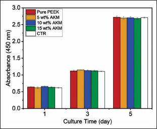
To test the biocompatibility of the composites, BMSC cells were cultured for 5 days on the composite tablets in the medium. A control group was set for comparison, in which BMSCs were cultured in a medium without additives. Figure 8 shows the results obtained by a CCK-8 assay. In all groups, the absorbance values increased with time, and there was no significant difference in absorbance among groups. This means that the composite materials have good cell proliferation and biocompatibility compared with PEEK material. The cells cultured for 1 day and 5 days were dyed and observed by confocal microscopy (Figure 9). In all groups, the cells were uniformly and densely attached to the composite surface. Compared with the first day, the cytoskeletons of the cells (schematized by red color) on the fifth day show obvious growth, which proves that the cells seeded on the tablets have a good growth condition. This indicates that the composites have positive effects on cell proliferation, which demonstrates good biocompatibility.
Figure 8.
BMSCs proliferation results of the composite tablets for 1, 3, and 5 days.
Figure 9.

Fluorescence microscope images of BMSCs cultured on the composite tablets for 1 day and 5 days.
For evaluating the bioactivity, the HT-LPBF-printed samples were soaked in the SBF for 7 days, and the hydroxyapatite formation on the surface was observed by the SEM (Figures 10 and 11). The pure PEEK sample exhibited a smooth surface without hydroxyapatite formation. Differently, white precipitates with different morphologies appeared on the composite samples (schematized by green color). The AKM content of the sample had a significant effect on the formation of apatite. On the surface of the 5 wt% AKM/PEEK composite, a few hydroxyapatite precipitates and aggregates were attached to the surface of the sample in small granular form. With the increase of AKM content, porous reticulated sediments were attached to the composite surface, and the covering density increased (Figure 10c, schematized by yellow circle). When the AKM content reached 15 wt%, the composite surface formed a synaptic morphology accompanied by a completely covered network surface and granular blocks (Figure 10d, schematized by green color and yellow circle). This proves that the AKMs in the PEEK matrix promote hydroxyapatite formation, which suggests that the bioactivity and osseointegration of samples are improved.
Figure 10.
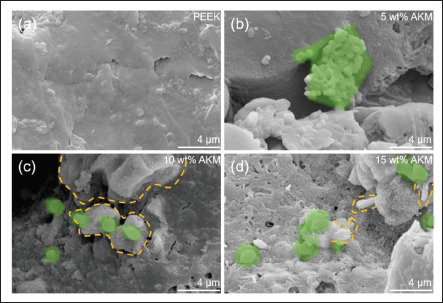
SEM images of the formation of hydroxyapatite on the sample surface after being soaked in SBF for 7 days. (a) PEEK, (b) 5 wt% AKM/PEEK, (c) 10 wt% AKM/PEEK, and (d) 15 wt% AKM/PEEK.
Figure 11.

Comparison of morphology evolution of deposited hydroxyapatite over time between PEEK and 15 wt% AKM/PEEK composite.
In addition, the improved biological activity of the composite could also be observed from the evolving morphology of hydroxyapatite over time (Figure 11). For pure PEEK, only a few microparticles adhered to the material surface with a time extension to 7 days, indicating weak bioactivity. By contrast, a large number of microparticles were attached to the surface of 15 wt% AKM/PEEK composite on the first day. It was accompanied by the formation of petal-like hydroxyapatite with a size of fewer than 2 μm. With the extension of time to the seventh day, the petal-like hydroxyapatite grew to a larger size exceeding 6 μm. This is mainly because the Si ions released by AKM in the SBF solution promoted the formation and growth of hydroxyapatite[48]. On the 14th day, the composite was covered with a dense network layer of hydroxyapatite. These results indicate that the biological activity of the material is greatly improved with the incorporation of AKM.
4. Conclusion
In this study, the AKM/PEEK composite powders in the weight ratio from 0 to 15 wt% were prepared, and the effects of AKM on mechanical and biological properties were investigated. The morphology, melting/ crystallization properties, and thermal stability of the composite powders were tested to evaluate the HT-LPBF processability. The results suggested that the tiny AKM particles are uniformly dispersed in the composite. The composition of AKM has little effect on the sintering window but can delay the peak crystallization temperature to reduce part warping. The melting enthalpy decreases with the increase of AKM content, which may lead to a higher surface temperature during the HT-LPBF process 155156and further decomposition of the material. The tensile strength and Young’s modulus are in the range of 30.83– 98.73 MPa and 2.27–3.71 GPa, respectively, which can match the mechanical properties of cancellous bone well. The change in mechanical properties is directly related to the decreased crystallinity. The cell culture experiments demonstrated the biocompatibility of the composites, which permits the good proliferation of BMSC cells. The dense network layer of hydroxyapatite and petallike hydroxyapatite could be found on the composite surface after in vitro mineralization, which proves that the AKM/PEEK composites have good bioactivity. The good mechanical properties and biological properties of the AKM/PEEK composite accentuate its application potential in the repair of cancellous bone defects.
Acknowledgments
The authors would like to thank the State Key Laboratory of Materials Processing and Die & Mould Technology and HUST Testing Center.
Funding
The study is supported by the National Natural Science Foundation of China (52105341), Key Research and Development Plan of Hubei Province (2021BAA211 and 2022BAA030), China Postdoctoral Science Foundation (2020M682406), China Electric Power Research Institute (PDB51201901707), Fundamental Research Funds for the Central Universities (2019kfyRCPY044 and 2021GCRC002), and Program for HUST Academic Frontier Youth Team (2018QYTD04).
Conflict of interest
The authors declare that they have no known competing financial interests or personal relationships that could have appeared to influence the work reported in this paper.
Author contributions
Conceptualization: Chunze Yan
Formal analysis: Jin Su
Funding acquisition: Peng Chen, Chunze Yan, Yusheng Shi
Investigation: Haoze Wang, Zixing Shu, Jiayi Hou
Methodology: Zhiyuan Chen
Project administration: Yusheng Shi
Supervision: Peng Chen, Chunze Yan, Yusheng Shi
Visualization: Zhaoqing Li
Writing – original draft: Zhiyuan Chen, Chunze Yan
Writing – reviewing & editing: Zhiyuan Chen, Peng Chen
Ethics approval and consent to participate
157Not applicable.
Consent for publication
Not applicable.
Availability of data
Data can be obtained from the corresponding author upon reasonable request.
References
- 1.Chen P, Wang H, Su J, et al. Recent advances on highperformance polyaryletherketone materials for additive manufacturing. Adv Mater. 2022;34(2200750):1–26. doi: 10.1002/adma.202200750. [DOI] [PubMed] [Google Scholar]
- 2.Chen J, Liu X, Tian Y, et al. 3D-printed anisotropic polymer materials for functional applications. Adv Mater, 2022;34(5):2102877. doi: 10.1002/adma.202102877. [DOI] [PubMed] [Google Scholar]
- 3.Wu H, Wang O, Tian Y, et al. Selective laser sinteringbased 4D printing of magnetism-responsive grippers. ACS Appl Mater Interfaces. 2021;13(11):12679–12688. doi: 10.1021/acsami.0c17429. [DOI] [PubMed] [Google Scholar]
- 4.Wu H, Zhang X, Ma Z, et al. A material combination concept to realize 4D printed products with newly emerging property/functionality. Adv Sci. 2020;7(9):1903208. doi: 10.1002/advs.201903208. [DOI] [PMC free article] [PubMed] [Google Scholar]
- 5.Feng P, Wu P, Gao C, et al. A multimaterial scaffold with tunable properties: Toward bone tissue repair, Adv Sci. 2018;5(6):1700817. doi: 10.1002/advs.201700817. [DOI] [PMC free article] [PubMed] [Google Scholar]
- 6.Berretta S, Evans K, Ghita O. Additive manufacture of PEEK cranial implants: Manufacturing considerations versus accuracy and mechanical performance. Mater Des. 2018;139:141–152. [Google Scholar]
- 7.Wu H, Wang Q, Wu Z, et al. Multi-material additively manufactured magnetoelectric architectures with a structure-dependent mechanical-to-electrical conversion capability. Small Methods. 2022;6(12):e2201127. doi: 10.1002/smtd.202201127. [DOI] [PubMed] [Google Scholar]
- 8.Chen P, Su J, Wang H, et al. Mechanical properties and microstructure characteristics of lattice-surfaced PEEK cage fabricated by high-temperature laser powder bed fusion. J Mater Sci Technol. 2022;125:105–117. [Google Scholar]
- 9.Chen B, Yazdani B, Benedetti L, et al. Fabrication of nanocomposite powders with a core-shell structure. Compos Sci Technol. 2019;170:116–127. [Google Scholar]
- 10.Shirazi SF, Gharehkhani S, Mehrali M, et al. A review on powder-based additive manufacturing for tissue engineering: Selective laser sintering and inkjet 3D printing. Sci Technol Adv Mater. 2015;16(3):033502. doi: 10.1088/1468-6996/16/3/033502. [DOI] [PMC free article] [PubMed] [Google Scholar]
- 11.Wang H, Chen P, Wu H, et al. Comparative evaluation of printability and compression properties of poly-ether- ether-ketone triply periodic minimal surface scaffolds fabricated by laser powder bed fusion. Addit Manuf. 2022;57:102961. [Google Scholar]
- 12.Yang L, Yan C, Han C, et al. Mechanical response of a triply periodic minimal surface cellular structures manufactured by selective laser melting. Int J Mech Sci. 2018;148:149–157. [Google Scholar]
- 13.Zhang C, Zheng H, Yang L, et al. Mechanical responses of sheet-based gyroid-type triply periodic minimal surface lattice structures fabricated using selective laser melting. Mater Des. 2022;214:110407. [Google Scholar]
- 14.Haleem A, Javaid M. Polyether ether ketone (PEEK) and its 3D printed implants applications in medical field: An overview. Clin Epidemiol Global Health. 2019;7(4):571–577. [Google Scholar]
- 15.Oladapo BI, Zahedi SA, Ismail SO, et al. 3D printing of PEEK and its composite to increase biointerfaces as a biomedical material: A review. Colloids Surf B Biointerfaces. 2021;203:111726. doi: 10.1016/j.colsurfb.2021.111726. [DOI] [PubMed] [Google Scholar]
- 16.Chen B, Berretta S, Evans K, et al. A primary study into graphene/polyether ether ketone (PEEK) nanocomposite for laser sintering. Appl Surf Sci. 2018;428:1018–1028. [Google Scholar]
- 17.Zhang S, Feng Z, Hu Y, et al. Endowing polyetheretherketone implants with osseointegration Properties: In situ construction of patterned nanorod arrays. Small. 2022;18(5):2105589. doi: 10.1002/smll.202105589. [DOI] [PubMed] [Google Scholar]
- 18.Yuan X, Ouyang L, Luo Y, et al. Multifunctional sulfonated polyetheretherketone coating with beta- defensin-14 for yielding durable and broad-spectrum antibacterial activity and osseointegration. Acta Biomater. 2019;86:323–337. doi: 10.1016/j.actbio.2019.01.016. [DOI] [PubMed] [Google Scholar]
- 19.Tan LJ, Zhu W, Zhou K. Recent progress on polymer materials for additive manufacturing. Adv Funct Mater. 2020;30(43):2003062. [Google Scholar]
- 20.Najeeb S, Zafar MS, Khurshid Z, et al. Applications of polyetheretherketone (PEEK) in oral implantology and prosthodontics. J Prosthodont Res. 2016;60(1):12–19. doi: 10.1016/j.jpor.2015.10.001. [DOI] [PubMed] [Google Scholar]
- 21.Brizuela A, Herrero-Climent M, Rios-Carrasco E, et al. Influence of the elastic modulus on the osseointegration of dental implants. Materials. 2019;12(6):980. doi: 10.3390/ma12060980. [DOI] [PMC free article] [PubMed] [Google Scholar]
- 22.Basgul C, Yu T, MacDonald DW, et al. 2020. Does annealing improve the interlayer adhesion and structural integrity of FFF 3D printed PEEK lumbar spinal cages? J Mech Behav Biomed Mater 102103455. [DOI] [PubMed] [Google Scholar]
- 23.Velasco-Hogan A, Xu J, Meyers MA. Additive manufacturing as a method to design and optimize bioinspired structures. Adv Mater. 2018;30(52):1800940. doi: 10.1002/adma.201800940. [DOI] [PubMed] [Google Scholar]
- 24.Chen B, Wang Y, Berretta S, et al. Poly aryl ether ketones (PAEKs) and carbon-reinforced PAEK powders for laser sintering. J Mater Sci. 2017;52(10):6004–6019. doi: 10.1007/s10853-017-0840-0. [DOI] [PMC free article] [PubMed] [Google Scholar]
- 25.Berretta S, Evans KE, Ghita O. Processability of PEEK a new polymer for high temperature laser sintering (HT-LS). Eur Polym J. 2015;68(Suppl C):243–266. [Google Scholar]
- 26.Berretta S, Evans KE, Ghita OR. Predicting processing parameters in high temperature laser sintering (HT-LS) from powder properties. Mater Des. 2016;105:301–314. [Google Scholar]
- 27.158Chen P, Cai H, Li Z, et al. Crystallization kinetics of polyetheretherketone during high temperature-selective laser sintering. Addit Manuf. 2020;36:101615. [Google Scholar]
- 28.Torstrick FB, Lin ASP, Potter D, et al. Porous PEEK improves the bone-implant interface compared to plasma- sprayed titanium coating on PEEK. Biomaterials. 2018;185:106–116. doi: 10.1016/j.biomaterials.2018.09.009. [DOI] [PubMed] [Google Scholar]
- 29.Almasi D, Iqbal N, Sadeghi M, et al. Preparation methods for improving PEEK’s bioactivity for orthopedic and dental application: A review. Int J Biomater. 2016;2016:8202653. doi: 10.1155/2016/8202653. [DOI] [PMC free article] [PubMed] [Google Scholar]
- 30.Ma R, Tang T. Current strategies to improve the bioactivity of PEEK. Int J Mol Sci. 2014;15(4):5426–5445. doi: 10.3390/ijms15045426. [DOI] [PMC free article] [PubMed] [Google Scholar]
- 31.Vaezi M, Black C, Gibbs DMR, et al. Characterization of new PEEK/HA composites with 3D HA network fabricated by extrusion freeforming. Molecules. 2016;21(6):687. doi: 10.3390/molecules21060687. [DOI] [PMC free article] [PubMed] [Google Scholar]
- 32.Von Wilmonsky C, Lutz R, Meisel U, et al. In vivo evaluation of ß-TCP containing 3D laser sintered poly(ether ether ketone) composites in pigs. J Bioact Compat Polym. 2009;24(2):169–184. [Google Scholar]
- 33.Ma R, Yu Z, Tang S, et al. Osseointegration of nanohydroxyapatite- or nano-calcium silicate-incorporated polyetheretherketone bioactive composites in vivo. Int J Nanomed. 2016;11:6023–6033. doi: 10.2147/IJN.S115286. [DOI] [PMC free article] [PubMed] [Google Scholar]
- 34.Wang H, Chen P, Shu Z, et al. Laser powder bed fusion of poly-ether-ether-ketone/bioactive glass composites: Processability, mechanical properties, and bioactivity. Compos Sci Technol. 2023;231:109805. [Google Scholar]
- 35.Yuan S, Shen F, Chua CK, et al. Polymeric composites for powder-based additive manufacturing: Materials and applications. Progr Polym Sci. 2019;91:141–168. [Google Scholar]
- 36.Mohammadi H, Baba Ismail YM, Bin Shariff KA, et al. Synthesis and characterization of Akermanite by mechanical milling and subsequent heat treatment. J Phys Conf Series. 2018;1082:012021. [Google Scholar]
- 37.Xu S, Lin K, Wang Z, et al. Reconstruction of calvarial defect of rabbits using porous calcium silicate bioactive ceramics. Biomaterials. 2008;29(17):2588–2596. doi: 10.1016/j.biomaterials.2008.03.013. [DOI] [PubMed] [Google Scholar]
- 38.Huang Y, Jin X, Zhang X, et al. In vitro and in vivo evaluation of akermanite bioceramics for bone regeneration. Biomaterials. 2009;30(28):5041–5048. doi: 10.1016/j.biomaterials.2009.05.077. [DOI] [PubMed] [Google Scholar]
- 39.Wu C, Chang J, Zhai W, et al. 2006. Porous akermanite scaffolds for bone tissue engineering: Preparation, characterization, and in vitro studies. J Biomed Mater Res Part B Appl Biomater 78B(1):47–55 [DOI] [PubMed] [Google Scholar]
- 40.Duman Ş, Bulut B. Effect of akermanite powders on mechanical properties and bioactivity of chitosan- based scaffolds produced by 3D-bioprinting. Ceram Int. 2021;47(10):13912–13921. [Google Scholar]
- 41.Zhai W, Lu H, Chen L, et al. Silicate bioceramics induce angiogenesis during bone regeneration. Acta Biomater. 2012;8(1):341–349. doi: 10.1016/j.actbio.2011.09.008. [DOI] [PubMed] [Google Scholar]
- 42.Chen P, Cai H, Li Z, et al. Crystallization kinetics of polyetheretherketone during high temperature-selective laser sintering. Addit Manuf. 2018;36:101615. [Google Scholar]
- 43.Chen P, Wu H, Zhu W, et al. Investigation into the processability, recyclability and crystalline structure of selective laser sintered Polyamide 6 in comparison with Polyamide 12. Polym Test. 2018;69:366–374. [Google Scholar]
- 44.Chen P, Su J, Wang H, et al. Aging mechanism of polyetheretherketone powder during layer-wise infrared radiation of high-temperature laser powder bed fusion. Mater Des. 2022;213:110348. [Google Scholar]
- 45.Zhu W, Yan C, Shi Y, et al. Investigation into mechanical and microstructural properties of polypropylene manufactured by selective laser sintering in comparison with injection molding counterparts. Mater Des. 2015;82:37–45. [Google Scholar]
- 46.Li Y, Liu C. Nanomaterial-based bone regeneration. Nanoscale. 2017;9(15):4862–4874. doi: 10.1039/c7nr00835j. [DOI] [PubMed] [Google Scholar]
- 47.Geetha M, Singh AK, Asokamani R, et al. Ti based biomaterials, the ultimate choice for orthopaedic implants—A review. Progr Mater Sci. 2009;54(3):397–425. [Google Scholar]
- 48.Su J, Hua S, Chen A, et al. Three-dimensional printing of gyroid-structured composite bioceramic scaffolds with tuneable degradability. Biomater Adv. 2022;133:112595. doi: 10.1016/j.msec.2021.112595. [DOI] [PubMed] [Google Scholar]
Associated Data
This section collects any data citations, data availability statements, or supplementary materials included in this article.
Data Availability Statement
Data can be obtained from the corresponding author upon reasonable request.