

Abstract
A passive add-on greatly multiplies the sweep rate of any mechanical scanner while also enhancing throughput, enabling a single linear scanner to produce ultrafast 1D or 2D laser scans for general applications.
An optical laser scanner [1] is an essential tool for a variety of applications including remote sensing, material processing, communication, projection display, profilometry, spectroscopy, and imaging. The most common is a mechanical scanner, such as a galvanometric, resonant, or polygonal scanner. Though low-cost and easy to use, these are fundamentally limited in both speed and throughput by inertia [1]. Inertia-free scanners such as electro-optic or acousto-optic deflectors (EODs, AODs) provide line-scan rates of hundreds of kilohertz, but only over small scan angles with a limited number of resolvable points per line sweep [2]. Moreover, for virtually all optical scanners, 2D scanning is achieved by using dual-axis scanners, where the frame rate can be further limited by the slow-axis scanner.
Here we describe a scan multiplier unit (SMU) that can be combined with any mechanical scanner for general high-speed high-throughput laser scanning applications. Using a passive rescan strategy, the device converts a single line scan from the scanner into multiple sequential line scans, leading to 1D scan patterns with scan rates and throughputs surpassing the physical inertia limit of the original scanner. The rescanned lines can also be configured to be non-overlapping, such that a single linear scanner sweep produces a raster scan over a 2D field-of-view (FOV) with a frame rate equal to the line-scan rate of the scanner. As an example, we demonstrate this strategy on a two-photon microscope where we achieve an ultrafast line-scan rate up to 592 kHz, or frame rate at 16 kHz.
In conventional mirror-based scanning, a laser beam is reflected off a tilting mirror (the scanner), causing the beam to sweep through a full scan angle Θ0 at a rate R0. The principle of a SMU is to doubly reflect this laser beam off the same scanner using a non-inverting unit-magnification imaging array. Here, this consists of a folded 8f imaging system made of a lens (focal length fr), a 1D N × 1 lenslet array of pitch p, and a retro-reflecting mirror [Fig. 1(a)]. If the lenslet array is aligned along the scanner scanning axis [x-axis, Fig. 1(b)], then by geometric optics every time the laser beam sweeps across an individual lenslet, the rescanned beam, upon double pass, scans across a new scan angle Θx = 2p/ fr. In the case of an imaging geometry, a scan lens (focal length fs) is introduced to convert angular beam scanning into spatial scanning of a focused spot, resulting in overlapping line scans of length FOVx = Θx fs. Thus, if the lenslet array is chosen such that Np = Θ0 fr, the SMU produces an ultrafast 1D scan pattern [Fig. 1(d)] with a multiplied scan rate Rx = NR0. Note that this scan-rate multiplication is entirely passive and does not require any modification to the operation of the scanner itself (it is inertia free), nor does it entail any additional restriction to the beam diameter D at the scanner.
Fig. 1.

(a) Schematic of SMU with a single-axis scanner. (b,d) 1D scanning. (c,e) 2D scanning. (f) 2D scanning with experimentally measured foci (Θ0 = 25°, N = 16).
To convert the above overlapping 1D scan into a 2D raster scan pattern, one need simply introduce an additional y-axis offset to the beam upon each rescan. This can be achieved by rotating the lenslet array by a small angle ϕ about the optical axis [Fig. 1(c)]. The SMU then converts each 1D scan from the original scanner into a multiplicity of scans in 2D, spanning in the y direction Θy = 2ϕ(N − 1)p/ fr, or FOVy = Θy fs [Fig. 1(e)]. The sweep rate of this entire 2D scan pattern is then Ry = R0, corresponding to the original scanner sweep rate.
An important parameter for evaluating scanner performance is its throughput, defined as the number of resolvable spots scanned per second. For a beam of wavelength λ, the focal spot size is given by λfs/D. If the throughput of the original scanner is Q0 = R0Θ0D/λ, then upon rescan, because D remains the same, we find that Qx = RxΘxD/λ = 2Q0. In other words, the scanning throughput, contrary to the general tendency of being reduced at higher speeds for mechanical scanners, becomes doubled here (ideally) and surpasses the inertia limit as well.
We constructed a SMU using a fr = 54 mm lens (Thorlabs LSM54–850), and a 16 × 1 lenslet array (Amus GmbH; f = 3.98 mm, p = 1.5 mm). At ϕ = 0.61°, we measured the rescanned foci (Coherent Chameleon Ultra at 920 nm; D = 3.6 mm, fs = 150 mm) using a galvanometric scanner (Cambridge Tech. 6215H) across a 25° scan angle [Fig. 1(f)]. Because of beam clipping due to the smaller clear aperture size of the individual lenslets, the foci are degraded toward the edges of the FOV leading to a smaller throughput than ideal. Nevertheless, the measured throughput per scanner sweep was 2.73 k spots, as compared to 1.71 k spots without the SMU. The actual FOV without beam clipping was 5.56 × 1.32 mm [red square in Fig. 1(f)].
With a R0 = 16 kHz resonant scanner (Cambridge Tech. CRS 8 kHz, Θ0 = 26°), we integrated this SMU into a two-photon microscope, thus achieving an average scan rate of 256 kHz, which is beyond the limit of any existing mechanical scanners. At ϕ = 0° (1D scan), the time resolved signal obtained by scanning a 10 μm fluorescent bead is shown in Fig. 2(a). 16 peaks are observed within a single 62.5 μs scanner sweep, confirming a 16× multiplication of the line scan rate. The nonuniform spacing of the peak signals, caused by the sinusoidal speed of the resonant mirror, can be corrected numerically [Fig. 2(b)] or, alternatively, by using a linear-speed polygonal scanner instead.
Fig. 2.

(a,b) Time resolved signal of a 10 μm fluorescent bead scanned at 256 kHz line rate. (c,d) 16 kHz imaging of flowing fluorescent beads at different speeds. Image shearing is observed at higher flow speed due to bead motion and bidirectional scanning. (e-g) In vivo Ca2+ imaging at 16 kHz: (e) single frame; (f) average frame of 6 active neurons; (g) corresponding Ca2+ traces over three 1-minute recordings.
To demonstrate the capacity of a SMU to enable ultrafast 2D imaging, we monitored the flow of 10 μm fluorescent beads through a glass capillary [Fig. 2(c,d) and Visualization 1,2] and in vivo Ca2+ dynamics in a GCamP6 labelled mouse brain at 220 μm depth [Fig. 2(e–g)], both at 16 kHz frame rates. In the latter case we switched to a 37 × 1 lenslet array (Amus GmbH; f = 2.25 mm, p = 0.68 mm, ϕ = 0.85°) to obtain increased y-axis sampling, achieving an equivalent line rate of 592 kHz. Importantly, here the laser power remains focused onto a single spot rather than being subdivided into many foci, making it advantageous for deep tissue imaging. To our knowledge, this is the fastest point-scanning two-photon microscope ever reported.
Finally, in Fig. 3, we compare the performance of commercially available scanners when upgraded with a SMU add-on. In general, mechanical scanners are limited to line-scan rates below ~100 kHz because of inertia. Although polygonal scanners in principle can surpass this limit by increasing facet numbers, this comes at the cost of proportionally reduced throughput due to smaller facet size (hence smaller D). By combining a SMU with a conventional medium-speed high-throughput scanner, ~1 MHz scan rates become possible. This is comparable to an inertia-free AOD but with a larger number of resolvable points per sweep, thus better suited for applications that require both high-speed and high-resolution. Additionally, since the SMU is largely achromatic, it requires no compensation for spatial dispersion or cylindrical lens effects.
Fig. 3.
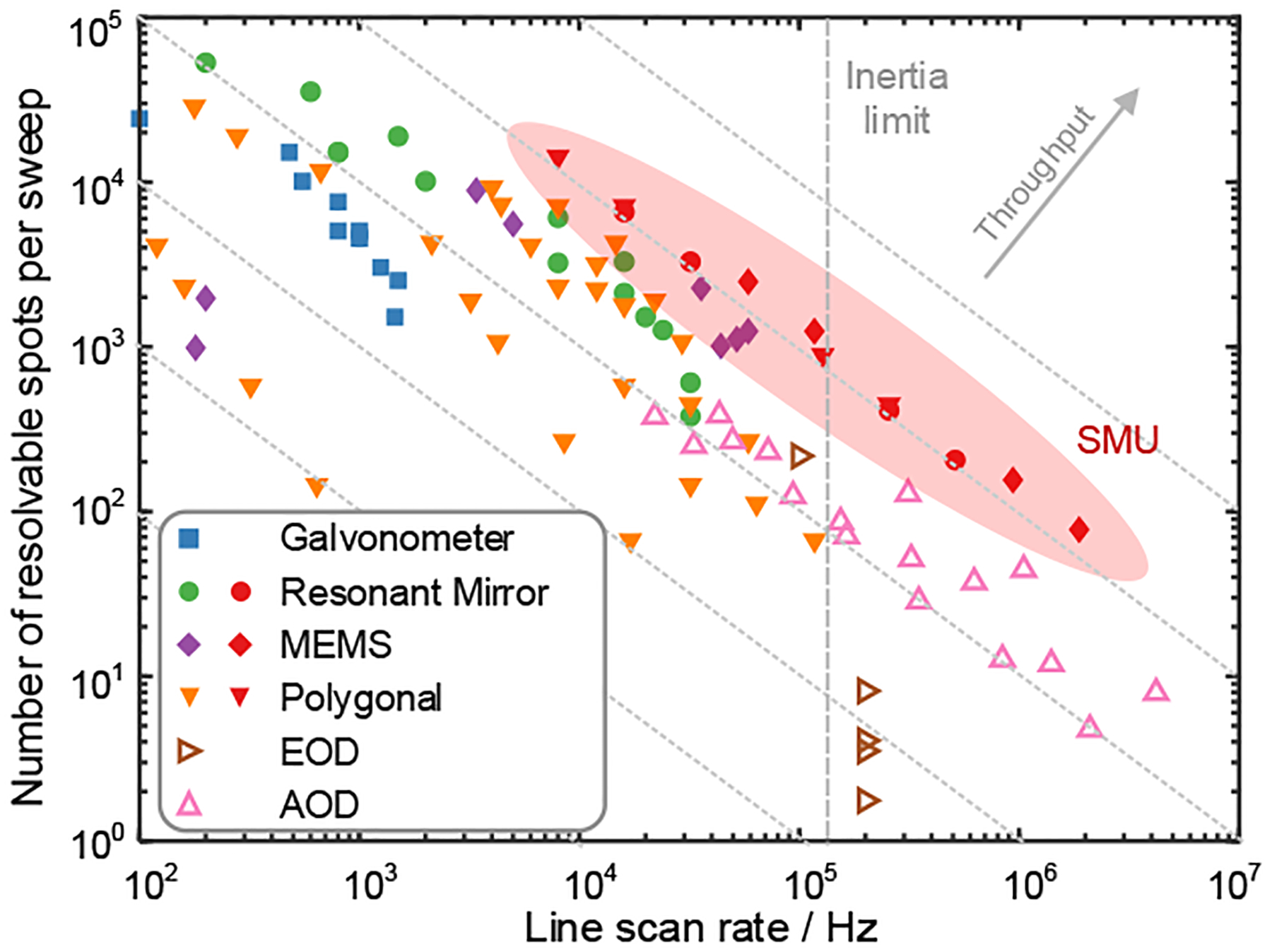
Comparison of commercially available optical scanners without and with SMU add-on. Solid markers, inertial scanners. Empty markers, inertia-free scanners. Red solid markers, corresponding scanners with SMU add-on for N ∈ [1, 32]. Data points for SMU based on Cambridge Tech. CRS 8 kHz, PHCAB, and Hamamatsu Corp. S13989–01H.
More recently, techniques employing passive pulse splitting [3, 4] or spatial dispersion [5, 6] have demonstrated line-scan rates > 10 MHz. However, the requirement of pulsed or chirped lasers, the resultant laser power reduction per focus, and the spatially dependent spectra/intensity of the foci, limit their applicability. In contrast, a SMU is fundamentally based on mechanical mirror scanners and thus requires no specialized sources, making it useful for a much wider range of applications.
In summary, we have described a simple add-on SMU made entirely of passive components that can multiply the scan rate of any mechanical scanner far beyond its inertia limit while also converting 1D scans to 2D with enhanced throughput. Though we demonstrated this technique with two-photon microscopy, it is general and can be useful for any applications that require high-speed high-throughput laser scanning.
Funding.
National Institutes of Health R01NS116139.
Footnotes
Disclosures. Provisional patent application No. 63/222,031.
Data Availability Statement.
Data available upon request.
FULLREFERENCES
- 1.Marshall GF and Stutz GE, Handbook of optical and laser scanning (Taylor & Francis, 2012). [Google Scholar]
- 2.Römera G and Bechtoldb P, “Electro-optic and acousto-optic laser beam scanners,” Phys. Procedia 56, 29–39 (2014). [Google Scholar]
- 3.Wu J-L, Xu Y-Q, Xu J-J, Wei X-M, Chan AC, Tang AH, Lau AK, Chung BM, Shum HC, Lam EY et al. , “Ultrafast laser-scanning time-stretch imaging at visible wavelengths,” Light. Sci. & Appl 6, e16196–e16196 (2017). [DOI] [PMC free article] [PubMed] [Google Scholar]
- 4.Beaulieu DR, Davison IG, Kılıç K, Bifano TG, and Mertz J, “Simultaneous multiplane imaging with reverberation two-photon microscopy,” Nat. Methods 17, 283–286 (2020). [DOI] [PMC free article] [PubMed] [Google Scholar]
- 5.Goda K, Mahjoubfar A, Wang C, Fard A, Adam J, Gossett DR, Ayazi A, Sollier E, Malik O, Chen E et al. , “Hybrid dispersion laser scanner,” Sci. Reports 2, 1–8 (2012). [DOI] [PMC free article] [PubMed] [Google Scholar]
- 6.Karpf S, Riche CT, Di Carlo D, Goel A, Zeiger WA, Suresh A, Portera-Cailliau C, and Jalali B, “Spectro-temporal encoded multiphoton microscopy and fluorescence lifetime imaging at kilohertz frame-rates,” Nat. Commun 11, 1–9 (2020). [DOI] [PMC free article] [PubMed] [Google Scholar]
Associated Data
This section collects any data citations, data availability statements, or supplementary materials included in this article.
Data Availability Statement
Data available upon request.