

Summary
The fuel cell’s three layers—anode/electrolyte/cathode—convert fuel’s chemical energy into electricity. Electrolyte membranes determine fuel cell types. Solid-state and ceramic electrolyte SOFC/PCFC and polymer based PEMFC fuel cells dominate fuel cell research. We present a new fuel cell concept using next-generation ceramic nanocomposites made of semiconductor-ionic material combinations. A built-in electric field driving mechanism boosts ionic (O2− or H+ or both) conductivity in these materials. In a fuel cell device, non-doped ceria or its heterostructure might attain 1 Wcm−2 power density. We reviewed promising functional nanocomposites for that range. Ceria-based and multifunctional semiconductor-ionic electrolytes will be highlighted. Owing to their simplicity and abundant resources, these materials might be used to make fuel cells cheaper and more accessible.
Subject areas: Electrochemical materials science, Energy engineering, Materials property
Graphical abstract
Electrochemical materials science; Energy engineering; Materials property
Introduction
The principle of a fuel cell was introduced by Sir William Grove already in 1839 who showed that an electric current could be produced from an electrochemical reaction between hydrogen and oxygen over a coupled catalyst electrode1 shown in the historical Figure 1.
Figure 1.

Sketch of William Grove’s 1839 fuel cell
Grove’s 1839 gas voltaic battery diagram. (From Proceedings of the Royal Society) [1] Redrawn with permission of Taylor & Francis Journal.
The fuel cell (FC) development since Grove’s invention has followed the same kind of structural design in which the FC composes of three functional components: The anode, electrolyte, and cathode, which is also called the membrane electrode assembly (MEA).2,3 The core component of the fuel cell is the electrolyte which also defines the type of the fuel cell and its operational temperatures. Accordingly, the most common fuel cell types are the solid oxide fuel cell (SOFC), proton ceramic fuel cell (PCFC), molten carbonate fuel cell (MCFC), phosphorus acid fuel cell (PAFC), polymer electrolyte membrane fuel cell (PEMFC), and alkaline fuel cell (AFC) also shown in Figure 2. Their operational temperatures are as follows: SOFC: 800–1000°C, PCFC: 600–800°C, MCFC: 600–650°C, PAFC: 120–220°C; PEMFC: 20–220°C and AFC: 20–120°C.4,5,6 Good fuel cell efficiency can be reached without noble metal catalysts at a high temperature, e.g., 600–1000°C. This would be necessary for low-temperature fuel cells (<300°C) to achieve good performance.
Figure 2.

Classification of fuel cells by the electrolyte
Owing to the electrolytes' properties, the temperature range between 300-600°C is not well covered. The temperature levels shown here represent typical electrolyte materials and ionic conductivities to deliver sufficiently high-power density. Advanced thin-film manufacturing technologies for SOFC or PCFC enable making thinner electrolytes with lower resistance, thus reducing the fuel cell operating temperatures well below those above, e.g., in PCFC to 500°C.7,8
In addition, each fuel cell type employs a specific variety of ions in the transport process in the electrolyte: SOFC (O2−), MCFC (CO3=), AFC (OH−), and protons in PCFC, PAFC, and PEMFC as demonstrated in Figure 2.
Targeting the 300–600°C temperature range for fuel cell operation would require seeking electrolytes beyond the traditional sphere. Still, oxygen-ion conductors could be relevant in this context.9 Figure 3 shows a range of oxide materials of interest that could potentially replace the conventional high-temperature yttria-stabilized zirconia (YSZ) electrolyte used in SOFC10,11,12,13,14,15 but still missing a high enough ionic conductivity (>0.1 S/cm) at a temperature below 600°C. Proton-conducting ceramic electrolytes BaZrO3 and BaCeO3 have recently been identified as promising materials for PCFC,16,17,18 their ionic conductivities remain at 10−3-10−2 S/cm only at 600°C.15
Figure 3.

Oxide-ion conductor candidates for SOFCs and PCFCs.15
Modified from15 with permission Elsevier.
More radical approaches may be necessary to challenge the 300–600°C operational range. Here we review novel functional nanocomposites that show a high promise for that range. The focus will be on ceria-based and multifunctional semiconductor-ionic electrolytes.
Ceria-based composites and nanocomposites as alternative electrolyte materials
Cation-doped cerium oxide, especially samarium doped ceria (SDC) and gadolinium doped ceria (GDC) have a fluoride structure, extensively studied as O2− conducting electrolyte in SOFC.19 However, there are some crucial problems with doped ceria. Firstly, to reach a high 0.1 S/cm oxygen ion conductivity, a temperature of 800°C is still required. At 600°C, doped ceria show only 10−3 – 10−2 S/cm.20,21 Secondly, Ce4+ in ceria may reduce to Ce3+ in the reducing fuel cell leading to significant electronic conduction, causing electrochemical and a lower open-circuit voltage (OCV).22 Also, the considerable size difference between Ce4+ (87p.m.) and Ce3+ (102p.m.) may cause some micro-cracking in the fuel cell operations leading to device failure.23
To solve these problems, improved ceria-based composites and nanocomposites have been developed, e.g., ceria-carbonate composites, successfully demonstrated at 300–600°C in low-temperature (LT) SOFC.24,25,26,27,28,29,30,31,32,33,34,35,36,37In ceria-carbonate composites, the ionic conductivity is enhanced by the composite melting effects, where the molten carbonate provides a solid-liquid interface resulting in high ionic transport. The interfacial regions between the two phases cause a combined effect, i.e., each constituent phase has high ionic conduction. Fabricating two- or multi-phase composites thus produces more interface regions, i.e., a kind of ionic conduction highway. Various ceria-salt composites (e.g., metal chlorites, metal hydrates, carbonates, and sulfates) have been investigated, where ceria-carbonate, such as samarium doped ceria (SDC), gadolinium doped ceria (GDC), yttrium doped ceria (YDC), Ca/Sm-co-doped CeO2 (CSDC), etc., composites have been combined with various metal carbonates, MxCO3 (M+ Li, Na, K, Ca, Ba, Sr, x = 1, 2) in single, Na, binary, Li-Na, Li-K, Na-K and ternary Li-Na-K, etc. systems [8–45].31,38,39,40,41,42,43,44,45,46,47,48,49,50,51,52,53,54,55,56,57,58,59,60,61,62,63 These ceria-carbonate composite systems have been used as electrolytes to demonstrate successful LT-SOFC operation. Ceria-carbonate composites have also shown excellent thermal and electrochemical stability,28,59,60 even standing long 6000-h tests.61
Most of these ceria-composites have not employed nanocomposite methodologies to make more controllable material microstructures and properties to improve the reproducibility and stability of the electrolyte. Nano effects have enhanced material grain boundary or surface ionic conduction, particularly in ceria and zirconia-based materials.64 However, at high temperatures (600–800°C), nano effects may be lost, and in ceria-based materials, the nano-effects may also increase the electronic conduction. It has been proposed to introduce a second-phase material to build up a heterostructure that could effectively block nanoparticle growth and significantly enhance ionic conductivity by modulating interfacial structures.63
The principal differences between the ceria-carbonate composites and nanocomposites are in the morphology shown in Figure 4 and the material properties and functionality. Figures 5A–5D shows that standard ceria-carbonate composites are irregular sharps of two-phase particles. Most of them reach a percolative mixture threshold in which two phases can form percolative paths along interface regions to maintain the combined effect, i.e., ionic conduction through the interfaces between the two-phase areas of the materials. This can only be possible when the carbonate melts. Figure 5F shows an intensive endothermic peak at about 497°C in the DTA curves, related to the melting of 53 mol%Li2CO3:47 mol%Na2CO3 carbonate eutectic. The conductivity leap occurs at the carbonate melting point to the molten phase in Figure 5E.33,57,64
Figure 4.

Illustration of the nanocomposite approach
Figure 5.

Ceria carbonate composites and electrical properties of SDC/NCO
SEM images of SDC-(53 mol% Li2CO3: 47 mol% Na2CO3) composites with carbonate content of (A) 10 wt %, (B) 20 wt %, (C) 30 wt %, and (D) 35 wt %,64 (E) conductivities' of composites with various carbonate contenet based on temperature dependence; (F) correspondingly, the DTA curves for SDC-(53 mol% Li2CO3:47 mol% Na2CO3) composites with various carbonate contents conductivities' temperature dependence64 with permission of Elsevier.
The particles are homogeneous for the nanocomposite, e.g., SDC-Na2CO3, as shown in Figure 6A. In the HRTEM images in Figure 6B, there is a clear core-shell structure with very thin (a few nm) shells of sodium carbonate covering the SDC nanoparticles. The composite can still form continuous interfacial regions to build fast ionic conducting channels along the SDC particle surfaces or two phases of SDC and Na2CO3 interfaces. The nanocomposite approach has successfully been employed to develop novel functional ceria-based nanocomposite materials, e.g., core-shell samarium doped ceria (SDC)-sodium carbonate.64,65 The most crucial difference between ceria-carbonate composites and nanocomposites relates to the carbonate maintaining its physical property. Reaching the carbonate melting point leading to high ionic conductivity requires at least a 20% carbonate share, which also causes corrosion with molten carbonates.65 Binary or trinary complex carbonate systems could be used to maintain the stability of ceria-carbonate composite electrolytes for use in LT-SOFC at temperatures below 600°C. In the SDC-Na2CO3 core-shell nanocomposite, the Na2CO3 does not keep its property. There is a phase transition already at around 300°C, much lower than the Na2CO3 melting point (851°C).40 In this case, the nanocomposite well maintains a solid phase property avoiding the molten carbonate corrosion problem. More importantly, the ceria-carbonate nanocomposite exhibits novel properties in the solid mechanical phase and superionic conduction, which is more advanced than in a regular ceria-carbonate composite.65 Figure 6D shows that a superionic transition occurs in the Na2CO3@SDC nanocomposite so that the ionic conductivity is well above 0.1 S/cm in the temperature range of 300–550°C. In the DSC thermal analysis, an endothermic peak is found in Figure 6E indicates a microstructure ordering change because the material’s two phases are maintained and melting does not occur.39
Figure 6.

Morphology, electrical and electrochemical properties of nanocomposites
(A) SEM image, (B) HRTEM image, (C) DSC curve, and (D) dependence of the conductivity vs. temperature of as-prepared SDC/Na2CO3 nanocomposite, (E–H) HR-TEM images and fuel cell performance and comparison of NSDC Copyright65,66 with permission of elsewhere.
The novel core-shell amorphous SDC/Na2CO3 nanocomposite in Figure 6B has a particle size of less than 100 nm. The thickness of the amorphous Na2CO3 shell is 4–6 nm forming a solid type of nanocomposite that displays high ionic conductivity over 0.1 S/cm above 300°C. Amorphous Na2CO3 and core-shell structure may play an essential role in the ionic conductivity attributed to the interface and interfacial conduction mechanism. In addition, Fan et al. have presented the practical synthesis of element/phase well-distributed, interfacial strongly linked Sm0.2Ce0.8O2-Na2CO3 (NSDC) nanocomposite with varied residual carbonate contents by an in situ one-pot one-step citric acid-nitrate combustion process. NSDC has increased ionic conductivity over conventionally prepared materials. NSDC9010 nanocomposite proton conductivity is 0.044 S/cm at 650°C. Electrolyte-supported SOFCs based on NSDC9010 nanocomposite electrolyte produce 281.5 mW cm2 at 600°C with LiNiO2 symmetric electro-catalysts. The unique core-shell structure, good phase distribution, and high interfacial area created by the one-step fabrication approach and the strong coupling between oxide and carbonate contribute to the superior ionic conductivity and fuel cell performance.66 The HR-TEM images of NSDC and fuel cell performance of NSDC9010 and comparison of fuel cell performance between the NSDC9010 and NSDC9505, NSDC8515 are shown in Figures 6E–6H. The ceria-carbonate in composite (molten-solid) or nanocomposite (solid-solid) interface may present a new approach to designing and developing superionic conductors for low-temperature SOFCs. Creating a ‘superionic highway’ interface in two-phase materials based on the coated ceria-carbonate composites has demonstrated a new way to realize SOFC/PCFC at 300–600°C.
Figure 7A illustrates a structural schematic diagram of the GDC-Na2CO3 fuel cell.67 Symmetrical electrodes Ni0.8Co0.15Al0.05LiO2-δ (NCAL) were used for redox functionality, whereas GDC-Na2CO3 works as an electrolyte to conduct the ions. Figure 7B shows the conduction path of protons and oxide ions through the electrolyte to accomplish the fuel cell reactions. Furthermore, the morphology of NCAL reveals the fluffy and well-porous structure assists in mass transfer with the extension of the triple-phase boundary depicted in Figure 7C. At the same time, GDC-Na2CO3 seems too dense without pores after sintering at 575 C, and the desired density assists in separating the H2 and air gases or prevents the contact between air and H2, as illustrated in Figure 7D. The XRD of GDC and GDC-Na2CO3 reveal a pure fluorite structure. Still, with the addition of Na2CO3, the peak intensity is lower, and slight expansion is noticed, confirming the formation of a GDC-Na2CO3 structure without impurity peaks, as demonstrated in Figure 7E.22,67 During the fuel cell operation, it is known that Na2CO3 changes into a molten state and makes connections or bonds with other materials, as seen in the examples with SDC-Na2CO3, GDC-Na2CO3, etc., to attain nanocomposite material characteristics.67 The relationship between the functions of the different particles as quick ions transport channels simultaneously speeds up the process leading to enhanced electrochemical fuel cell performance with a power density of 800 mW/cm2 at 575 C shown in Figure 7F. Moreover, several studies have been reported to enhance the ionic conduction and boost the fuel cell performance using the above stated phenomena.37,45,62,67,68,69
Figure 7.

Conduction path for protons and ions along with morphology, stuctural and electrochemical properties of GDC/NCO
(A and B) Schematic diagram of fuel cell device with GDC-Na2CO3 electrolyte and NCAL electrode along with the conduction path of protons and oxide ions, (C and D) SEM image of NCAL porous electrode and electrolyte membrane GDC-Na2CO3, (E and F) XRD analysis of GDC, GDC-Na2CO3, and performance of GDC-Na2CO3 electrolyte membrane67 with permission of John Wiley and Sons.
Recently it has been reported that pure ceria (CeO2) has shown fast ion transportation through surface conduction which is different from the traditional concept of doping ceria.70 Xing et al. designed a non-stoichiometry CeO2-δ forming CeO2@CeO2-δ core-shell structure to build up a fast proton shuttle on the surface layer, as shown in Figures 8A and 8B. It exhibited excellent proton conductivity at 0.16 S/cm and 697 mW/cm2 at 520°C as depicted in Figures 8C and 8D.71
Figure 8.

Proton shuttle mechnism and electrical & electrochemical properties of non-doped ceria
(A–D) Non-doping CeO2 with a non-stichometry CeO2-δ shell forming the core-shell structure resulting in high performance and fast proton conduction taken from71 permission with ACS.
Xia et al. synthesized non-doped CeO2 through the co-precipitation technique using different precipitating agents (Na2CO3, NH4HCO3, and KOH). The best performance was achieved using Na2CO3 as a precipitating agent, suggesting that Na2CO3 is a powerful agent in building strong bondage and long-lasting channels for quick ion transportation and enhancing the device performance.72 The designed fuel cell device based on the CeO2-Na2CO3 delivered 706 mW/cm2 at 550°C.72 The high performance is because of the morphological effect confirmed in the HAADAF-STEM image and cross-bonding mapping of each element, including Na, Ce, and O, as depicted in Figures 9A and 9B. Furthermore, one CeO2 particle was selected for morphology analysis, where it seems to be covered with an amorphous layer of Na2CO3 shown in Figures 9C and 9D. The TEM images confirm that the CeO2 is covered with a thin coating layer of Na2CO3 where the thickness of the coating layer was 3 nm with a lattice spacing of 0.19 nm related to the 220 planes of CeO2 as depicted in Figures 9E and 9F. Figure 9G shows the schematic diagram of the fuel cell based on the CeO2 electrolyte and the CeO2 particles covered with a thin layer to function as a core-shell structure that also prevents the CeO2 from reducing, which is a major issue with pure CeO2.70,71,73 Fan et al. use a self-doping approach to prepare a core-shell nanocomposite of CeO2 and alkali carbonates (Li2CO3, Na2CO3, and K2CO3) At 550°C in air, a remarkable ionic conductivity of 0.34 S/cm was formed, unlike the insulating CeO2 phase. The single-cell electrochemical performance reached 910 mW/cm2.74 All the above literature shows that the carbonates and the combined effect with doped and non-doped CeO2 are very favorable in enhancing the device performance. The high ionic conductivity achieved also paves the way to develop a new electrolyte for SOFC/PCFC at lower temperatures than the traditional ones.
Figure 9.

Morophology and mechnism of ions transport using surface layer in non-doped Ceria
(A and B) HAADAF-STEM image and elemental mapping of CeO2-Na2CO3 particles (C and D) HAADAF-STEM and elemental mapping along with elemental composition atomic fraction and mass fraction of CeO2-Na2CO3, (E–G) HR-TEM images of CeO2-Na2CO3 and Fuel cell diagram with a zoomed-in view of CeO2 particle coated with Na2CO3 layer72 with permission of Elsevier.
Besides the electrolyte ionic conduction, the redox process is equally crucial for constructing the composite electrolyte and electrodes. Ceria-based electrolytes have been frequently used as a catalyst because of their excellent redox properties originating from the reduction of Ce+4 to Ce+3 oxidation state.31 Two oxides with good redox properties have often been combined: For example, MCeO2, where M could be Gd, Sm, Ca, Mn, Pr, Y, and many more, plus MxOy structure in which M could be Bi, Co, Ti, Ni, and V whereas x and y can be in the range of 1–3 and 1–4, respectively.31
In the Ce-structure, incorporating the second phase, such as an electron acceptor phase, efficiently receives electrons to work as a redox agent. The two-phase composite material can turn into an efficient pure ionic conducting electrolyte material in comparison to pure CeO2, as depicted in Figure 10. The exact mechanism is probably applicable to construct composite electrodes, which can be accomplished using several nano-redox catalyst particles such as NiO distributed and coated with ceria shown in Figures 10A and 10B.31,75,76,77,78 Table 1 shows different composite electrolytes using ceria-based composites and their performance at different temperatures.
Figure 10.

Redox design of composite electrolyte
Redox design by using second-phase materials acting as an agent for electron acceptor and donor for composite electrolyte (A) and electrode (B)31 with permission of Elsevier.
Table 1.
Ceria-based composite electrolyte materials for fuel cells
| Nr | Ceria-carbonates | Gases | Conductivity (S/cm) | Power density (W/cm2) | Operating temperature (oC) | Reference |
|---|---|---|---|---|---|---|
| [1] | GDC-salt composites | H2/Air | 0.01–1 | 0.20–0.8 | 400–660 | Zhu et al.79 |
| [2] | YDC-22 wt % LiNaCO3 | H2/Air | 0.01–0.78 | 0.20–0.70 | 400–660 | Zhu et al.79 |
| [3] | GYDC-40 wt % LiKCO3 | H2/Air | – | 0.07–0.30 | 480–530 | Zhu et al.79 |
| [4] | SDC-10 wt % LiNaCO3 | H2/Air | 0.001–0.03 | 0.43 | 400–625 | Huang et al.64 |
| [5] | SDC-20 wt % LiNaCO3 | H2/Air | 0.003–0.09 | 0.94 | 400–625 | Huang et al.64 |
| [6] | SDC-30 wt % LiNaCO3 | H2/Air | 0.003–0.1 | 0.89 | 400–625 | Huang et al.64 |
| [7] | SDC-35 wt % LiNaCO3 | H2/Air | 0.1–0.15 | 1.08 | 400–625 | Huang et al.64 |
| [8] | SDC-30 wt % LiNaCO3 | H2/Air | 0.01–0.2 | 0.2–1.0 | 500–650 | Huang et al.80 |
| [9] | SDC-30 wt % LiNaKCO3 | H2/Air | 0.05–0.2 | 0.1–0.76 | 500–700 | Xia et al.58 |
| [10] | SDC-30 wt % LiNaCO3 | H2/(CO2/O2) | 0.05–0.16 | 0.3–1.70 | 500–650 | Xia et al.58 |
| [11] | GDC-30 wt % LiKCO3 | H2/Air | 0.002–0.09 | – | 300–700 | Benamira et al.81 |
| [12] | CeO2-nanocomposite | H2/Air | – | 0.20–0.70 | 450–580 | Raza et al.82 |
| [13] | SDC-Na2CO3 nanocomposite | H2/Air | – | 0.50–0.90 | 450–580 | Wang et al.65 |
| [14] | GYDC-LiNaCO3 | H2/Air | 0.2 | 0.6 | 550 | Zhang et al.83 |
Multifunctional semiconductor-ionic nanocomposites
To illustrate the concept of multifunctional electrolyte materials, Figure 11 shows a metal oxide semiconductor (MOS) of LiZnOx (or ½ Li2O–ZnO) with an ionic material SDC.82,84 Figure 11A displays the HRTEM image of LiZnOx-SDC nanocomposite where the nano-SDC particle as a core covered by a thin layer of LiZnOx.
Figure 11.

Morphology and electrical feature of SDC/LZO
(A) A high-resolution TEM image showing a core-shell structure of an SDC nanoparticle covered by a thin layer of LiZnOx; (B) simulated HRTEM image of ZnO coating at [2 1 0] projection.
(C) The dependence of the conductivity of non-coated SDC and LiZn-oxide coated SDC on the temperature in comparison with the conductivity curve of 1/2Li2O–ZnO cited from literature reported by Tsukamoto et al.84 with permission Elsevier.
ZnO is an n-type semiconductor and can react with Li2O to form ½ Li2O–ZnO or a LiZnOx compound. In LiZnOx-SDC semiconductor nanocomposite, the LiZnOx is coated on the SDC nanoparticles (less than 100 nm), forming a two-phase core-shell heterostructure (see HRTEM, Figures 11A and 11B). This particular core-shell microstructure can significantly enhance ionic conductivity reaching >0.1 S cm−1 at ca. 300°C, which is equivalent to pure SDC at 800°C or YSZ at 1000°C, as depicted in Figure 11C. A conventional single-phase structure cannot achieve such an enhancement—the ionic conductivity benefits here, particularly from interfacial effects.
Figure 12.

The electrical properties of YSZ/STO and 3D view of the interface of YSZ/STO
(A) The real part of the lateral electrical conductivity versus frequency of the tri-layer with 1-nm thick YSZ in the 357 to 531 K range. The uncertainty of conductance measurements is 1 n-S (10−2 S/cm in conductivity for the sample shown, see error bar)(Inset) Imaginary versus real part of the impedance (Nyquist) plots at 492, 511, and 531 K.
(B) Dependence of the ionic conductivity of the trilayers STO/YSZ/STO versus inverse temperature. The thickness range of the YSZ layer is 1–62 nm. (Top inset) 400 K conductance of [YSZ1nm/STO10 nm] (ni/2) superlattices as a function of the number of interfaces. (Bottom inset) Dependence of the conductance of [STO10nm/YSZ Xnm/STO10nm] trilayers at 500 K on YSZ layer thickness. Error bars are according to a 1 nS uncertainty of the conductance measurement.
(C) A 3D view of the interface, with the ionic radius reduced by half, to better visualize the plane of oxygen vacancies introduced in the interface. The square symbol in the legend indicates the empty positions available for oxygen ions at interface.85 Copyright permission from Science.
Another type of semiconductor-ionic heterostructure is found in the yttria-stabilized zirconia (YSZ)/strontium titanate SrTiO3 (STO)-YSZ thin-film composite system.85 The YSZ is a typical ionic conductor used in the traditional SOFC. STO is a standard semiconductor, which, together with YSZ, thus forms a semiconductor-ionic system. This system has shown several orders of magnitude higher ionic conductivity enhancement than the pure YSZ.85 The heterostructures where YSZ layers in the nanometer range (i-62 nm) and were fabricated between two 10 nm thick SrTiO3 (STO) layers. Figure 12 shows the electrical properties of the 1 nm-YSZ layer.
The STO-YSZ epitaxial heterostructure system can show up to eight orders of magnitude enhancement near room temperature.85 Enhancing the ionic conductivity and a YSZ layer thickness–independent conductivity implies an interface process. This may be because of the atomic reconstruction at the interface between highly different structures between the fluorite YSZ and perovskite STO, yielding colossal ionic conductivity values, where the interfaces play a significant role in enhancing the ionic conductivity massively. The coherent interface between very different structures can also significantly decrease the activation energy, thus greatly improving ionic mobility and increasing conductivity.85 This result is of paramount technological importance to achieving high O2− conduction at low temperatures.
The STO-YSZ system may have three parallel conduction paths from the interfaces and the bulk YSZ and STO layers. However, the bulk conductivity of YSZ is only 10−7 S/cm at 500°C. On the other hand, the reported conductivity values of the STO thin films are also much lower than those obtained with high conductance. Therefore, bulk YSZ or STO contributions can be ruled out, and an interface conduction mechanism is suggested instead. In addition, there is an abrupt conductivity decrease when the thickness changes from 30 to 62 nm. This may indicate a loss of interface structure when the YSZ layers exceed the critical thickness that the bulk behavior turns to effect.85 Further improvement of microstructural characterization (effective interfacial area and percolative pathways), explaining the interfacial conditions, and effective ionic transport and charge transfer under different working conditions are still required to understand the fundamental aspects better.
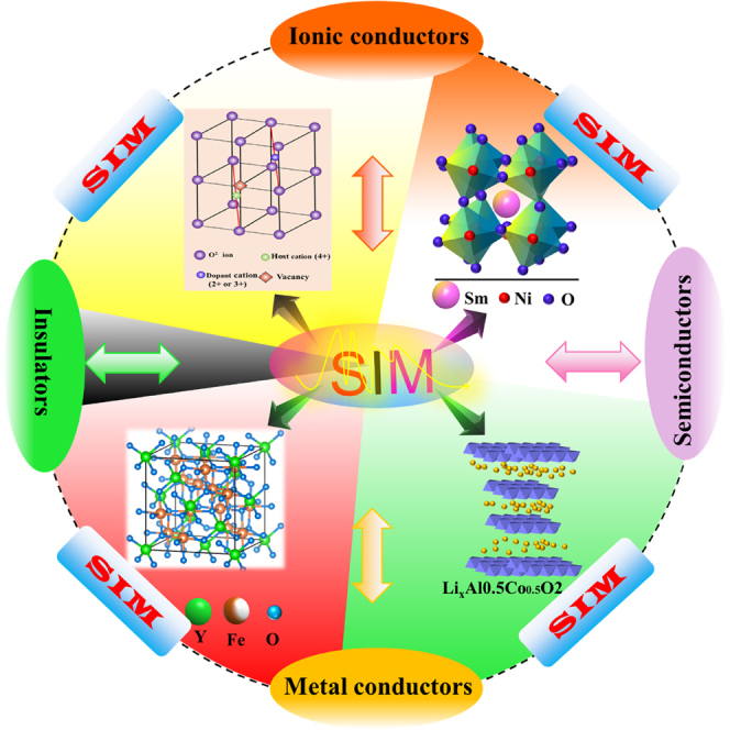
As shown in Figure 13, semiconductor-ionic material (SIM) systems have been widely investigated for various structural materials such as fluorite, perovskite, spinel, and layered structure systems.9,67,70,85,86,87,88,89,90,91,92,93,94,95,96,97,98,99,100,101,102,103,104,105,106,107,108 These heterostructure composite systems based on ionic-MOS or semiconductor-semiconductor materials make use of interfaces and interactions in the interfacial regions between two constituent phases, which result in interfacial conduction and charge transport highways, with significant impacts on the superionic conduction, redox reactions (hydrogen oxidation and oxygen reduction), catalyst, electrolysis, and fuel cell. The material architecture of the two-phase composite demonstrates a new scientific principle of material design and development, where the surface and interfacial mechanisms cause the conductivity and charge transfer enhancement.
Figure 13.

Semiconductor-ionic material (SIM) systems
Semiconductor-ionic material (SIM) systems with various structural materials such as fluorite, perovskite, spinel, and layered structure systems.
For example, Zhu et al. designed a semiconductor (LSCF), La0.6Sr0.4Co0.2Fe0.8O3-δ ionic (SCDC) Sm/Ca-codoped Ceria electrolyte owing specific properties toward a new generation of fuel cells. The utilized SIM electrolyte has revealed high ionic and electronic conductivity of >0.1 S/cm, higher OCV (>1.0 V), and fuel cell performance of 1000 mW/cm2 at 550°C. The HR-TEM image of the semiconductor ionic (LSCF-SCDC) heterostructure is shown in Figure 14B, whereas the energy band alignment mechanism is depicted in Figure 14C.109 In the same context, Xia and Mushtaq have designed new semiconductor ionic electrolyte materials, including STO-SDC (SrTiO3-Sm0.2Ce0.8O2), SFT-SDC (SrFe0.75Ti0.25O3-δ-Sm0.25Ce0.75O2) and delivered impressive fuel cell performance of 892 and 920 mW/cm2 with higher ionic conductivity of 0.14 and >0.1 S/cm at a low operating temperature of 550 and 520°C respectively.110,111 The Energy band diagram of SFT-SDC and schematic diagram including ORR and HOR mechanism, fuel cell performance, and SEM cross-sectional view of the pellet have been depicted in Figures 14A, 14D, and 14E. Furthermore, new semiconductor ionic heterostructure CeO2/BZY was used as an electrolyte, revealing maximum proton conduction of 0.23 S/cm and impressive fuel cell performance of 845 mW/cm2 at 520°C. Figures 14F and 14G shows the energy band diagram and proton transport mechanism on the surface and interface of CeO2& BZY.112 In addition, a new semiconductor heterostructure (LiCoO2-SnO2) based on bulk, bulk planar, and the thin-film-based planar junction was proposed as an electrolyte. It displayed higher fuel cell performance of 0.82, 0.61, and 0.28 W/cm2 at 600°C. Figure 14H shows the schematic diagram of a fuel cell of bulk heterostructure LiCoO2-SnO2 with fuel cell performance of different ratios between the LCO and SnO2 at a constant operational temperature of 600°C.113 The above-stated mechanism and reports differ from the conventional single-phase materials such as YSZ and SDC/GDC etc., where the high conductivity is realized by aliovalent doping to create oxygen vacancies inside the structure (a bulk mechanism), and device gaps/interfaces between the different components, e.g., anode, electrolyte, and cathode, which requires complex technology and strict condition to make the device functions, e.g., high temperature are needed to activate ionic mobility.9
Figure 14.

Energy band alingment, conduction mechnism and fuel cell performance of SFT-SDC, LSCF-SCDC, BZY/CeO2 and LCO/SnO2
(A) Energy band diagram of SFT-SDC and schematic diagram with HOR and ORR mechanism, (B and C) HR-TEM image of LSCF/SCDC and Energy band alignment mechanism, (D and E) I-V/I-P curve and SEM cross-sectional view of SFT-SDC, (F and G) Energy band diagram and proton transport mechanism on the surface of CeO2/BZY, (H) Schematic diagram based on bulk heterostructure LiCoO2-SnO2 with fuel cell performance of composite heterostructures.109,111,112,113 Copyright permission from the American Chemical Society and Elsevier.
Concluding remarks
The electrolyte materials have been the focus of developing SOFC technologies since Nernst first discovered the YSZ with a fluoride structure, as shown in Figure 15. Figure 15A shows that a low valency cation dopant, e.g., rare earth ions of Y3+ or Sm3+, to replace high valency Zr4+ or Ce4+ to create oxygen vacancy, enables the oxygen ion O2− to move through this vacancy. This structural design methodology has been central for the SOFC electrolyte and proton-conducting perovskites (BZ & BZY), as shown in Figures 15B and 15C.9,114 Replacing YSZ with new materials with high ionic conductivity at reduced temperatures, e.g., below 600°C, has not been successful so far.9,20
Figure 15.

Ionic conduction from structure design to semiconductor heterostructure
(A) O2− conducting fluoride with low valency cation dopant replace high valency Zr4+ or Ce4+ to create oxygen vacancy, then O2− move through this vacancy; perovskite proton conductor by the same way doping to create oxygen vacancies in (B) BaZrO3 structure to form (C) BZYO; and protons can move with two mechanisms as illustrated in (D) Grotthuss lattice oxygen transfer and (E) oxygen vacancy-vehicle mechanism. (F) in strong contrast, the superionic conduction is designed based on semiconductor heterostructure, e.g., pNaCoO3-nCeO2, where interfacial conduction mechanism with the help of built-in-electric field as a self-driving force on ionic transport9,18,114,115 permission with Elsevier, and Science.
The novel ceria-based nanocomposites and semiconductor-ionic heterostructure material systems reviewed in this paper represent new radical developments that could pave the way to next-generation low-temperature ceramic fuel cells operating in the range of 300–600°C at high power density. The underlying reason for such a performance improvement is surficial and interfacial ionic conduction.115 These materials rely on different design methodologies and functionalities than the traditional SOFC changing from the bulk inside the structure to particle surface and interfaces (Figures 15D–15F), especially the semiconductor heterostructure.
More interestingly, from these novel functional semiconductor heterostructure composite systems, the ionic conducting electrolyte concept can now be expanded on electrolyte-free or semiconductor membrane fuel cells based on the nano-redox principle,93,116,117 where a built-in-electric field can act as the second driving force to promote ionic transport.116,117 The fundamental understanding of this semiconductor-based membrane fuel cell technology is developed into a new discipline of semiconductor electrochemistry,98 which deserves more attention for next-generation fuel cell technology. We have reviewed novel solid material systems with high potential for next-generation fuel cells at 300–600°C. These employ ceramic nanocomposites based on semiconductor-ionic materials, either with core-shell or heterojunction structures. Power densities up to 1 Wcm−2 could be reached with these materials when used in a fuel cell device.
Acknowledgments
This work was supported by Southeast University (SEU) project 3203002003A1 and National Natural Science Foundation of China (NSFC) under the grant 51772080 and 11604088. Jiangsu Provincial Innovation and Entrepreneurship Talent program Project No. JSSCRC2021491. Industry-University-Research Cooperation Project of Jiangsu Province in China, Grant No. BY2021057.
Author contributions
M.A.K.Y.S.: Writing – original draft, redrawing figures, review and editing; B.Z. and P.D.L.: Revision, writing, editing, and supervision.
Declaration of interests
The author declares no competing interests.
Contributor Information
Peter D. Lund, Email: zhu-bin@seu.edu.cn.
Bin Zhu, Email: peter.lund@aalto.fi.
References
- 1.Grove W.R. XXIV. On voltaic series and the combination of gases by platinum. London, Edinburgh Dublin Phil. Mag. J. Sci. 1839;14:127–130. [Google Scholar]
- 2.Steele B.C., Heinzel A. Materials for sustainable energy: a collection of peer-reviewed research and review articles from Nature Publishing Group. World Scientific; 2011. Materials for fuel-cell technologies; pp. 224–231. [Google Scholar]
- 3.Wilson J.R., Kobsiriphat W., Mendoza R., Chen H.-Y., Hiller J.M., Miller D.J., Thornton K., Voorhees P.W., Adler S.B., Barnett S.A. Three-dimensional reconstruction of a solid-oxide fuel-cell anode. Nat. Mater. 2006;5:541–544. doi: 10.1038/nmat1668. [DOI] [PubMed] [Google Scholar]
- 4.Haile S.M., Boysen D.A., Chisholm C.R., Merle R.B. Solid acids as fuel cell electrolytes. Nature. 2001;410:910–913. doi: 10.1038/35073536. [DOI] [PubMed] [Google Scholar]
- 5.Jacobson M.Z., Colella W.G., Golden D.M. Cleaning the air and improving health with hydrogen fuel-cell vehicles. Science. 2005;308:1901–1905. doi: 10.1126/science.1109157. [DOI] [PubMed] [Google Scholar]
- 6.Jacobson A.J. Materials for solid oxide fuel cells. Chem. Mater. 2010;22:660–674. [Google Scholar]
- 7.Kerman K., Lai B.K., Ramanathan S. Nanoscale compositionally graded thin-film electrolyte membranes for low-temperature solid oxide fuel cells. Adv. Energy Mater. 2012;2:656–661. [Google Scholar]
- 8.Chen Y.-Y., Wei W.-C.J. Processing and characterization of ultra-thin yttria-stabilized zirconia (YSZ) electrolytic films for SOFC. Solid State Ionics. 2006;177:351–357. [Google Scholar]
- 9.Goodenough J.B. Oxide-ion conductors by design. Nature. 2000;404:821–823. doi: 10.1038/35009177. [DOI] [PubMed] [Google Scholar]
- 10.Singhal S. Vol. 10. 2013. (The SOFC-XIII Satellite Seminar). SOFC Market and Commercialization: Overview, Okinawa. [Google Scholar]
- 11.Saebea D., Authayanun S., Patcharavorachot Y., Chatrattanawet N., Arpornwichanop A. Electrochemical performance assessment of low-temperature solid oxide fuel cell with YSZ-based and SDC-based electrolytes. Int. J. Hydrogen Energy. 2018;43:921–931. [Google Scholar]
- 12.Naiqing Z., Kening S., Derui Z., Dechang J. Study on properties of LSGM electrolyte made by tape casting method and applications in SOFC. J. Rare Earths. 2006;24:90–92. [Google Scholar]
- 13.Bi L., Da'as E.H., Shafi S.P. Proton-conducting solid oxide fuel cell (SOFC) with Y-doped BaZrO3 electrolyte. Electrochem. Commun. 2017;80:20–23. [Google Scholar]
- 14.Yang L., Zuo C., Liu M. High-performance anode-supported Solid Oxide Fuel Cells based on Ba (Zr0. 1Ce0. 7Y0. 2) O3− δ (BZCY) fabricated by a modified co-pressing process. J. Power Sources. 2010;195:1845–1848. [Google Scholar]
- 15.Singhal S.C., Kendall K. Elsevier; 2003. High-temperature Solid Oxide Fuel Cells: Fundamentals, Design and Applications. [Google Scholar]
- 16.Iwahara H., Uchida H., Ono K., Ogaki K. Proton conduction in sintered oxides based on BaCeO3. J. Electrochem. Soc. 1988;135:529–533. [Google Scholar]
- 17.Iwahara H., Esaka T., Uchida H., Maeda N. Proton conduction in sintered oxides and its application to steam electrolysis for hydrogen production. Solid State Ionics. 1981;3–4:359–363. [Google Scholar]
- 18.Hossain M.K., Hashizume K., Hatano Y. Evaluation of the hydrogen solubility and diffusivity in proton-conducting oxides by converting the PSL values of a tritium imaging plate. Nucl. Mater. Energy. 2020;25:100875. [Google Scholar]
- 19.Park H.C., Virkar A.V. Bimetallic (Ni–Fe) anode-supported solid oxide fuel cells with gadolinia-doped ceria electrolyte. J. Power Sources. 2009;186:133–137. [Google Scholar]
- 20.Steele B. Appraisal of Ce Gd O electrolytes for IT-SOFC operation at 12y y 22y/2 5008C. Solid State Ionics. 2000;129:95–110. [Google Scholar]
- 21.Wachsman E.D., Lee K.T. Lowering the temperature of solid oxide fuel cells. Science. 2011;334:935–939. doi: 10.1126/science.1204090. [DOI] [PubMed] [Google Scholar]
- 22.Jamale A.P., Bhosale C.H., Jadhav L.D. Fabrication and characterization of La0.6Sr0. 4Co0.2Fe0. 8O3-δ (LSCF)-Ce0.9Gd0. 1O1. 95 (GDC) composite thick film for anode supported solid oxide fuel cells. J. Mater. Sci. Mater. Electron. 2016;27:795–799. [Google Scholar]
- 23.Li Y.T., Xie M.K., Wu J., Wang S. Chemical stability study of nanoscale thin film yttria-doped barium cerate electrolyte for micro solid oxide fuel cells. Biomed. Rep. 2014;2:804–808. [Google Scholar]
- 24.Zhu B. Advantages of intermediate temperature solid oxide fuel cells for tractionary applications. J. Power Sources. 2001;93:82–86. [Google Scholar]
- 25.Zhu B., Liu X., Zhou P., Yang X., Zhu Z., Zhu W. Innovative solid carbonate–ceria composite electrolyte fuel cells. Electrochem. Commun. 2001;3:566–571. [Google Scholar]
- 26.Zhu B., Yang X., Xu J., Zhu Z., Ji S., Sun M., Sun J. Innovative low temperature SOFCs and advanced materials. J. Power Sources. 2003;118:47–53. [Google Scholar]
- 27.Ferreira A.S., Soares C.M., Figueiredo F.M., Marques F.M. Intrinsic and extrinsic compositional effects in ceria/carbonate composite electrolytes for fuel cells. Int. J. Hydrogen Energy. 2011;36:3704–3711. [Google Scholar]
- 28.Li X., Xiao G., Huang K. Effective ionic conductivity of a novel intermediate-temperature mixed oxide-ion and carbonate-ion conductor. J. Electrochem. Soc. 2011;158:B225. [Google Scholar]
- 29.Ma Y., Wang X., Li S., Toprak M.S., Zhu B., Muhammed M. Samarium-doped ceria nanowires: novel synthesis and application in low-temperature solid oxide fuel cells. Adv. Mater. 2010;22:1640–1644. doi: 10.1002/adma.200903402. [DOI] [PubMed] [Google Scholar]
- 30.Amar I.A., Lan R., Petit C.T., Arrighi V., Tao S. Electrochemical synthesis of ammonia based on a carbonate-oxide composite electrolyte. Solid State Ionics. 2011;182:133–138. [Google Scholar]
- 31.Raza R., Zhu B., Rafique A., Naqvi M.R., Lund P. Functional ceria-based nanocomposites for advanced low-temperature (300–600° C) solid oxide fuel cell: a comprehensive review. Mater. Today Energy. 2020;15:100373. [Google Scholar]
- 32.Gao Z., Huang J., Mao Z., Wang C., Liu Z. Preparation and characterization of nanocrystalline Ce0.8Sm0. 2O1. 9 for low temperature solid oxide fuel cells based on composite electrolyte. Int. J. Hydrogen Energy. 2010;35:731–737. [Google Scholar]
- 33.Huang J., Gao R., Mao Z., Feng J. Investigation of La2NiO4+ δ-based cathodes for SDC–carbonate composite electrolyte intermediate temperature fuel cells. Int. J. Hydrogen Energy. 2010;35:2657–2662. [Google Scholar]
- 34.Jia L., Tian Y., Liu Q., Xia C., Yu J., Wang Z., Zhao Y., Li Y. A direct carbon fuel cell with (molten carbonate)/(doped ceria) composite electrolyte. J. Power Sources. 2010;195:5581–5586. [Google Scholar]
- 35.Zhao Y., Xia C., Wang Y., Xu Z., Li Y. Quantifying multi-ionic conduction through doped ceria-carbonate composite electrolyte by a current-interruption technique and product analysis. Int. J. Hydrogen Energy. 2012;37:8556–8561. [Google Scholar]
- 36.Dong X., Tian L., Li J., Zhao Y., Tian Y., Li Y. Single layer fuel cell based on a composite of Ce0. 8Sm0. 2O2− δ–Na2CO3 and a mixed ionic and electronic conductor Sr2Fe1. 5Mo0. 5O6− δ. J. Power Sources. 2014;249:270–276. [Google Scholar]
- 37.Zhao Y., Xu Z., Xia C., Li Y. Oxide ion and proton conduction in doped ceria–carbonate composite materials. Int. J. Hydrogen Energy. 2013;38:1553–1559. [Google Scholar]
- 38.Fang J., Li M., Li Q., Zhang W., Shou Q., Liu F., Zhang X., Cheng J. Microwave-assisted synthesis of CoAl-layered double hydroxide/graphene oxide composite and its application in supercapacitors. Electrochim. Acta. 2012;85:248–255. [Google Scholar]
- 39.Zhao L., Huang X., Zhu R., Lu Z., Sun W., Zhang Y., Ge X., Liu Z., Su W. Optimization on technical parameters for fabrication of SDC film by screen-printing used as electrolyte in IT-SOFC. J. Phys. Chem. Solid. 2008;69:2019–2024. [Google Scholar]
- 40.Ma Y., Wang X., Raza R., Muhammed M., Zhu B. Thermal stability study of SDC/Na2CO3 nanocomposite electrolyte for low-temperature SOFCs. Int. J. Hydrogen Energy. 2010;35:2580–2585. [Google Scholar]
- 41.Li X., Xu N., Zhang L., Huang K. Combining proton conductor BaZr0. 8Y0. 2O3-δ with carbonate: promoted densification and enhanced proton conductivity. Electrochem. Commun. 2011;13:694–697. [Google Scholar]
- 42.Di J., Chen M., Wang C., Zheng J., Fan L., Zhu B. Samarium doped ceria–(Li/Na) 2CO3 composite electrolyte and its electrochemical properties in low temperature solid oxide fuel cell. J. Power Sources. 2010;195:4695–4699. [Google Scholar]
- 43.Qin H., Zhu Z., Liu Q., Jing Y., Raza R., Imran S., Singh M., Abbas G., Zhu B. Direct biofuel low-temperature solid oxide fuel cells. Energy Environ. Sci. 2011;4:1273–1276. [Google Scholar]
- 44.Liu Q., Zhu B. Theoretical description of superionic conductivities in samaria doped ceria based nanocomposites. Appl. Phys. Lett. 2010;97:183115. [Google Scholar]
- 45.Wang X., Ma Y., Li S., Kashyout A.-H., Zhu B., Muhammed M. Ceria-based nanocomposite with simultaneous proton and oxygen ion conductivity for low-temperature solid oxide fuel cells. J. Power Sources. 2011;196:2754–2758. [Google Scholar]
- 46.Zhang L., Lan R., Kraft A., Tao S. A stable intermediate temperature fuel cell based on doped-ceria–carbonate composite electrolyte and perovskite cathode. Electrochem. Commun. 2011;13:582–585. [Google Scholar]
- 47.Mizuhata M., Ohashi T., Béléké A.B. Electrical conductivity of the coexisting system containing molten carbonates and rare-earth oxide. ECS Trans. 2010;33:439–447. [Google Scholar]
- 48.Fan L., Wang C., Chen M., Zhu B. Recent development of ceria-based (nano) composite materials for low temperature ceramic fuel cells and electrolyte-free fuel cells. J. Power Sources. 2013;234:154–174. [Google Scholar]
- 49.Raza R., Ahmad M.A., Iqbal J., Akram N., Gao Z., Javed S., Zhu B. Ce0. 8 (SmZr) 0.2 O2-carbonate nanocomposite electrolyte for solid oxide fuel cell. Int. J. Energy Res. 2014;38:524–529. [Google Scholar]
- 50.Khan M.A., Raza R., Lima R.B., Chaudhry M.A., Ahmed E., Khalid N., Abbas G., Zhu B., Nasir N. Effect of titania concentration on the grain boundary conductivity of calcium-doped ceria electrolyte. Ceram. Int. 2014;40:9775–9781. [Google Scholar]
- 51.Zhu B., Lund P., Raza R., Patakangas J., Huang Q.-A., Fan L., Singh M. A new energy conversion technology based on nano-redox and nano-device processes. Nano Energy. 2013;2:1179–1185. [Google Scholar]
- 52.Zhu B., Lund P.D., Raza R., Ma Y., Fan L., Afzal M., Patakangas J., He Y., Zhao Y., Tan W., et al. Schottky junction effect on high performance fuel cells based on nanocomposite materials. Adv. Energy Mater. 2015;5:1401895. [Google Scholar]
- 53.Fan L., Zhu B., Chen M., Wang C., Raza R., Qin H., Wang X., Wang X., Ma Y. High performance transition metal oxide composite cathode for low temperature solid oxide fuel cells. J. Power Sources. 2012;203:65–71. [Google Scholar]
- 54.Abbas G., Chaudhry M.A., Raza R., Singh M., Liu Q., Qin H., Zhu B. Study of CuNiZnGdCe-nanocomposite anode for low temperature SOFC. Nanosci. Nanotechnol. Lett. 2012;4:389–393. [Google Scholar]
- 55.Hu J., Tosto S., Guo Z., Wang Y. Dual-phase electrolytes for advanced fuel cells. J. Power Sources. 2006;154:106–114. [Google Scholar]
- 56.Zhu B. Next generation fuel cell R&D. Int. J. Energy Res. 2006;30:895–903. [Google Scholar]
- 57.Huang J., Xie F., Wang C., Mao Z. Development of solid oxide fuel cell materials for intermediate-to-low temperature operation. Int. J. Hydrogen Energy. 2012;37:877–883. [Google Scholar]
- 58.Xia C., Li Y., Tian Y., Liu Q., Zhao Y., Jia L., Li Y. A high performance composite ionic conducting electrolyte for intermediate temperature fuel cell and evidence for ternary ionic conduction. J. Power Sources. 2009;188:156–162. [Google Scholar]
- 59.Li Y., Rui Z., Xia C., Anderson M., Lin Y. Performance of ionic-conducting ceramic/carbonate composite material as solid oxide fuel cell electrolyte and CO2 permeation membrane. Catal. Today. 2009;148:303–309. [Google Scholar]
- 60.Rui Z., Anderson M., Lin Y., Li Y. Modeling and analysis of carbon dioxide permeation through ceramic-carbonate dual-phase membranes. J. Membr. Sci. 2009;345:110–118. [Google Scholar]
- 61.Bodén A., Di J., Lagergren C., Lindbergh G., Wang C.Y. Conductivity of SDC and (Li/Na) 2CO3 composite electrolytes in reducing and oxidising atmospheres. J. Power Sources. 2007;172:520–529. [Google Scholar]
- 62.Wang X., Ma Y., Zhu B. State of the art ceria-carbonate composites (3C) electrolyte for advanced low temperature ceramic fuel cells (LTCFCs) Int. J. Hydrogen Energy. 2012;37:19417–19425. [Google Scholar]
- 63.Fan L., Zhu B., Su P.-C., He C. Nanomaterials and technologies for low temperature solid oxide fuel cells: recent advances, challenges and opportunities. Nano Energy. 2018;45:148–176. [Google Scholar]
- 64.Huang J., Mao Z., Liu Z., Wang C. Development of novel low-temperature SOFCs with co-ionic conducting SDC-carbonate composite electrolytes. Electrochem. Commun. 2007;9:2601–2605. [Google Scholar]
- 65.Wang X., Ma Y., Raza R., Muhammed M., Zhu B. Novel core–shell SDC/amorphous Na2CO3 nanocomposite electrolyte for low-temperature SOFCs. Electrochem. Commun. 2008;10:1617–1620. [Google Scholar]
- 66.Zhang G., Deng X., Guan F., Bai Z., Cao L., Mao H., Tang C., Li C., He C., Zhang Q. Strongly coupled Sm0. 2Ce0. 8O2-Na2CO3 nanocomposite for low temperature solid oxide fuel cells: one-step synthesis and super interfacial proton conduction. Clin. Biomech. 2018;57:56–66. [Google Scholar]
- 67.Zhou X., Xia C., Wang X., Dong W., Wang B. Improving grain boundary conductivity of Ce0.9Gd0. 1O2− δ electrolyte through compositing with carbonate or semiconductor. Energy Technol. 2020;8:2000424. [Google Scholar]
- 68.Yue Bai J., Wang L., Jing Wang H., Fei Huang P., Qing Zhao Y., Di Fan S. Electrochemical behavior and determination of epinephrine at a mercaptoacetic acid self-assembled gold electrode. Microchim. Acta. 2006;156:321–326. [Google Scholar]
- 69.Huang J., Yang L., Gao R., Mao Z., Wang C. A high-performance ceramic fuel cell with samarium doped ceria–carbonate composite electrolyte at low temperatures. Electrochem. Commun. 2006;8:785–789. [Google Scholar]
- 70.Wang B., Zhu B., Yun S., Zhang W., Xia C., Afzal M., Cai Y., Liu Y., Wang Y., Wang H. Fast ionic conduction in semiconductor CeO2-δ electrolyte fuel cells. NPG Asia Mater. 2019;11:51. [Google Scholar]
- 71.Xing Y., Wu Y., Li L., Shi Q., Shi J., Yun S., Akbar M., Wang B., Kim J.-S., Zhu B. Proton shuttles in CeO2/CeO2− δ core–shell structure. ACS Energy Lett. 2019;4:2601–2607. [Google Scholar]
- 72.Akbar M., Jin B., Tu Z., Gao J., Yousaf M., Mushtaq N., Wang X., Dong W., Wang B., Cai Y., Xia C. High-performing and stable non-doped ceria electrolyte with amorphous carbonate coating layer for low-temperature solid oxide fuel cells. Electrochim. Acta. 2021;393:139067. [Google Scholar]
- 73.Kim J.-T., Lee T.-H., Park K.-Y., Seo Y., Kim K.B., Song S.-J., Park B., Park J.-Y. Electrochemical properties of dual phase neodymium-doped ceria alkali carbonate composite electrolytes in intermediate temperature. J. Power Sources. 2015;275:563–572. [Google Scholar]
- 74.Jing Y., Lund P., Asghar M.I., Li F., Zhu B., Wang B., Zhou X., Chen C., Fan L. Non-doped CeO2-carbonate nanocomposite electrolyte for low temperature solid oxide fuel cells. Ceram. Int. 2020;46:29290–29296. [Google Scholar]
- 75.Chen Y., Lin Y., Zhang Y., Wang S., Su D., Yang Z., Han M., Chen F. Low temperature solid oxide fuel cells with hierarchically porous cathode nano-network. Nano Energy. 2014;8:25–33. [Google Scholar]
- 76.Zhang C. Solid oxide fuel cells: low temperature cathodes. Nat. Energy. 2016;1:16200–16202. [Google Scholar]
- 77.Li P., Zhao Y., Yu B., Li J., Li Y. Improve electrical conductivity of reduced La2Ni0. 9Fe0. 1O4+ δ as the anode of a solid oxide fuel cell by carbon deposition. Int. J. Hydrogen Energy. 2015;40:9783–9789. [Google Scholar]
- 78.Peng X., Tian Y., Liu Y., Wang W., Pu J., Li J., Chi B., Li J. A double perovskite decorated carbon-tolerant redox electrode for symmetrical SOFC. Int. J. Hydrogen Energy. 2020;45:14461–14469. [Google Scholar]
- 79.Zhu B. Functional ceria–salt-composite materials for advanced ITSOFC applications. J. Power Sources. 2003;114:1–9. [Google Scholar]
- 80.Huang J., Mao Z., Liu Z., Wang C. Performance of fuel cells with proton-conducting ceria-based composite electrolyte and nickel-based electrodes. J. Power Sources. 2008;175:238–243. [Google Scholar]
- 81.Benamira M., Ringuedé A., Albin V., Vannier R.-N., Hildebrandt L., Lagergren C., Cassir M. Gadolinia-doped ceria mixed with alkali carbonates for solid oxide fuel cell applications: I. A thermal, structural and morphological insight. J. Power Sources. 2011;196:5546–5554. [Google Scholar]
- 82.Raza R., Abbas G., Wang X., Ma Y., Zhu B. Electrochemical study of the composite electrolyte based on samaria-doped ceria and containing yttria as a second phase. Solid State Ionics. 2011;188:58–63. [Google Scholar]
- 83.Zhang L., Lan R., Petit C.T., Tao S. Durability study of an intermediate temperature fuel cell based on an oxide–carbonate composite electrolyte. Int. J. Hydrogen Energy. 2010;35:6934–6940. [Google Scholar]
- 84.Wu J., Zhu B., Mi Y., Shih S.-J., Wei J., Huang Y. A novel core–shell nanocomposite electrolyte for low temperature fuel cells. J. Power Sources. 2012;201:164–168. [Google Scholar]
- 85.Garcia-Barriocanal J., Rivera-Calzada A., Varela M., Sefrioui Z., Iborra E., Leon C., Pennycook S.J., Santamaria J. Colossal ionic conductivity at interfaces of epitaxial ZrO2: Y2O3/SrTiO3 heterostructures. Science. 2008;321:676–680. doi: 10.1126/science.1156393. [DOI] [PubMed] [Google Scholar]
- 86.Zhou Y., Guan X., Zhou H., Ramadoss K., Adam S., Liu H., Lee S., Shi J., Tsuchiya M., Fong D.D., Ramanathan S. Strongly correlated perovskite fuel cells. Nature. 2016;534:231–234. doi: 10.1038/nature17653. [DOI] [PubMed] [Google Scholar]
- 87.Chen G., Zhu B., Deng H., Luo Y., Sun W., Liu H., Zhang W., Wang X., Qian Y., Hu X., et al. Advanced fuel cell based on perovskite La–SrTiO3 semiconductor as the electrolyte with superoxide-ion conduction. ACS Appl. Mater. Interfaces. 2018;10:33179–33186. doi: 10.1021/acsami.8b10087. [DOI] [PubMed] [Google Scholar]
- 88.Shah M.Y., Mushtaq N., Rauf S., Akbar N., Xing Y., Wu Y., Wang B., Zhu B. Advanced fuel cell based on semiconductor perovskite La–BaZrYO3-δ as an electrolyte material operating at low temperature 550° C. Int. J. Hydrogen Energy. 2020;45:27501–27509. [Google Scholar]
- 89.Singh K., Nowotny J., Thangadurai V. Amphoteric oxide semiconductors for energy conversion devices: a tutorial review. Chem. Soc. Rev. 2013;42:1961–1972. doi: 10.1039/c2cs35393h. [DOI] [PubMed] [Google Scholar]
- 90.Shah M.A.K.Y., Zhu B., Rauf S., Mushtaq N., Yousaf M., Ali N., Tayyab Z., Akbar N., Yang C.P., Wang B. Electrochemical properties of a co-doped SrSnO3− δ-based semiconductor as an electrolyte for solid oxide fuel cells. ACS Appl. Energy Mater. 2020;3:6323–6333. [Google Scholar]
- 91.Hu E., Jiang Z., Fan L., Singh M., Wang F., Raza R., Sajid M., Wang J., Kim J.-S., Zhu B. Junction and energy band on novel semiconductor-based fuel cells. iScience. 2021;24:102191. doi: 10.1016/j.isci.2021.102191. [DOI] [PMC free article] [PubMed] [Google Scholar]
- 92.Rauf S., Zhu B., Shah M., Tayyab Z., Attique S., Ali N., Mushtaq N., Asghar M., Lund P., Yang C. Low-temperature solid oxide fuel cells based on Tm-doped SrCeO2-δ semiconductor electrolytes. Mater. Today Energy. 2021;20:100661. [Google Scholar]
- 93.Lund T.L. Nano-scale view into solid oxide fuel cell and semiconductor 3 membrane fuel cell: material and technology 4. Perspective. 2021;1:2. [Google Scholar]
- 94.Zhu B., Mi Y., Xia C., Wang B., Kim J.-S., Lund P., Li T. A nanoscale perspective on solid oxide and semiconductor membrane fuel cells: materials and technology. Energy Mater. 2022;1:100002. [Google Scholar]
- 95.Shah M.A.K.Y., Rauf S., Mushtaq N., Zhu B., Tayyab Z., Yousaf M., Hanif M.B., Lund P.D., Lu Y., Asghar M.I. Novel perovskite semiconductor based on Co/Fe-codoped LBZY (La0. 5Ba0. 5 Co0. 2Fe0. 2Zr0. 3Y0. 3O3− δ) as an electrolyte in ceramic fuel cells. ACS Appl. Energy Mater. 2021;4:5798–5808. [Google Scholar]
- 96.Shah M.Y., Lu Y., Mushtaq N., Yousaf M., Rauf S., Asghar M.I., Lund P.D., Zhu B. Perovskite Al-SrTiO 3 semiconductor electrolyte with superionic conduction in ceramic fuel cells. Sustain. Energy Fuels. 2022;6:3794–3805. [Google Scholar]
- 97.Lu Y., Mi Y., Li J., Qi F., Yan S., Dong W. Recent progress in semiconductor-ionic conductor nanomaterial as a membrane for low-temperature solid oxide fuel cells. Nanomaterials. 2021;11:2290. doi: 10.3390/nano11092290. [DOI] [PMC free article] [PubMed] [Google Scholar]
- 98.Zhu B., Fan L., Mushtaq N., Raza R., Sajid M., Wu Y., Lin W., Kim J.-S., Lund P.D., Yun S. Semiconductor electrochemistry for clean energy conversion and storage. Electrochem. Energy Rev. 2021;4:757–792. [Google Scholar]
- 99.Xia C., Qiao Z., Shen L., Liu X., Cai Y., Xu Y., Qiao J., Wang H. Semiconductor electrolyte for low-operating-temperature solid oxide fuel cell: Li-doped ZnO. Int. J. Hydrogen Energy. 2018;43:12825–12834. [Google Scholar]
- 100.Shah M.Y., Rauf S., Mushtaq N., Tayyab Z., Ali N., Yousaf M., Xing Y., Akbar M., Lund P.D., Yang C.P., et al. Semiconductor Fe-doped SrTiO3-δ perovskite electrolyte for low-temperature solid oxide fuel cell (LT-SOFC) operating below 520° C. Int. J. Hydrogen Energy. 2020;45:14470–14479. [Google Scholar]
- 101.Shah M.A.K.Y., Rauf S., Zhu B., Mushtaq N., Yousaf M., Lund P.D., Xia C., Asghar M.I. Semiconductor Nb-doped SrTiO3− δ perovskite electrolyte for a ceramic fuel cell. ACS Appl. Energy Mater. 2021;4:365–375. [Google Scholar]
- 102.Dong W., Tong Y., Zhu B., Xiao H., Wei L., Huang C., Wang B., Wang X., Kim J.-S., Wang H. Semiconductor TiO 2 thin film as an electrolyte for fuel cells. J. Mater. Chem. A Mater. 2019;7:16728–16734. [Google Scholar]
- 103.Zhu B., Yun S., Lund P.D. Wiley Online Library; 2018. Semiconductor-ionic Materials Could Play an Important Role in Advanced Fuel-to-electricity Conversion. [Google Scholar]
- 104.Xia C., Mi Y., Wang B., Lin B., Chen G., Zhu B. Shaping triple-conducting semiconductor BaCo0.4Fe0. 4Zr0. 1Y0.1O3-δ into an electrolyte for low-temperature solid oxide fuel cells. Nat. Commun. 2019;10:1707–1709. doi: 10.1038/s41467-019-09532-z. [DOI] [PMC free article] [PubMed] [Google Scholar]
- 105.Fan L., Wang C., Osamudiamen O., Raza R., Singh M., Zhu B. Mixed ion and electron conductive composites for single component fuel cells: I. Effects of composition and pellet thickness. J. Power Sources. 2012;217:164–169. [Google Scholar]
- 106.Fan L., Ma Y., Wang X., Singh M., Zhu B. Understanding the electrochemical mechanism of the core–shell ceria–LiZnO nanocomposite in a low temperature solid oxide fuel cell. J. Mater. Chem. A Mater. 2014;2:5399–5407. [Google Scholar]
- 107.Lund P.D., Zhu B., Li Y., Yun S., Nasibulin A.G., Raza R., Leskelä M., Ni M., Wu Y., Chen G., et al. Standardized procedures important for improving single-component ceramic fuel cell technology. ACS Energy Lett. 2017;2:2752–2755. [Google Scholar]
- 108.Shao K., Li F., Zhang G., Zhang Q., Maliutina K., Fan L. Approaching durable single-layer fuel cells: promotion of electroactivity and charge separation via nanoalloy redox exsolution. ACS Appl. Mater. Interfaces. 2019;11:27924–27933. doi: 10.1021/acsami.9b08448. [DOI] [PubMed] [Google Scholar]
- 109.Zhu B., Wang B., Wang Y., Raza R., Tan W., Kim J.-S., Van Aken P.A., Lund P. Charge separation and transport in La0.6Sr0. 4Co0.2Fe0. 8O3-δ and ion-doping ceria heterostructure material for new generation fuel cell. Nano Energy. 2017;37:195–202. [Google Scholar]
- 110.Cai Y., Chen Y., Akbar M., Jin B., Tu Z., Mushtaq N., Wang B., Qu X., Xia C., Huang Y. A bulk-heterostructure nanocomposite electrolyte of Ce0.8Sm0. 2O2-δ–SrTiO3 for low-temperature solid oxide fuel cells. Nano-Micro Lett. 2021;13:46. doi: 10.1007/s40820-020-00574-3. [DOI] [PMC free article] [PubMed] [Google Scholar]
- 111.Mushtaq N., Xia C., Dong W., Wang B., Raza R., Ali A., Afzal M., Zhu B. Tuning the energy band structure at interfaces of the SrFe0.75Ti0. 25O3− δ–Sm0. 25Ce0.75O2− δ heterostructure for fast ionic transport. ACS Appl. Mater. Interfaces. 2019;11:38737–38745. doi: 10.1021/acsami.9b13044. [DOI] [PubMed] [Google Scholar]
- 112.Xing Y., Zhu B., Hong L., Xia C., Wang B., Wu Y., Cai H., Rauf S., Huang J., Asghar M.I., et al. Designing high interfacial conduction beyond bulk via engineering the semiconductor–ionic heterostructure CeO2− δ/BaZr0.8Y0. 2O3 for superior proton conductive fuel cell and water electrolysis applications. ACS Appl. Energy Mater. 2022;5:15373–15384. doi: 10.1021/acsaem.2c02995. [DOI] [PMC free article] [PubMed] [Google Scholar]
- 113.Ganesh K.S., Fan L., Wang B., Jeevan Kumar P., Zhu B. Built-in electric field for efficient charge separation and ionic transport in LiCoO2/SnO2 semiconductor junction fuel cells. ACS Appl. Energy Mater. 2022;5:12513–12522. [Google Scholar]
- 114.Hossain M.K., Biswas M.C., Chanda R.K., Rubel M.H.K., Khan M.I., Hashizume K. A review on experimental and theoretical studies of perovskite barium zirconate proton conductors. Emergent Mater. 2021;4:999–1027. [Google Scholar]
- 115.Ni M.F., Wang X.M., Wang H.Y., Chang Y., Huang X.F., Zhang B.W. Fuel cells that operate at 300 to 500 C. Science. 2020;277:138–145. [Google Scholar]
- 116.Lu Y., Zhu B., Shi J., Yun S. Advanced low-temperature solid oxide fuel cells based on a built-in electric field. Energy Mater. 2022;1:100007. [Google Scholar]
- 117.Shah M.Y., Lu Y., Mushtaq N., Singh M., Rauf S., Yousaf M., Zhu B. 2022. ZnO/MgZnO Heterostructure Membrane with Type II Band Alignment for Ceramic Fuel Cells. [Google Scholar]