Abstract
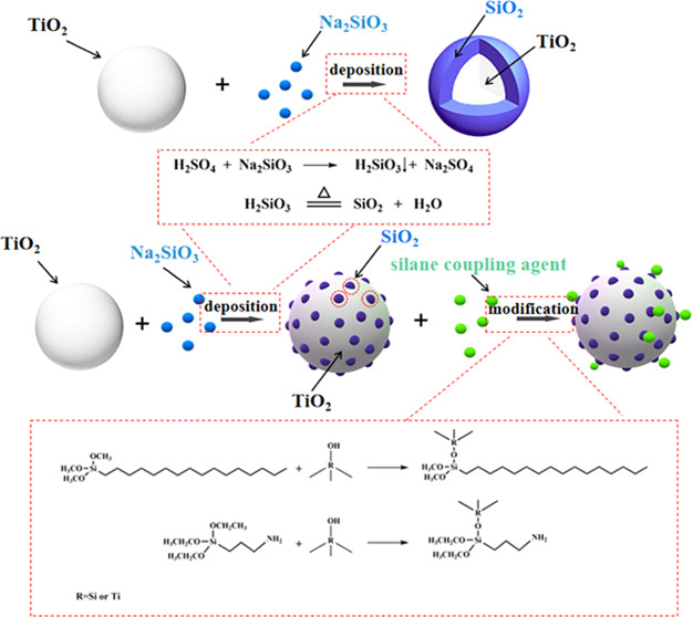
The grafted modification TiO2@SiO2 composite was fabricated by a liquid-phase deposition method with Na2SiO3 and a grafting reaction with a silane coupling agent. First, the TiO2@SiO2 composite was prepared, and the effect of deposition rate and silica content on the morphology, particle size, dispersibility, and pigmentary property of TiO2@SiO2 composites was investigated by scanning electron microscopy (SEM), transmission electron microscopy (TEM), Fourier transform infrared (FTIR) spectroscopy, energy-dispersive X-ray spectroscopy (EDX), X-ray photoelectron spectroscopy (XPS), and ζ-potential. The islandlike TiO2@SiO2 composite had a good particle size and printing performance compared with the dense TiO2@SiO2 composite. The presence of Si was confirmed by EDX elemental analysis and XPS, and a peak at 980 cm–1 belonging to Si–O was observed in the FTIR spectrum, confirming the presence of SiO2 anchored at TiO2 surfaces via Si–O–Ti bonds. Then, the islandlike TiO2@SiO2 composite was modified by grafting with a silane coupling agent. The effect of the silane coupling agent on the hydrophobicity and dispersibility was investigated. The peaks at 2919 and 2846 cm–1 belong to CH2 in the FTIR spectrum, and Si–C in the XPS confirmed the grafting of silane coupling agent to the TiO2@SiO2 composite. The grafted modification of the islandlike TiO2@SiO2 composite using 3-triethoxysilylpropylamine endowed it with weather durability, dispersibility, and good printing performance.
1. Introduction
Titanium dioxide (TiO2) is the best white pigment due to its excellent optical properties, which is widely used in coatings, plastics, paper, ink, and other industries. However, TiO2 particles generate electrons and holes under ultraviolet light and then react with water and oxygen to generate free radicals, which leads to the degradation of organic matter around the TiO2 particles.1−4 The photocatalytic performance of TiO2 causes defects such as breakage and yellowing of the adhesive. In order to increase the weather resistance of TiO2 particles, the surface of TiO2 particles was coated with an inert oxide barrier film, such as silica and alumina.5,6 A liquid-phase deposition method was usually used for inorganic thin-film coating. By adding the inorganic salt and acid/alkali solution to the TiO2 suspension, a layer of oxide or hydroxide film was coated on the surface of the TiO2 particles, which increased the weather resistance of the TiO2 particles.7,8 The SiO2 coating layers increased the amount of OH groups on the surfaces of TiO2 particles, which improved the dispersibility of TiO2 particles in aqueous media and provided more active sites for the subsequent organic modification.9,10 Zhang et al. used zirconium dioxide to coat TiO2, and the prepared TiO2@ZrO2 had good weather resistance, whiteness, and brightness.11
Although the coating of inorganic metal oxide on the surface of TiO2 inhibited the photocatalytic performance of TiO2, the refractive index of inorganic metal oxide was lower than that of TiO2, resulting in the decrease of covering performance of inorganic metal oxide-coated titanium dioxide particles. Liang et al. applied inorganic metal oxides to coat TiO2 to improve the weather resistance of TiO2. The results showed that the coating of dense films of inorganic metal oxides greatly reduced the covering properties of TiO2.12 Wang et al. found that the use of a yolk–shell structure and a porous film could solve the problems of poor weather resistance and reduced the covering performance of inorganic oxide-coated titanium dioxide.13
In the titanium dioxide printing paste formula, the amount of TiO2 was very high and it was insoluble in water so the aggregation of TiO2 in the printing paste formula could easily occur. When the titanium dioxide aggregated, its increased particle size reduced its optical properties. In order to improve the dispersibility of TiO2, a lot of studies have been carried out, among which the chemical modification of TiO2 was a more effective method.14 The silane coupling agents were applied to the chemical modification of inorganic particulates, improving the stability and dispersibility.15 Wang et al. used γ-methacrylic acyloxy propyl trimethoxysilane to chemically modify TiO2, which changed the hydrophobicity of TiO2 and improved the dispersion stability.16 The thermoplastic resin was used to improve the stability and dispersibility of pigment by chemical modification.17
In this study, the TiO2 pigment was coated with an islandlike or dense structure of silica by controlling the precipitation rate of SiO2. The effect of precipitation rate and silica content on the morphology, ζ-potential, particle size, dispersibility, and pigment property of TiO2@SiO2 composites was investigated. To further improve the dispersibility and printing performance, the TiO2@SiO2 composite was subjected to chemical modification with silane coupling agents by ultrasound treatment. The chemical structure of the grafted modification TiO2@SiO2 composites was analyzed in detail. For coating treatment and hydrophilic modification, the printing performance of hydrophilic modification TiO2@SiO2 composites was improved.
2. Materials and Methods
2.1. Materials
The 40 s × 40 s plain-woven pure cotton fabric (weighing 116 g/m2) was provided by Hualun Co., Ltd. The TiO2, sodium metasilicate nonahydrate, sodium hexametaphosphate, 3-triethoxysilylpropylamine (APTES), sulfuric acid, and ammonia were obtained from Shanghai Aladdin Biochemical Technology Co., Ltd. The acrylic binder, acrylic thickener, and dispersant were provided by Zhejiang Transchem Chemical Group. The hexadecyltrimethoxysilane (HDTMS) and rhodamine-B were obtained from Macklin Inc.
2.2. Process of Preparing TiO2@SiO2 and Grafted Modification TiO2@SiO2
2.2.1. Preparing the TiO2@SiO2 Composite
The surface of TiO2 nanoparticles was coated with SiO2 nanoparticles. First, TiO2 nanoparticles (20 g) and sodium hexametaphosphate (0.1 g) were dispersed in 80 mL of deionized water with the aid of ultrasonication for 30 min in the solution of pH = 9–10, and the solution was stirred vigorously for 30 min. Next, a certain amount of sodium metasilicate nonahydrate (0.3 mol/L) was injected into the mixture using a syringe pump at a rate of 1.0 or 4.0 mL/min at 85 °C. At the same time, the pH of the solution was maintained by adding H2SO4 (1.6 wt %). After injecting, the resulting TiO2@SiO2 particles were centrifuged, washed 3–5 times with ethanol, dried under vacuum, and ground.
2.2.2. Surface Grafting Modification of TiO2@SiO2 Particles
The surface of the TiO2@SiO2 composite was subjected to grafting modification with APTES or HDTMS. The TiO2@SiO2 composite (10 g) was dispersed in a mixture of sodium hexametaphosphate (0.4 g), ammonia (1.5 g), and deionized water (150 mL). After stirring for 30 min, APTES or HDTMS (10 wt %) was injected into the mixture. Then, the solution was sonicated and stirred vigorously for 4 h. After sonicating and stirring, the resulting grafted modification TiO2@SiO2 composites were centrifuged, washed 3–5 times with ethanol, dried under vacuum, and ground.
2.3. Process of Printing Cotton Fabric
First, a proper amount of binder, dispersant, and TiO2 particles was added to water to form a dispersion system, which was stirred evenly under a mechanical stirrer (1000 rpm). Then, the thickener was slowly added to it to make the printing paste with a certain viscosity. The printing paste formula was printed on the cotton fabric; then, the sample was dried at 80 °C for 5 min and baked at 150 °C for 5 min.
2.4. Analysis and Measurements
2.4.1. ζ-Potential Measurement
The sample was diluted to a certain concentration and prepared as a suspension. The sample was put into the ζ-potential analyzer to measure the ζ-potential.
2.4.2. Particle Size Measurement
The sample was diluted to a certain concentration and prepared as a suspension, which was put into a nanoparticle sizer to measure the particle size.
2.4.3. SEM, EDX, and TEM Measurement
The sample was dispersed in deionized water; then, the sample was treated by ultrasound for 20 min. The sample was observed with a field-emission scanning electron microscope equipped with an energy-dispersive X-ray spectrometer (S-4800, Hitachi, Japan) and TEM (H-9500, Hitachi, Japan).
2.4.4. X-ray Photoelectron Spectroscopy
The chemical composition of the particle was examined by X-ray photoelectron spectrometry (XPS, Thermo ESCALAB 250).
2.4.5. ATR-FTIR Spectroscopy
The attenuated total reflectance-Fourier transform spectroscopy (ATR-FTIR) spectra of the sample were recorded on a Spectrum II (PerkinElmer) in the range of 4000–400 cm–1.
2.4.6. Contact Angle Measurement
The hydrophobic property of particle was measured via an optical contact angle meter system (DSA100, Germany).
2.4.7. Printing Performance and Weather Durability Measurement
The printed sample was measured by a Datacolor 650 to obtain the reflectance of blackboard and whiteboard printed by printing paste formula. The contrast ratio was the ratio of the reflectivity of the blackboard and the whiteboard. The whiteness of printed cotton fabrics was measured by WSB-2 intelligent whiteness tester. Weather durability measurement was referred from a previous research.13
3. Results and Discussion
3.1. Synthesis and Characterization of TiO2@SiO2
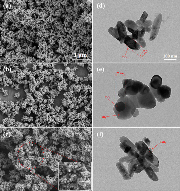
The TiO2@SiO2 composite was prepared via a liquid-phase deposition method with Na2SiO3. The deposition rate controlled by the drip rate of Na2SiO3 and H2SO4 was a significant factor that influenced the morphology of TiO2@SiO2. As seen in Figure 1a,d, the naked TiO2 was a rod structure with a length of about 240 nm and a width of about 70 nm. With the deposition of SiO2 on the surface of TiO2 at a faster drip rate of Na2SiO3 and H2SO4 (4.0 mL/min), the obvious dense spherical SiO2-coated rodlike TiO2 composite was formed (shown in Figure 1b,e). As shown in Figure 1e, the size of this composite was increased compared with naked TiO2. When the drip rate of Na2SiO3 and H2SO4 was slow (1.0 mL/min), the deposition rate of SiO2 on the surface of TiO2 was also decreased accordingly so that the morphology of TiO2@SiO2 was different from TiO2@SiO2 at a faster drip rate (4.0 mL/min). As seen from Figure 1c,f, the islandlike layer of SiO2 on the surface of TiO2 was prepared.
Figure 1.
SEM images: (a) naked TiO2, (b) dense TiO2@SiO2, and (c) islandlike TiO2@SiO2. TEM images: (d) naked TiO2, (e) dense TiO2@SiO2, and (f) islandlike TiO2@SiO2.
The morphology of TiO2@SiO2 prepared by different drip rates was different due to the deposition rate of SiO2 on the surface of TiO2. In the liquid-phase deposition method, the TiO2 particle acted as a crystal nucleus and the generation of SiO2 grew on its surface. At a faster drip rate of Na2SiO3 and H2SO4, SiO2 was generated quickly and a larger amount of SiO2 was deposited on the TiO2 particle to prepare dense TiO2@SiO2. However, at a slow drip rate, generated SiO2 was randomly deposited on the surface of TiO2 to obtain islandlike TiO2@SiO2.
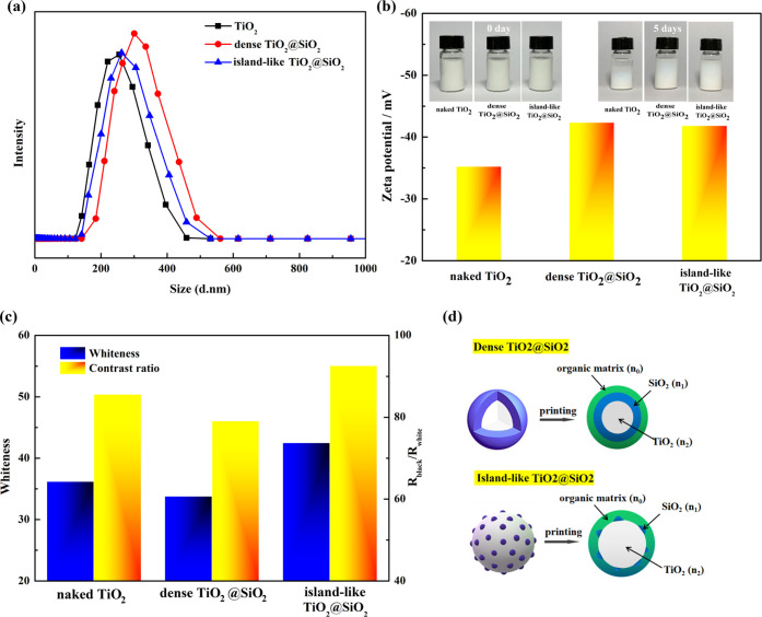
Figure 2a shows the particle size, dispersion stability, and ζ-potential of the naked TiO2, dense TiO2@SiO2, and islandlike TiO2@SiO2. As seen in Figure 2a, the average particle size of naked TiO2, dense TiO2@SiO2, and islandlike TiO2@SiO2 was 253, 318, and 286 nm, respectively. The size of dense TiO2@SiO2 increased obviously compared with naked TiO2. The dispersion stability of TiO2@SiO2 after 5 days improved due to the decrease of ζ-potential, which contributed to the electrostatic stabilization of TiO2@SiO2 composites compared with naked TiO2 (shown in Figure 2b). As seen in Figure 2c, the whiteness of printed cotton fabric and contrast ratio using naked TiO2 were 36.2 and 85.6%, respectively. Compared with naked TiO2, the whiteness and contrast ratio using dense TiO2@SiO2 declined, and the whiteness and contrast ratio using islandlike TiO2@SiO2 were increased to 42.5 and 92.6%, respectively. The hiding power was related to the square of the difference between the refractive index of the pigment and the organic matrix. Theoretically, naked TiO2 particles had high hiding performance due to the high difference of refractive index between TiO2 particles and its surroundings. For the TiO2@SiO2 composite, the surrounding was the SiO2 film (n1) instead of an organic matrix (n0) (shown in Figure 2d). The difference of refractive indices between SiO2 particle (n1) and organic matrix (n0) was lower than the difference of refractive indices between TiO2 particle (n2) and organic matrix (n0) so that the hiding power of the dense TiO2@SiO2 composite declined. For the islandlike TiO2@SiO2 composite, the surrounding of TiO2 particle was partly replaced by SiO2 particle compared with the dense TiO2@SiO2 composite so that the difference of refractive indices was not declined obviously. In addition, the deposition of SiO2 particle on the surface of TiO2 particle, increasing the ζ-potential of the TiO2@SiO2 composite, contributed to the dispersibility of the TiO2@SiO2 composite in the printing formula so that the hiding performance of the islandlike TiO2@SiO2 composite was improved. Therefore, the islandlike TiO2@SiO2 composite is discussed in the following section.
Figure 2.
(a) Particle size of the naked TiO2, dense TiO2@SiO2 composite, and islandlike TiO2@SiO2 composite. (b) Dispersion stability and ζ-potential of different particles. (c) Printing performance of different particles, and (d) schematic diagram of the TiO2@SiO2 composite.
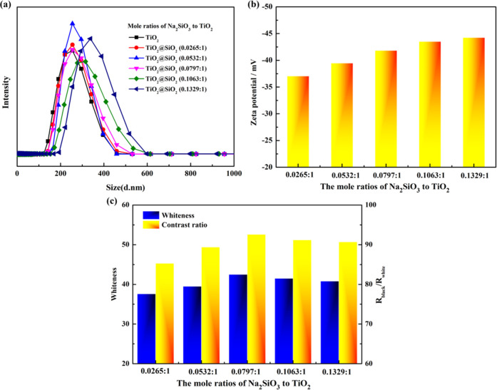
The effect of mole ratios of Na2SiO3 to TiO2 on the particle size, ζ-potential, and printing performance of the islandlike TiO2@SiO2 composite is shown in Figure 3. As seen in Figure 3a,b, with the increase of mole ratios of Na2SiO3 to TiO2 from 0.0265:1 to 0.1329:1, the average particle size increased from 262 to 350 nm, and the ζ-potential decreased from −38.2 to −43.8 mV. As shown in Figure 3c, with an increase of mole ratios of Na2SiO3 to TiO2 from 0.0265:1 to 0.0797:1, the whiteness and contrast ratio increased from 37.6 to 42.5 and from 85.3 to 92.6%, respectively. With further increase in mole ratios above 0.0797:1, the whiteness and contrast ratio declined. The reason for this phenomenon was that at higher mole ratios, the size of the islandlike TiO2@SiO2 composite became large and the massively deposited SiO2 on the surface of TiO2 resulted in the decrease of refractive indices. Therefore, the mole ratio of Na2SiO3 to TiO2 of 0.0797:1 was the optimum condition to obtain the islandlike TiO2@SiO2 composite with good printing performance.
Figure 3.
Effect of mole ratios of Na2SiO3 to TiO2 on the particle size (a), ζ-potential (b), and printing performance (c) of the islandlike TiO2@SiO2 composite.
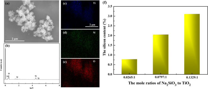
The chemical structure of the islandlike TiO2@SiO2 composite was analyzed by EDX, FTIR, and XPS in Figures 4 and 5. The EDX spectroscopy of the islandlike TiO2@SiO2 composite is shown in Figure 4b, indicating that the sample was composed of the elements Ti, O, and Si. The EDX elemental mapping figure of Ti, O, and Si shown in Figure 4c–e indicated the distribution of the SiO2 on the surface of TiO2 was homogeneous. As seen in Figure 4f, with an increase of mole ratios of Na2SiO3 to TiO2 from 0.0265:1 to 0.1329:1, the silicon content increased from 0.79 to 3.12%.
Figure 4.
(a) SEM images of the islandlike TiO2@SiO2 composite. (b) EDX spectroscopy of the islandlike TiO2@SiO2 composite. (c–e) Elemental mapping of Ti, Si, and O, and (f) silicon content of the islandlike TiO2@SiO2 composite.
Figure 5.
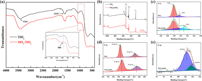
(a) FTIR spectrum of the naked TiO2 and the islandlike TiO2@SiO2 composite. (b) Representative XPS spectra of the naked TiO2 and islandlike TiO2@SiO2 composite. (c–e) High-resolution XPS spectra of O 1s, Ti 2p, and Si 2p.
As seen in Figure 5a, the absorption at 3326 cm–1 was attributed to O–H stretching vibration,18 and the absorption at 1630 cm–1 was attributed to the O–H bending vibration of adsorbed water molecules.19 The absorption in the 400–1200 cm–1 exhibited characteristic peaks of O–Ti–O.20 Compared with the naked TiO2 particle, the islandlike TiO2@SiO2 exhibited a new peak at 980 cm–1, which was assigned to the Si–O bond, confirming the coating of SiO2 on the surface of TiO2 particles.21Figure 5b shows representative XPS spectra of the naked TiO2 and the islandlike TiO2@SiO2 composite. The obvious peaks of C 1s, Ti 2p, and O 1s appeared in the naked TiO2 and the islandlike TiO2@SiO2 composite. Compared with the naked TiO2 particle, the new peak of Si 2p appeared in the islandlike TiO2@SiO2 composite. To investigate the chemical composition and valence states, high-resolution XPS spectroscopy was conducted (shown in Figure 5c–e). Figure 5c shows the deconvolution of O 1s spectra. For the naked TiO2, there were two peaks; the peak at 529.8 eV was assigned to the Ti–O bond and the peak at 531.3 eV was associated with the O–H bond.22 Compared with the naked TiO2, three peaks appeared in the islandlike TiO2@SiO2 composite. The new peak at 532.9 eV was assigned to the Si–O bond, showing the presence of SiO2 deposited on the surface of TiO2 particles.23 The two peaks at 458.6 and 464.3 eV assigned to Ti 2p3/2 and Ti 2p1/2 all appeared in naked TiO2 and the islandlike TiO2@SiO2 composite (shown in Figure 5d).24 Compared with the naked TiO2, the position of the peak in the islandlike TiO2@SiO2 composite was shifted, which was caused by the formation of the Si–O–Ti bond. Only the islandlike TiO2@SiO2 composite had two peaks at 102.2 and 103.5 eV for Si 2p, which were assigned to Si–O–Ti and Si–O–Si (seen in Figure 5e).25 The above XPS results were in good agreement with the EDX and FTIR spectra, indicating the coating of SiO2 on the surface of TiO2 particles in the islandlike TiO2@SiO2 composite via Si–O–Ti bonds.
3.2. Grafted Modification of Islandlike TiO2@SiO2 and Characterization
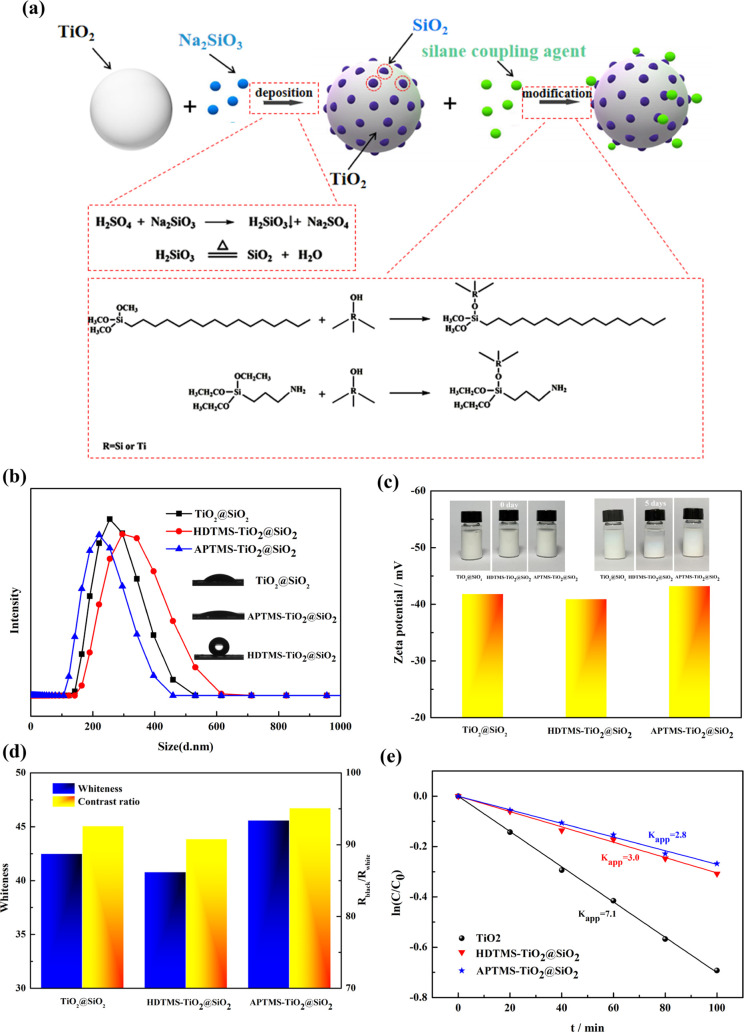
To investigate the effect of hydrophilic properties of particle on the dispersibility and printing performance, the islandlike TiO2@SiO2 composite was subjected to grafted modification with APTMS and HDTMS. The synthesis process to prepare grafted modification islandlike TiO2@SiO2 is shown in Figure 6a. Figure 6b shows the effect of APTMS and HDTMS on the size of the grafted modification TiO2@SiO2 composite. As seen from Figure 6b, for the HDTMS-TiO2@SiO2 composite, the particle size increased to 308 nm; however, the size of the APTMS-TiO2@SiO2 composite decreased compared with the islandlike TiO2@SiO2 composite. Figure 6b shows that the water contact angle of APTMS-TiO2@SiO2 was decreased to 15.2° and that of HDTMS-TiO2@SiO2 was increased to 126.2° compared with the islandlike TiO2@SiO2 composite (29.4°). The water contact angle was higher than 90°, indicating the particle had hydrophobic properties. The enhanced hydrophilic properties of the APTMS-TiO2@SiO2 composite resulted in the improvement of dispersibility so that the size of the APTMS-TiO2@SiO2 composite decreased. The dispersibility stability and ζ-potential of the APTMS-TiO2@SiO2 composite were also better than that of the islandlike TiO2@SiO2 or HDTMS-TiO2@SiO2 composite (shown in Figure 6c). The printing performance with different particles is shown in Figure 6d; the whiteness and contrast ratio using the APTMS-TiO2@SiO2 composite were 45.6 and 95.1%, respectively, better than that using the islandlike TiO2@SiO2 and HDTMS-TiO2@SiO2 composite. The better printing performance of the APTMS-TiO2@SiO2 composite was due to the improvement of dispersibility of particles in the printing formula. To improve the weather durability of TiO2 particle, the TiO2 particle was coated with inorganic oxide SiO2 and then modified by grafting with a silane coupling agent. The weather durability of the TiO2, HDTMS-TiO2@SiO2, and APTMS-TiO2@SiO2 was measured by the degradation rate of rhodamine-B. Figure 6e shows the degradation of rhodamine-B vs time for naked TiO2, HDTMS-TiO2@SiO2, and APTMS-TiO2@SiO2 composites. As shown in Figure 6e, the degradation rate constants of rhodamine-B of the naked TiO2, APTMS-TiO2@SiO2, and HDTMS-TiO2@SiO2 composite were 7.1, 2.8, and 3.0, respectively. Compared with the naked TiO2, the degradation rate of HDTMS-TiO2@SiO2 and APTMS-TiO2@SiO2 was decreased so that the weather durability increased via coating of SiO2 and grafted modification of HDTMS and APTMS. The SiO2 particle deposited on the surface of TiO2 hindered the generation of radicals and decreased the degradation rate of the rhodamine-B and improved the weather durability.
Figure 6.
Synthesis process to prepare grafted modification islandlike TiO2@SiO2 (a). Effect of APTMS and HDTMS on the size, contact angle (b), ζ-potential, dispersibility stability (c), printing performance (d), and degradation of rhodamine-B (e) of the grafted modification TiO2@SiO2 composite.
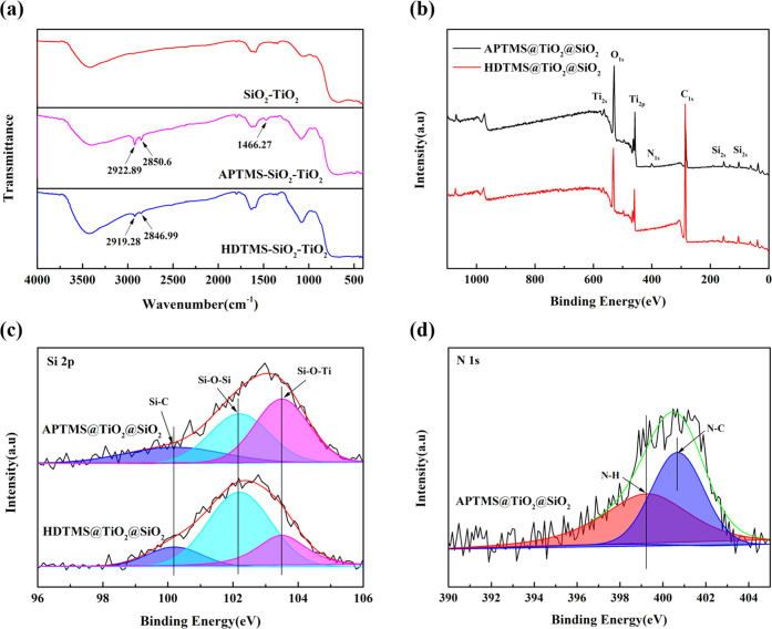
Figure 7 shows the FTIR and XPS spectra of islandlike TiO2@SiO2, APTMS-TiO2@SiO2, and HDTMS-TiO2@SiO2 composites. As seen in Figure 7a, compared with islandlike TiO2@SiO2, the HDTMS-TiO2@SiO2 composite exhibited new peaks at 2918 and 2846 cm–1 assigned to the C–H stretching vibration; the APTMS-TiO2@SiO2 composite exhibited new peaks at 2918 and 2846 cm–1 assigned to the C–H stretching vibration as well as 1466 cm–1 assigned to the C–N band.26 Through the above FTIR results, it could be concluded that the silane coupling agent was grafted on the islandlike TiO2@SiO2 composite. Figure 7b shows representative XPS spectra of the islandlike TiO2@SiO2, APTMS-TiO2@SiO2, and HDTMS-TiO2@SiO2 composite. The obvious peaks of C 1s, O 1s, Ti 2p, and Si 2p appeared in all samples. Among these three samples, only APTMS-TiO2@SiO2 exhibited the characteristic peak of N 1s. The high-resolution XPS spectroscopy is shown in Figure 7c,d. As seen in Figure 7c, there were common peaks at 102.2 and 103.5 eV for the Si 2p spectra of all particles, which could be assigned to Si–O–Si and Si–O–Ti bonds. Compared with the islandlike TiO2@SiO2 composite, the APTMS-TiO2@SiO2 and HDTMS-TiO2@SiO2 composite had a new peak at 100.2 eV, which was attributed to the Si–C bond, indicating the grafted modification of the TiO2@SiO2 composite with silane coupling agent APTMS and HDTMS.27 As seen in Figure 7d, only the APTMS-TiO2@SiO2 composite exhibited N 1s spectra, which could be deconvoluted to two peaks at 399.3 and 400.7 eV. The peaks at 399.3 eV were assigned to the N–H bond, and peaks at 400.7 eV were assigned to the N–C bond, suggesting the presence of APTMS on the surface of the APTMS-TiO2@SiO2 composite.28
Figure 7.
(a) FTIR spectrum of the islandlike TiO2@SiO2, APTMS-TiO2@SiO2, and HDTMS-TiO2@SiO2 composite. (b) Representative XPS spectra of the APTMS-TiO2@SiO2 and HDTMS-TiO2@SiO2 composite. (c, d) High-resolution XPS spectra of Ti 2p and N 1s.
4. Conclusions
The grafted modification SiO2-coated TiO2 composite was prepared by two steps: first, deposition of SiO2 on the surface of TiO2, followed by graft modification of the TiO2@SiO2 composite. The experimental results indicated that the islandlike TiO2@SiO2 composite conducted better printing performance due to the deposition of SiO2 particles on the surface of SiO2 particle homogeneously, increasing the ζ-potential of the TiO2@SiO2 composite to improve the dispersibility of the TiO2@SiO2 composite in the printing formula. Compared with the dense TiO2@SiO2 composite, the surrounding TiO2 particle was partly replaced by SiO2 particle in the islandlike TiO2@SiO2 composite so that the difference of refractive indices was not decreased obviously and a better printing performance was obtained. The presence of Si was confirmed by EDX elemental analysis and XPS and a peak at 980 cm–1 belonging to Si–O was observed in the FTIR, confirming the presence of SiO2 anchored at TiO2 surfaces via Si–O–Ti bonds in the islandlike TiO2@SiO2 composite. The islandlike TiO2@SiO2 composite was then modified by grafting with a silane coupling agent. The hydrophilic modification of the TiO2@SiO2 composite using APTMS contributed to the improvement of dispersibility and printing performance compared with hydrophobic modification using HDTMS. The grafted modification TiO2@SiO2 composites were characterized by FTIR and XPS. The peaks at 2919 and 2846 cm–1 belong to CH2 in the FTIR spectrum and Si–C in the XPS confirmed the silane coupling agent grafted to the TiO2@SiO2 composite. The APTMS-TiO2@SiO2 composite exhibited weather durability, dispersibility, and good printing performance.
Acknowledgments
This work is supported by the Opening Project of China National Textile and Apparel Council Key Laboratory of Natural Dyes, Soochow University, No. SDHY2118, Talent Introduction Program of Minjiang University (MJY20030) and Guided Project of Fujian Province (2021H0056).
The authors declare no competing financial interest.
References
- Maleki H.; Bertola V. TiO2 nanofilms on polymeric substrates for the photocatalytic degradation of methylene blue. ACS Appl. Nano Mater. 2019, 2, 7237–7244. 10.1021/acsanm.9b01723. [DOI] [Google Scholar]
- Wang Y. F.; Yang H. C.; Yun H.; Zhang M.; et al. Crystallization time-induced microstructural evolution and photoelectrochemical properties of ternary Ag@AgBr/TiO2 nanorod arrays. J. Alloys Compd. 2022, 904, 163370 10.1016/j.jallcom.2021.163370. [DOI] [Google Scholar]
- Wang L.; Xie G. Y.; Mi X. A single-step pad-steam cationzation and dyeing process for improving dyeing properties of cotton fabrics. Color. Technol. 2022, 138, 509–521. 10.1111/cote.12608. [DOI] [Google Scholar]
- Goulart S.; Nieves L.; Bernardin A. Sensitization of TiO2 nanoparticles with natural dyes extracts for photocatalysis activity under visible light. Dyes Pigm. 2020, 182, 108654 10.1016/j.dyepig.2020.108654. [DOI] [Google Scholar]
- Hakim L. F.; King D. M.; Zhou Y.; et al. Nanoparticle Coating For Advanced Optical, Mechanical And Rheological Properties. Adv. Funct. Mater. 2007, 17, 3175–3181. 10.1002/adfm.200600877. [DOI] [Google Scholar]
- Wei B.-X.; Zhao L.; Wang T.; et al. Photo-stability of TiO2 particles coated with several transition metal oxides and its measurement by rhodamine-B degradation. Adv. Powder Technol. 2013, 24, 708–713. 10.1016/j.apt.2012.12.009. [DOI] [Google Scholar]
- Zhang Y.; Yin H.; Wang A.; et al. Deposition and characterization of binary Al2O3/SiO2 coating layers on the surfaces of rutile TiO2 and the pigmentary properties. Appl. Surf. Sci. 2010, 257, 1351–1360. 10.1016/j.apsusc.2010.08.071. [DOI] [Google Scholar]
- Gao H.; Qian B.; Wang T.; et al. Cerium Oxide Coating of Titanium Dioxide Pigment to Decrease Its Photocatalytic Activity. Ind. Eng. Chem. Res. 2014, 53, 189–197. 10.1021/ie402539n. [DOI] [Google Scholar]
- Guo J.; Benz D.; Nguyen T.; et al. Tuning the Photocatalytic Activity of TiO2 Nanoparticles by Ultrathin SiO2 Films Grown by Low-Temperature Atmospheric Pressure Atomic Layer Deposition. Appl. Surf. Sci. 2020, 530, 147244 10.1016/j.apsusc.2020.147244. [DOI] [Google Scholar]
- Liu Y.; Ge C.; Min R.; et al. Effects of coating parameters on the morphology of SiO2-coated TiO2 and the pigmentary properties. Appl. Surf. Sci. 2008, 254, 2809–2819. 10.1016/j.apsusc.2007.10.021. [DOI] [Google Scholar]
- Zhang Y.; Yin H.; Wang A.; et al. Evolution of zirconia coating layer on rutile TiO2 surface and the pigmentary property. J. Phys. Chem. Solids 2010, 71, 1458–1466. 10.1016/j.jpcs.2010.07.013. [DOI] [Google Scholar]
- Gao H.; Qiao B.; Wang T. J.; et al. Effects of porous films on the light reflectivity of pigmentary titanium dioxide particles. Appl. Surf. Sci. 2016, 387, 581–587. 10.1016/j.apsusc.2016.06.131. [DOI] [Google Scholar]
- Liang Y.; Yu K.; Xie J.; Wang T.; Zheng Q. High hiding power and weather durability of film-coated titanium dioxide particles with a yolk-shell structure. Colloids Surf., A 2017, 520, 736–742. 10.1016/j.colsurfa.2017.02.046. [DOI] [Google Scholar]
- Wu C.-Y.; Tu K.; Deng J.; et al. Markedly Enhanced Surface Hydroxyl Groups of TiO2 Nanoparticles with Superior Water-Dispersibility for Photocatalysis. Materials 2017, 10, 566. 10.3390/ma10050566. [DOI] [PMC free article] [PubMed] [Google Scholar]
- Zhao J.; Jie Z.; Milanova M.; Warmoeskerken M. Surface modification of TiO2 nanoparticles with silane coupling agents. Colloids Surf., A 2012, 413, 273–279. 10.1016/j.colsurfa.2011.11.033. [DOI] [Google Scholar]
- Wang C.; Mao H.; Wang C.; Fu S. Dispersibility and Hydrophobicity Analysis of Titanium Dioxide Nanoparticles Grafted with Silane Coupling Agent. Ind. Eng. Chem. Res. 2011, 50, 11930–11934. 10.1021/ie200887x. [DOI] [Google Scholar]
- Ukaji E.; Furusawa T.; Sato M.; Suzuki N. The effect of surface modification with silane coupling agent on suppressing the photo-catalytic activity of fine TiO2 particles as inorganic UV filter. Appl. Surf. Sci. 2007, 254, 563–569. 10.1016/j.apsusc.2007.06.061. [DOI] [Google Scholar]
- Singh J.; Gusain A.; Saxena V.; et al. XPS, UV–Vis, FTIR, and EXAFS Studies to Investigate the Binding Mechanism of N719 Dye onto Oxalic Acid Treated TiO2 and Its Implication on Photovoltaic Properties. J. Phys. Chem. C 2013, 117, 21096–21104. 10.1021/jp4062994. [DOI] [Google Scholar]
- Lowenstern J. B.; Pitcher B. W. Analysis of H2O in silicate glass using attenuated total reflectance (ATR) micro-FTIR spectroscopy. Am. Mineral. 2013, 98, 1660–1668. 10.2138/am.2013.4466. [DOI] [Google Scholar]
- Liu F.; Zhi L.; Gu Y.; et al. Synthesis and characterization of a conducting polyaniline/TiO2–SiO2 composites. J. Appl. Polym. Sci. 2013, 130, 2288–2295. 10.1002/app.39425. [DOI] [Google Scholar]
- Song X.; Gao L. Synthesis, characterization, and optical properties of well-defined N-doped, hollow silica/titania hybrid microspheres. Langmuir 2007, 23, 11850–11856. 10.1021/la7019704. [DOI] [PubMed] [Google Scholar]
- Chen Y.; Liu K. Fabrication of Ce/N co-doped TiO2/diatomite granule catalyst and its improved visible-light-driven photoactivity. J. Hazard. Mater. 2017, 324, 139–150. 10.1016/j.jhazmat.2016.10.043. [DOI] [PubMed] [Google Scholar]
- Pinho L.; Mosquera M. J. Photocatalytic activity of TiO2-SiO2 nanocomposites applied to buildings: Influence of particle size and loading. Appl. Catal., B 2013, 134–135, 205–221. 10.1016/j.apcatb.2013.01.021. [DOI] [Google Scholar]
- Kim H. J.; Kang I. G.; Kim D. H.; Choi B. H. Dispersion characteristics of TiO2 particles coated with the SiO2 nano-film by atomic layer deposition. J. Nanosci. Nanotechnol. 2011, 11, 10344–10348. 10.1166/jnn.2011.5011. [DOI] [PubMed] [Google Scholar]
- Zhai L.; Yan W.; Feng P.; et al. Synthesis of TiO2–SiO2/waterborne polyurethane hybrid with amino-siloxane terminated via a sol–gel process. Mater. Lett. 2012, 89, 81–85. 10.1016/j.matlet.2012.08.083. [DOI] [Google Scholar]
- Wang L.; Hu C. Y.; Yan K. L. A one-step inkjet printing technology with reactive dye ink and cationic compound ink for cotton fabrics. Carbohydr. Polym. 2018, 197, 490–496. 10.1016/j.carbpol.2018.05.084. [DOI] [PubMed] [Google Scholar]
- Han Z.; Li P.; Deng Y.; Li H. Reversible and color-variable afterglow luminescence of carbon dots triggered by water for multi-level encryption and decryption. Chem. Eng. J. 2021, 415, 128999 10.1016/j.cej.2021.128999. [DOI] [Google Scholar]
- Zhao H.; Hou L.; Lu Y. Electromagnetic shielding effectiveness and serviceability of the multilayer structured cuprammonium fabric/polypyrrole/copper (CF/PPy/Cu) composite. Chem. Eng. J. 2016, 297, 170–179. 10.1016/j.cej.2016.04.004. [DOI] [Google Scholar]


