Abstract
Bevel-tip needles are commonly utilized in percutaneous medical interventions where a curved insertion trajectory is required. To avoid deviation from the intended trajectory, needle shape sensing and tip localization is crucial in providing the operator with feedback. There is an abundance of previous work that investigate the medical application of fiber Bragg grating (FBG) sensors, but most works select only one specific type of fiber among the many available sensor options to integrate into their hardware designs. In this work, we compare two different types of FBG sensors under identical conditions and application, namely, acting as the sensor for needle insertion shape reconstruction. We built a three-channel single core needle and a seven-channel multicore fiber (MCF) needle and discuss the pros and cons of both constructions for shape sensing experiments into constant curvature jigs. The overall needle tip error is 1.23 mm for the single core needle and 2.08 mm for the multicore needle.
I. Introduction
There exists a wide range of medical procedures that utilize bevel-tip needle insertion to minimize procedure-induced invasion to the body, including but not limited to biopsy, brachytherapy, and prostate surgery [1]–[3]. The bevel-tip is capable of driving the needle in a curved trajectory due to the uneven force applied to the asymmetric needle body. However, uncertain conditions during the insertion such as tissue obstruction, movement of patient, or practitioner error may deviate the needle from its intended trajectory. This will result in complications such as tissue irritation during repetitive reinsertions when readjusting the position of the needle and accidental damage of nearby sensitive anatomical structures [4]. Guidance solutions are therefore imperative to minimize such risks during the insertion process by means of providing the practitioner with constant feedback on the needle location [5]. A conventional method utilizes real-time imaging modalities such as ultrasound imaging [6], [7] and MRI [8], [9] to track the needle’s trajectory during the insertion process. An alternative approach uses needles with built-in FBG sensors [10]. These FBG fibers embedded into the needle are optical sensors capable of detecting locally induced strain at specific locations throughout the fibers, referred to as the “active areas”, from the reflected optical wavelength at the active areas. From these FBG sensor readings, the current shape of the needle can be accurately reconstructed and determined without being able to visually observe the inserted portion. Another advantage of the FBG sensor is their compatibility with MRI, so that this shape-sensing method can be utilized in combination with the aforementioned imaging modalities.
Currently, standardized bevel-tip needles integrated with FBG sensors cannot be readily found on the market, and thus this apparatus must be built by the individuals according to their own needs and specifications. With this flexibility, optimization of the needle hardware design becomes an important consideration for the development of any FBG fiber shape-sensing needles. There are several previous works that investigate the optimization of needle, ranging from the placement of fibers across the needle cross section for best shape reconstruction to compensation experiments for inherent imperfections of the fibers [11]–[16]. These efforts mostly propose a single needle hardware design and discuss in depth the optimization methods of such design.
With the advancement of optical sensor fabrication technology, there are an emerging number of novel variants of FBG sensor options. In this paper, we fabricated two needles with identical form factors and similar sensor structure but using two different variants of FBG sensors: one using single-core FBGs, the other with a multicore FBG [17], [18]. To detect a three-dimensional shape, at least two independent channels are required within one cross-section. In our needle design, we incorporated an additional third channel to perform temperature compensation. The two needles realize an identical channel orientation, with the three channels laying on the same circle and 120° degree apart from one another. A noteworthy difference lies in the radial distance between the channels and the core of the needle.
This distance is larger for the single core needle since it relies on an inner stylet to hold the individual fibers in place, whereas the multicore has the desired distribution embedded in the FBG already. For the multicore needle, the wavelength data of an additional channel located in the center of the fiber is collected, and this center core is only used for temperature compensation. This additional physical core channel allows for novel methods of performing temperature compensation on the FBG wavelength shift data.
II. Needle Construction
We fabricated two needles with identical form factors that integrates single core FBG and multicore FBG. Both needles are 200mm in length, and each have four sensing locations, referred to as active areas (AA). (Fig. 1)
Fig.1:

The locations of the four active areas along the needle, measured from the needle bevel tip
A. Three-channel Single-Core Fiber Needle
For the needle to reconstruct its three-dimensional bending shape, it must have multiple sensors to collect strain data from different directions. Our needle integrates three single-core fibers (80-micron cladding diameter, Technica Optical Components LLC, Atlanta, GA) distributed evenly across the cross-section of the needle. (Fig. 2) To anchor the fibers, we manufactured an inner stylet with three grooves, and glue (Loctite AA 3322, Henkel, Rocky Hill, CT) the fibers onto this inner stylet. This assembly step took more than four hours since we must wait for the 3–4 mm wide glue segment to dry before applying the next segment of glue, ensuring completely adherence of the fiber to the stylet. This step is repeated for all three fibers. This fiber-stylet assembly is then placed in a nitinol tube for protection before finally mounted into the outer 18-gage bevel tip needle.
Fig.2:
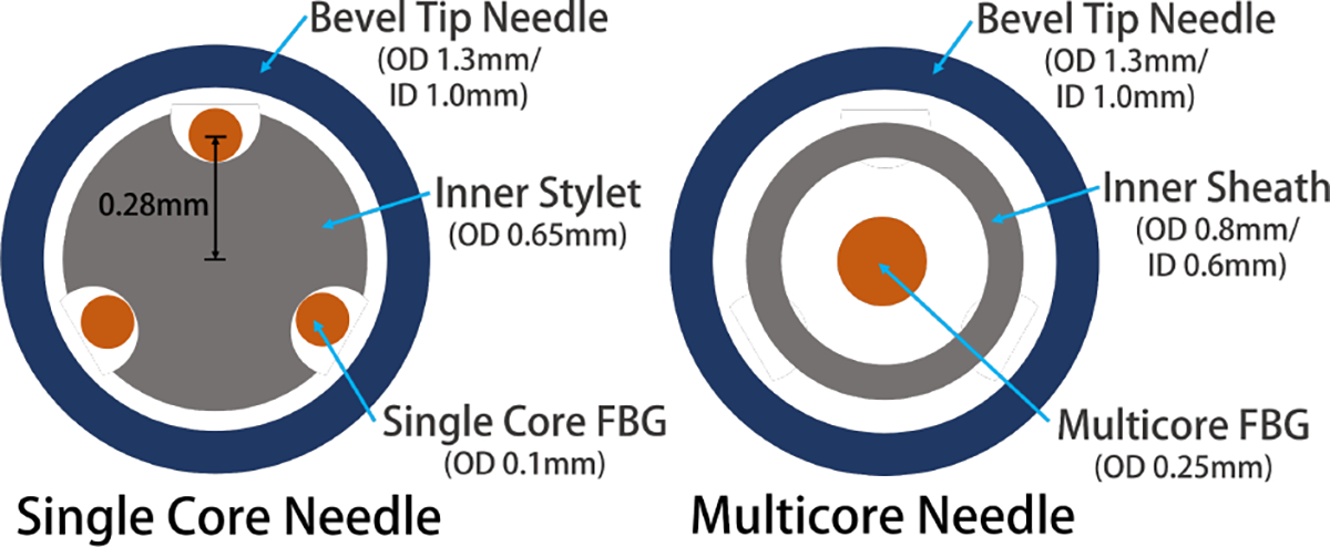
Cross section of the mechanical design of the single core needle (left) and multicore needle (right)
During the mounting process, we ensure that one of the three fibers aligns with the bevel tip of the outer needle, while the other two flanks this fiber symmetrically on both sides in reference to the central plane of the needle.
B. Multicore Fiber Needle
The multicore needle only requires a single fiber with seven separate channels engraved (125-micron cladding diameter, Fujikura America, Sunnyvale, CA) (Fig. 3). Compared with the single-core needle with three different fibers, an additional inner stylet was not required to ensure the even separation of the fibers, and thus we directly place the multicore fiber into its protective nitinol tube (Fig. 2). To anchor the fiber, we glue the two ends of the fiber onto the nitinol tube. Lastly, analogous to the fabrication to the single-core needle, we mount the nitinol-fiber assembly into the outer 18-gage bevel tip needle.
Fig.3:
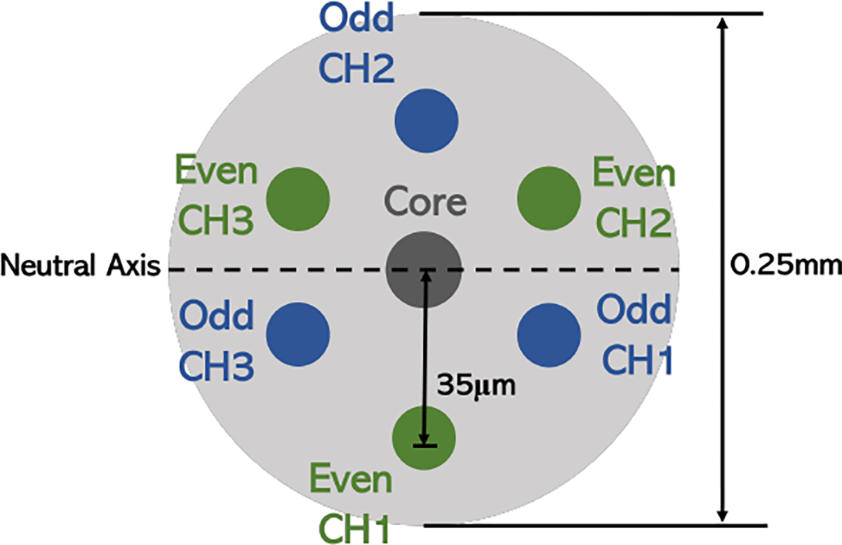
Cross-section of the multicore FBG sensor with 7 channels embedded. In this experiment, we collected data from the core channel and three EVEN radial channels 120° degrees apart (green)
III. Models and Methods
A. FBG Sensor Model
FBG sensors are optical sensors that can detect curvature due to its capability of perceiving strain. The sensor does so by reflecting light at a peak wavelength (called the “Bragg wavelength”), and the change of this wavelength is related to the change in strain and temperature applied to the fiber by such:
| (1) |
where is the fiber’s Bragg wavelength when unstrained, and are respectively the strain and temperature sensitivity coefficients.
In order to relate the shift in FBG wavelength directly to the curvature sensed, we use the Euler-Bernoulli beam theory, which stipulates the relationship of a strain to the curvature of a beam as such:
| (2) |
where is the distance from the neutral bending plane of the beam.
After first eliminating the effect of temperature from the FBG wavelength data, cascading these two equations that explains the linear relationship between wavelength shift – strain (Eq.1) and strain – curvature (Eq.2), we derive the single linear expression as such:
| (3) |
In developing a shape sensing needle, deriving the calibration coefficients to estimate induced curvature from detected wavelength shifts is a requirement. For a three-channel needle, the 2×3 calibration matrix entries consist of these coefficients, where the columns represent the three channels and the rows represent the two vertical bending planes of a three-dimensional needle. A single calibration matrix will be derived per AA (Eq.3).
B. Temperature Compensation
The wavelength shift of a FBG fiber is induced by two elements: change in strain and change in temperature [19]. Since information about the insertion condition might not be always readily available, we must incorporate a method of negating the effect caused by the change in temperature in our signal processing model.
We assume the channels’ corresponding AAs to experience the same temperature at any point of time, and thus temperature should induce identical offsets in the wavelength shift for all channels within an AA. We, thus, deduct the common mode of the three channels from their respective FBG wavelength shift as this in effect takes away the common influence these channels are all experiencing, and the remaining wavelength shift shall only account for the that caused by strain [19].
For the multicore needle, in addition to the conventional common-mode deduction method, an alternative solution is to directly deduct the core channel FBG wavelength shift. Since the core channel lies on the neutral bending axis, this core should not experience any strain related to the curving of the needle. Therefore, any shift of this channel’s FBG wavelength data should be caused solely by the change in temperature. Assuming identical temperature experienced on all the channels, we take away this same amount of temperature induced wavelength shift from all the radial channels.
C. Shape Reconstruction Model
After obtaining the curvature readings from the FBG wavelength shift data at the different locations, we reconstruct the compete needle shape using a constant curvature model with Lie algebra [20], [21]. The model is as follows:
| (4) |
where , and represent the curvature along the local - and -axes (bending), and -axis (torsion) respectively; denotes the 3D rotation matrix representing the orientation of the local coordinate frame at each point along the needle; and denotes the arclength of the needle, where is the insertion distance. The operation represents a 3D vector associated with a 3×3 skew-symmetric matrix .
We then obtain the needle shape by integrating :
| (5) |
where .
IV. Experimental Setup
A. Characterization
After constructing the needles, validating that the FBG sensors are functioning normally is imperative prior to advancing to subsequent experiments. There are several criteria to ensuring behavior of the FBG is as expected: a) Checking for the normal distribution of all the samples data points during one single collection, b) Symmetric behavior between the two fibers that are placed symmetrically with regards to the neutral plane, and c) linearity of FBG wavelength shift response to curvature.
This verification experiment is designed as follows: the needle is initially positioned horizontally with the bevel tip fixed on a horizontal bar. The bar is placed on top of a scale (GC2502, Sartorius, Göttingen, Germany) to ensure horizontal placement of the needle. (Fig. 4) The other end of the needle is then bent vertically downwards for ten steps via a linear stage (M-400, Dover Motion, Boxborough, MA) of 1.5mm displacements (load), and then slowly released back to its initial horizontal position again across ten 1.5mm increments (unload). After the actuation of each step, a sample size of 200 FBG wavelength shift data points are collected to mitigate the effect of FBG sensor noise. This load-unload cycle is repeated for five trials to ensure significance of the collected data. We repeat this experiment for three rotations with a rotary stage (B5990TS, Velmex, Inc., Bloomfield, NY): 0°, 120°, and 240°, so that each rotation would position one of the fibers directly on top of the neutral bending plane leaving the other two symmetric about said plane. These two symmetric fibers should exhibit similar behavior in their wavelength shifts, and thus provide insight to the presence of significant internal twist of the fibers causing a deviation from the expected symmetric response in their wavelength shifts [22].
Fig.4:
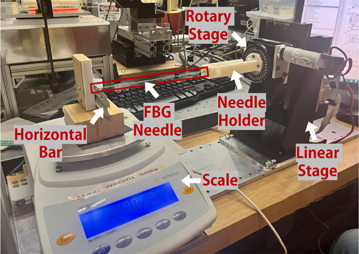
Experimental Set-up for Characterization
B. Calibration and Validation
After verifying proper functionality of the fibers, the most important step of developing a shape sensing needle is to empirically derive the calibration matrices to correlate detected FBG wavelength shifts to the curvature experienced by the needle [14]. We designed a calibration jig with six known constant curvature grooves (κ = 0.5/1.6/2.0/2.5/3.2/4.0 (1/m)), so that all AAs on a fiber experience the same curvature when inserted into the jig. (Fig. 5) Five insertion trials were performed per groove to ensure the significance of results. We integrated an additional straight groove in the calibration jig to determine a baseline unstrained FBG wavelength which will be subtracted from all the raw wavelengths collected in the other curved grooves to calculate the FBG wavelength shift. A linear regression is then performed between the calculated wavelength shifts for each active area and the known curvature values (Eq.3), resulting in a calibration matrix that correlates the FBG wavelength shift to the curvature.
Fig.5:
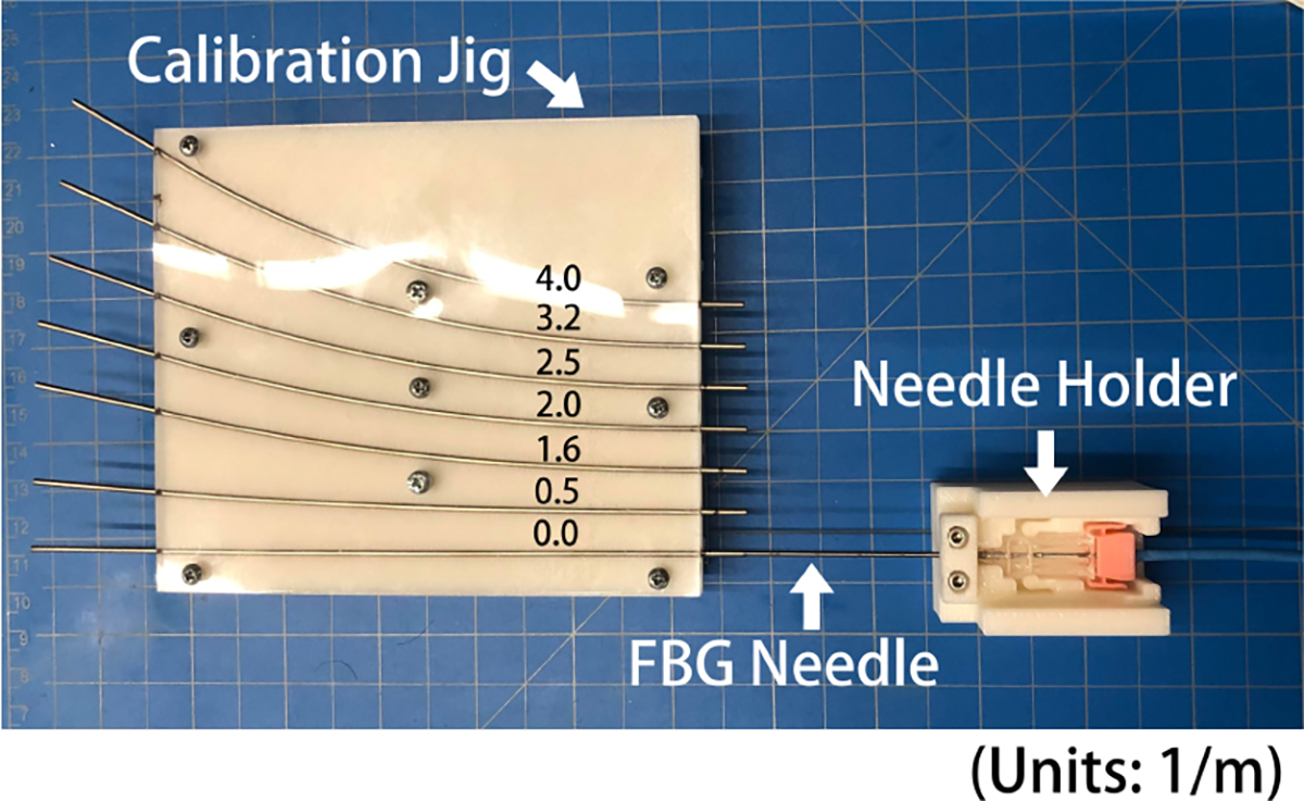
Experimental Set-up for Calibration, the needle holder jig is to ensure level insertion of the needle into the grooves of the calibration/validation jig
After we obtain the calibration matrices, we want to validate the performance of these matrices with a new set of test data. For this, we designed another validation jig with five grooves (κ = 0.25/0.8/1.0/1.25/3.125 (1/m)) that all have different curvatures from the calibration jig. Again, five insertion trials were performed per groove. We then calculate the predicted curvature for each active area by multiplying the FBG wavelength shift by the calibration matrix.
V. Results
A. Characterization
We first verified the normal distribution of all the data points collected across a single insertion (Fig. 6). Then, we plotted the FBG wavelength shift data of the three channels at every AA against the deflection distance from the unbent location (Fig. 7).
Fig.6:
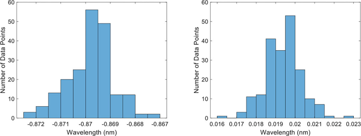
Histogram of FBG wavelength data sample for single core needle (left) and multicore needle (right)
Fig.7:
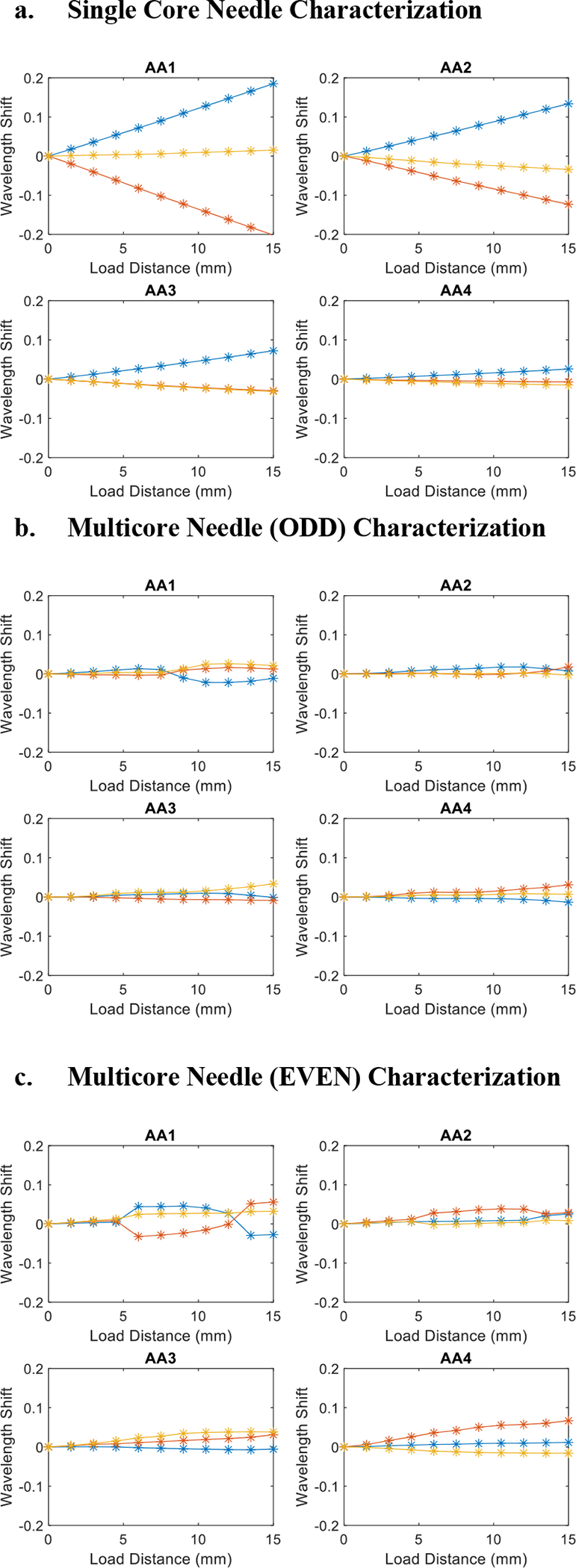
Plot of characterization results for single core needle(a), multicore needle ODD channels(b), and multicore needle EVEN channels(c)
As shown in Fig. 7a, the single-core needle exhibits a linear behavior throughout the different deflection distances, additionally with the two channels (indicated by the blue and red lines) situated at opposite locations from the neutral plane exhibiting symmetric behavior. Notably, we observe that given the same deflection distance, the magnitudes of wavelength shift increase as the distance from the needle tip increases. AA1, furthest from the needle tip, experiences the largest wavelength shifts while AA4, closest to the needle tip, detected noticeably smaller wavelength shifts. This coincides with the ground truth of the bent shape where cross sections furthest away from the needle tip experience the biggest curvature.
For the multicore needle characterization, we observed certain phenomena that necessitated the further investigation for the data processing algorithm and hardware design change. First, the overall sensitivity of the multicore needle is lower compared with the single-core needle as evidenced by the smaller wavelength shift magnitudes of same deflection distances. This is within expectation since the multicore fiber has a smaller radial distance between the neutral bending plane and the radial channels from which we have selected to collect data. The most significant abnormality in the multicore characterization result is the occasional nonlinear behavior, most heavily observed in the first active area (Fig. 7b). However, it exhibits a generally linear behavior across the channels, and since the majority of the multicore FBG sensor appears proportional to the curvature experienced by the external needle, we are confident enough to affirm the normal functionality of the sensor and continue with the calibration and validation experiments.
Notably, we repeated the characterization experiment for both the ODD channels (Fig. 7b) and EVEN channels (Fig. 7c) of the multicore needle. We can observe from Fig. 7b and Fig. 7c that the FBG wavelength shift signal of the EVEN channel has a larger magnitude than that of the ODD channel, and thus we selected to collect data from the EVEN channels in our calibration experiments.
B. Calibration and Validation
For the calibration and validation experiments, we first generated the calibration matrices for the two needles (Fig. 8).
Fig.8:
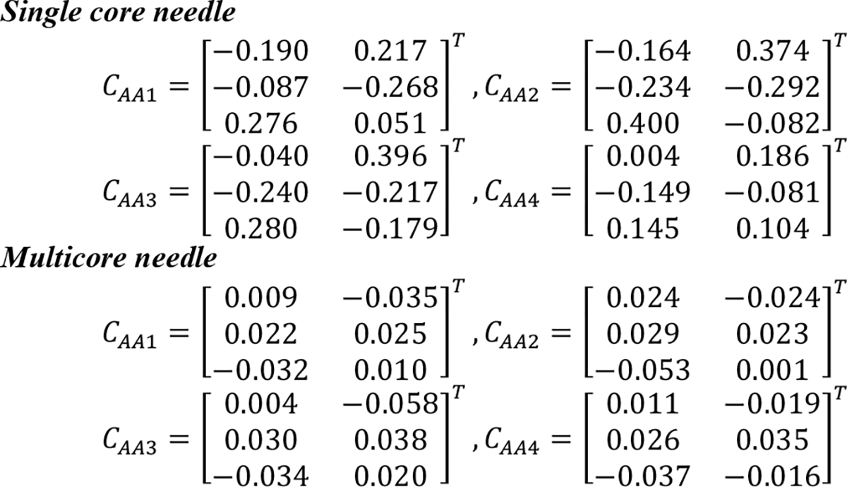
Calibration Matrices for the single core needle and multicore needle
Using these calibration matrices, we then calculated the sensed curvatures from the FBG wavelength shift data collected in the validation jig, and finally reconstructed the entire curve based on these sensor readings. We characterized these reconstruction results with four error metrics:
Tip Error (TE): the needle tip location error from the ground truth
| (6) |
Root Mean Square Error (RMSE): the RMS error of the needle locations along the entire constructed shape
| (7) |
In-Plane Error (IPE): the shape error in the natural bending plane of the bevel-tip needle
| (8) |
Out-of-Plane Error (OPE): the needle error on the plane vertical to the bending plane.
| (9) |
The reconstruction results are shown in Fig. 9. We plotted the needle shape reconstruction derived from the constant curvature model illustrated in Eq.4 and Eq.5 against the ground truth curvature of the jig groove. We aligned the start point of these two plots and analyzed the tip deflection as well as error along the needle body. A quantitative breakdown of the error for the different curves are shown in Table 1, represented by the mean and standard deviation of the errors for a given curve across the five trials.
Fig.9:
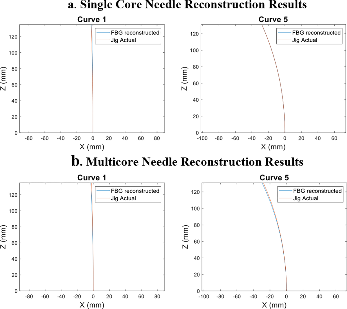
Examples of needle eeconstruction results of the smallest and largest curvature validation curve for the single core needle(a) and multicore needle(b). The blue line represents the FBG detected needle shape, while the orange line is the ground truth of the validation jig groove
Table 1:
Comparison of error results for the single core/multicore needle
| Curve | Needle | TE (mm) | RMSE (mm) | IPE (mm) | OPE (mm) |
|---|---|---|---|---|---|
| 1 | Single | 0.77±0.08 | 0.34±0.03 | 0.26±0.03 | 0.26±0.03 |
| Multi | 1.15±0.47 | 0.51±0.21 | 0.38±0.16 | 0.38±0.16 | |
| 2 | Single | 1.67±0.10 | 0.75±0.04 | 0.56±0.03 | 0.56±0.03 |
| Multi | 2.36±0.53 | 1.06±0.24 | 0.79±0.18 | 0.79±0.18 | |
| 3 | Single | 1.69±0.02 | 0.76±0.01 | 0.56±0.01 | 0.56±0.01 |
| Multi | 2.97±0.45 | 1.33±0.20 | 0.99±0.15 | 0.99±0.15 | |
| 4 | Single | 1.88±0.05 | 0.84±0.02 | 0.63±0.02 | 0.63±0.02 |
| Multi | 2.51±0.23 | 1.13±0.10 | 0.84±0.08 | 0.83±0.08 | |
| 5 | Single | 0.13±0.12 | 0.06±0.05 | 0.04±0.04 | 0.04±0.04 |
| Multi | 1.42±0.13 | 0.64±0.06 | 0.47±0.04 | 0.46±0.04 | |
| Total | Single | 1.23±0.69 | 0.55±0.31 | 0.41±0.23 | 0.41±0.23 |
| Multi | 2.08±0.79 | 0.93±0.35 | 0.70±0.26 | 0.69±0.26 |
VI. Discussion
From the reconstruction results, we observe that the single-core needle produces more accurate shape sensing results under our current experimental conditions. We compared the overall errors for the two needles across all curvatures and trials and concluded that the single core needle provided better results across the four error categories. (TE: p < 0.05, RMSE: p < 0.05, IPE: p < 0.05, OPE: p < 0.05) In this section, we discuss the possible sources of error of the two needles and the pros and cons of the selection between the two types of sensors. We break down the analysis into two aspects: the signal processing of the wavelength data and the hardware design of the needle.
A. Signal Processing
To simultaneously collect data from up to four channels, we selected the SM130 interrogator (Micron Optics, Roanoke, VA) as our interrogator for reading in the FBG wavelength shift data for both needles. Furthermore, as shown in Fig. 7, the magnitude of the FBG wavelength shift for the multicore is smaller than the data from the single-core needle.
A higher resolution interrogator might be necessary in collecting data from the multicore needle to reduce the signal-to-noise ratio. We leave the investigation of the effect our interrogator has on the results by repeating this experiment with higher precision equipment as a future work.
We then compared the accuracy of reconstruction for the multicore needle using the two temperature compensation methods (common-mode subtraction and core channel subtraction). We did not observe statistically significant differences of the four types of error across the different trials and curvatures for both methods. (TE: p = 0.26, RMSE: p = 0.27, IPE: p = 0.25, OPE: p = 0.25), thus we conclude neither of the temperature compensation methods distinctively outperform the other.
We further verified this by plotting the FBG wavelength shift of the core channel against the common mode of the three radial channels. (Fig. 10) We see these two signals across the four active areas all exhibit similar behavior, and thus we can assume the fluctuation for both the core channel signal and common mode signal is caused by the temperature variation.
Fig.10:
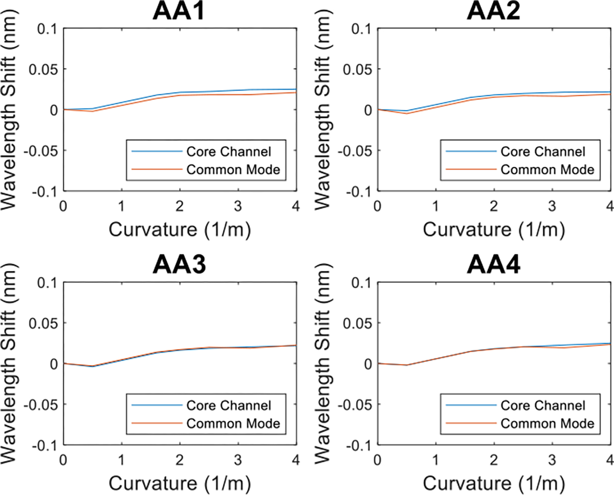
Examples of the comparison between FBG wavelength shift data for the multicore needle core channel (blue) and common mode of the three radial channels (orange) of the first two AAs
B. Needle Hardware Design
An inherent difference in the two types of fiber is the radial distance between the centerline of the needle and the shape-sensing channels. This distance is larger for the single core needle due to the diameter of the inner stylet, whereas the channels of the multicore FBG has a pre-determined radius dictated by the sensor fabrication. According to beam theory, the strain (Eq.2) induced on a localized area increases as it moves away from the neutral bending plane. The geometry explains the single core needle’s larger wavelength shift when the two needles are experiencing the same external curvature. The optimal operating curvature ranges for the two types of FBG sensors thus likely be different and should be validated in future experiments that perform the constant curvature jig insertion across more variable curvatures, such as polynomial or exponential curves.
Another hypothesis for the error discrepancies could lie in the hardware construction. With all the channels prefabricated onto one single multicore fiber, an inner stylet was not required to hold the three channels in their desired positions. Without this center structure to anchor the FBG, there is a possibility for FBG fluctuation inside the inner sheath. This causes two possible problems: FBG twist and the interplay between the fiber and inner sheath.
The internal twisting of the multicore FBG fiber is a probable explanation for the observed nonlinearities in AA1 during the characterization experiments [23], [24]. Instead of having the entire inserted FBG fiber vertical to the cross section of the needle, there may have been segments of the fiber twisted. This twist would change the relative orientation of these channels against the neutral bending plane and would result in incongruent FBG readings compared to the un-twisted segments. A possible solution to this phenomenon is to incorporate twist compensation as a part of the FBG signal processing method. By performing this extra step, the effect of the torsional shift of the channels could be negated by post-processing of the FBG wavelength shift data.
The other problem arising from the lack of inner stylet is that this hollow structure inadvertently introduces more space in between the layers of the needle. Since the multicore fiber is only anchored at the two ends of the inner sheath, the curvature experienced by the multicore fiber may differ from the exerted curvature on the needle tubing yielding an erroneous curvature measurement. Another point of focus for the future integration of multicore fibers into our shape sensing needles is the optimization of the hardware design and the method with which we attach the FBG fiber to the needle body.
Even though the single-core needle yielded better reconstruction accuracy under our specific experimental setup, there are still respective advantages from both types of sensors. The single-core needle has a well-defined inner stylet that purports the three channels, serves as a sufficient anchor site and provides structural integrity. The single-core fiber also utilizes cheaper FBG sensors. Its disadvantages are the bulkiness of the sensor instruments and the difficult and time-consuming fabrication process.
The multicore needle, on the other hand, requires only one fiber and no inner stylet, can thus be integrated into a smaller diameter needle and provides opportunities for developing thinner and more flexible needles. The fabrication process is also greatly simplified without having to apply glue throughout the entire needle body. The challenge of the multicore in its current construction is its lower sensitivity response when experiencing the same induced curvature. Further complications may also arise from the twist of the multicore fiber and the interplay between the partially anchored needle layers.
VII. Conclusion
This work provides an introductory analysis between two types of FBG sensor fibers used in shape-sensing needle applications. Even though the accuracy of the single core needle exceeds that of its multicore counterpart, it does not negate the prospects of the latter in medical applications. The multicore FBG still remains a strong candidate with various distinct advantages such as reduced number of physical fibers, ease of fabrication, and more channels available for information collection. Our future work will focus on investigating the effect of interrogator precision and the effect interplay between the needle layers on shape reconstruction errors. Our future efforts will expand experimental settings to encompass a wider spectrum of conditions such as curvature range and larger fluctuation of temperature to determine the optimal operation range for both needles. We will continue to optimize the signal processing methods and hardware designs of both needles with the goal of further improving the accuracy and precision of needle shape reconstruction with FBG sensors.
Acknowledgment
We thank Aabhas Jain, Aryan Sabet Payman, Yanzhou Wang, and Yansheng Xu, who have all contributed to this work.
Research supported by the National Institutes of Health under Grant R01CA235134.
Contributor Information
Alexandra Cheng, Johns Hopkins University, Department of Biomedical Engineering, Baltimore, Maryland 21218 USA.
Dimitri A. Lezcano, Johns Hopkins University, Department of Mechanical Engineering, Baltimore, Maryland 21218 USA
Jin Seob Kim, Johns Hopkins University, Department of Mechanical Engineering, Baltimore, Maryland 21218 USA.
Iulian I. Iordachita, Johns Hopkins University, Department of Mechanical Engineering, Baltimore, Maryland 21218 USA.
REFERENCES
- [1].Okazawa S, Ebrahimi R, Chuang J, Salcudean SE, and Rohling R, “Hand-Held Steerable Needle Device,” IEEE/ASME Transactions on Mechatronics, vol. 10, no. 3, pp. 285–296, Jun. 2005, doi: 10.1109/TMECH.2005.848300. [DOI] [Google Scholar]
- [2].Matlaga BR, Eskew LA, and McCullough DL, “Prostate biopsy: indications and technique.,” J Urol, vol. 169, no. 1, pp. 12–9, Jan. 2003, doi: 10.1097/01.ju.0000041828.84343.53. [DOI] [PubMed] [Google Scholar]
- [3].Pernar CH, Ebot EM, Wilson KM, and Mucci LA, “The Epidemiology of Prostate Cancer,” Cold Spring Harb Perspect Med, vol. 8, no. 12, p. a030361, Dec. 2018, doi: 10.1101/cshperspect.a030361. [DOI] [PMC free article] [PubMed] [Google Scholar]
- [4].Loeb S, Carter HB, Berndt SI, Ricker W, and Schaeffer EM, “Complications After Prostate Biopsy: Data From SEER-Medicare,” Journal of Urology, vol. 186, no. 5, pp. 1830–1834, Nov. 2011, doi: 10.1016/j.juro.2011.06.057. [DOI] [PMC free article] [PubMed] [Google Scholar]
- [5].Glozman D and Shoham M, “Image-Guided Robotic Flexible Needle Steering,” IEEE Transactions on Robotics, vol. 23, no. 3, pp. 459–467, Jun. 2007, doi: 10.1109/TRO.2007.898972. [DOI] [Google Scholar]
- [6].Adebar TK, Fletcher AE, and Okamura AM, “3-D Ultrasound-Guided Robotic Needle Steering in Biological Tissue,” IEEE Trans Biomed Eng, vol. 61, no. 12, pp. 2899–2910, Dec. 2014, doi: 10.1109/TBME.2014.2334309. [DOI] [PMC free article] [PubMed] [Google Scholar]
- [7].Shahriari N, Roesthuis RJ, van de Berg NJ, van den Dobbelsteen JJ, and Misra S, “Steering an actuated-tip needle in biological tissue: Fusing FBG-sensor data and ultrasound images,” in 2016. IEEE International Conference on Robotics and Automation (ICRA), May 2016, pp. 4443–4449. doi: 10.1109/ICRA.2016.7487644. [DOI] [Google Scholar]
- [8].Seifabadi R, Gomez EE, Aalamifar F, Fichtinger G, and Iordachita I, “Real-time tracking of a bevel-tip needle with varying insertion depth: Toward teleoperated MRI-guided needle steering,” in 2013. IEEE/RSJ International Conference on Intelligent Robots and Systems, Nov. 2013, pp. 469–476. doi: 10.1109/IROS.2013.6696393. [DOI] [Google Scholar]
- [9].Su H, Zervas M, Cole GA, Furlong C, and Fischer GS, “Real-time MRI-guided needle placement robot with integrated fiber optic force sensing,” in 2011. IEEE International Conference on Robotics and Automation, May 2011, pp. 1583–1588. doi: 10.1109/ICRA.2011.5979539. [DOI] [Google Scholar]
- [10].Roesthuis RJ, van de Berg NJ, van den Dobbelsteen JJ, and Misra S, “Modeling and steering of a novel actuated-tip needle through a soft-tissue simulant using Fiber Bragg Grating sensors,” in 2015. IEEE International Conference on Robotics and Automation (ICRA), May 2015, pp. 2283–2289. doi: 10.1109/ICRA.2015.7139502. [DOI] [Google Scholar]
- [11].Zhou J, Cai Z, Zhao P, and Tang B, “Efficient Sensor Placement Optimization for Shape Deformation Sensing of Antenna Structures with Fiber Bragg Grating Strain Sensors,” Sensors, vol. 18, no. 8, p. 2481, Aug. 2018, doi: 10.3390/s18082481. [DOI] [PMC free article] [PubMed] [Google Scholar]
- [12].Al-Ahmad O, OURAK M, van Roosbroeck J, Vlekken J, and vander Poorten EB, “Improved FBG-Based Shape Sensing Methods for Vascular Catheterization Treatment,” IEEE Robot Autom Lett, pp. 1–1, 2020, doi: 10.1109/LRA.2020.3003291. [DOI] [Google Scholar]
- [13].Kim JS, Chatrasingh M, Kim S, Suthakorn J, and Iordachita II, “Fiber Bragg Grating based needle shape sensing for needle steering system: Evaluation in inhomogeneous tissue,” in 2017. IEEE SENSORS, Oct. 2017, pp. 1–3. doi: 10.1109/ICSENS.2017.8234074.29780437 [DOI] [Google Scholar]
- [14].Zhang L et al. , “A New Method For Fiber Bragg Grating Based Needle Shape Sensing Calibration,” in 2019. IEEE International Conference on Robotics and Biomimetics (ROBIO), Dec. 2019, pp. 1953–1958. doi: 10.1109/ROBIO49542.2019.8961717. [DOI] [Google Scholar]
- [15].C. A. Lehocky, Yixing Shi, and C. N. Riviere, “Hyper- and viscoelastic modeling of needle and brain tissue interaction,” in 2014. 36th Annual International Conference of the IEEE Engineering in Medicine and Biology Society, Aug. 2014, pp. 6530–6533. doi: 10.1109/EMBC.2014.6945124. [DOI] [PMC free article] [PubMed] [Google Scholar]
- [16].Idrisov R, Floris I, Rothhardt M, and Bartelt H, “Characterization and calibration of shape sensors based on multicore optical fibre,” Optical Fiber Technology, vol. 61, p. 102319, Jan. 2021, doi: 10.1016/j.yofte.2020.102319. [DOI] [Google Scholar]
- [17].Lai T, Cheng P, Yan C, Li C, Hu W, and Yang M, “2D and 3D Shape Sensing Based on 7-Core Fiber Bragg Gratings,” Photonic Sensors, vol. 10, no. 4, pp. 306–315, Dec. 2020, doi: 10.1007/s13320-020-0579-0. [DOI] [Google Scholar]
- [18].Lu Y, Lu B, Li B, Guo H, and Liu Y, “Robust Three-Dimensional Shape Sensing for Flexible Endoscopic Surgery Using Multi-Core FBG Sensors,” IEEE Robot Autom Lett, vol. 6, no. 3, pp. 4835–4842, Jul. 2021, doi: 10.1109/LRA.2021.3067279. [DOI] [Google Scholar]
- [19].Issatayeva A, Amantayeva A, Blanc W, Molardi C, and Tosi D, “Temperature compensation of the fiber-optic based system for the shape reconstruction of a minimally invasive surgical needle,” Sens Actuators A Phys, vol. 329, p. 112795, Oct. 2021, doi: 10.1016/j.sna.2021.112795. [DOI] [Google Scholar]
- [20].Kim JS, Guo J, Chatrasingh M, Kim S, and Iordachita I, “Shape determination during needle insertion With curvature measurements,” in 2017. IEEE/RSJ International Conference on Intelligent Robots and Systems (IROS), Sep. 2017, pp. 201–208. doi: 10.1109/IROS.2017.8202158. [DOI] [Google Scholar]
- [21].Lezcano DA, Iordachita II, and Kim JS, “Lie-Group Theoretic Approach to Shape-Sensing Using FBG-Sensorized Needles Including Double-Layer Tissue and S-Shape Insertions,” IEEE Sens J, vol. 22, no. 22, pp. 22232–22243, Nov. 2022, doi: 10.1109/JSEN.2022.3212209. [DOI] [PMC free article] [PubMed] [Google Scholar]
- [22].Song K, Lezcano DA, Sun G, Seob Kim J, and Iordachita II, “Towards Automatic Robotic Calibration System for Flexible Needles with FBG Sensors,” in 2021. International Symposium on Medical Robotics (ISMR), Nov. 2021, pp. 1–7. doi: 10.1109/ISMR48346.2021.9661542. [DOI] [PMC free article] [PubMed] [Google Scholar]
- [23].Floris I, Madrigal J, Sales S, Calderón PA, and Adam JM, “Twisting compensation of optical multicore fiber shape sensors for flexible medical instruments,” in Optical Fibers and Sensors for Medical Diagnostics and Treatment Applications XX, Feb. 2020, p. 41. doi: 10.1117/12.2543783. [DOI] [Google Scholar]
- [24].Guo Q, Li Z, Liu Q, and Wang H, “Twist Angle Compensation for Three Dimensional Real-Time Shape Sensing Method Based on Multi-Core Optical Fiber,” in 2020. 12th International Conference on Measuring Technology and Mechatronics Automation (ICMTMA), Feb. 2020, pp. 402–406. doi: 10.1109/ICMTMA50254.2020.00094. [DOI] [Google Scholar]


