Abstract
Approximately 1–2% of the reported tuberculosis (TB) cases have skeletal system problems, particularly spinal TB. The complications of spinal TB involve the destruction of vertebral body (VB) and intervertebral disc (IVD) which consequently leads to kyphosis. This work aimed at utilizing different technologies to develop, for the first time, a functional spine unit (FSU) replacement to mimic the structure and function of the VB and IVD along with a good ability to treat spinal TB. 3D-printed scaffolds with different porous patterns (hexagonal or grid) were fabricated from biocompatible acrylonitrile butadiene styrene, and polylactic acid to replace damaged VB and IVD, respectively. The VB scaffold is filled with gelatine-based semi-IPN hydrogel containing mesoporous silica nanoparticles loaded with two antibiotics, rifampicin and levofloxacin, to act against TB. The IVD scaffold incorporates a gelatin hydrogel loaded with regenerative platelet-rich plasma and anti-inflammatory simvastatin-loaded mixed nanomicelles. The obtained results confirmed the superior mechanical strength of both 3D-printed scaffolds and loaded hydrogels as compared to normal bone and IVD with high in vitro (cell proliferation, anti-inflammation and anti-TB), and in vivo biocompatibility profiles. Moreover, the custom-designed replacements have achieved the expected prolonged release of antibiotics up to 60 days. Given the promising study findings, the utilization of the developed drug-eluting scaffold system can be extrapolated to treat not only spinal TB but also to resolve diverse backbone/spine problems that need a critical surgical process including degenerative IVD and its consequences like atherosclerosis, sliding or spondylolisthesis and severe traumatic bone fracture.
An illustration of the fabrication steps for developing of functional spine unit (FSU) replacement implant using a triple strategy to mimic vertebral body (VB) and intervertebral disc (IVD) structure for the treatment of spinal tuberculosis (TB).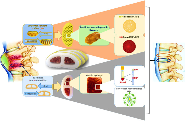
1. Introduction
Spinal tuberculosis (TB) disorders and its complications have affected a huge number of people all over the world and require a great effort and healthcare taxes to be overcome.1 Kyphosis of the backbone, spondylitis and rheumatoid occur due to the destruction of the vertebral body (VB) after infection with TB bacteria.2 Spreading of tuberculous bacilli to intervertebral disc (IVD) space results in many diseases: discitis, osteomyelitis and a kyphotic deformity (Pott's disease). Pott's syndrome is considered a threat of kyphosis due to thoracic infection including more than two vertebrae, and it has many consequences such as dislocation, buckling and endplate deformation.3
Treatment requires complicated surgical processes, medications, and fixations using vertebroplasty and kyphoplasty. The steps of surgical process include laminectomy and laminotomy, abscess evacuation, and fusion. The medications involve oral administration of two lines of antibiotics cocktail lasting for six months.3–5 Vertebroplasty and kyphoplasty are surgical procedures using a medical device and materials that are used to treat vertebral compression fractures commonly associated with osteoporosis, trauma, or tumors.6 As per neurosurgeons' point of view, any vertebroplasty can fail particularly in the case of infection. So, a functional spine unit (FSU) loaded with appropriate therapeutic agents (anti-TB) can provide a fixation management.
From a tissue engineering perspective, the complexity of bone regeneration includes the integration of molecular, cellular, biochemical, and mechanical demands together.7,8 Bone substitution materials (BSM) must trigger many characteristics like vascularization, osteoinductivity, osteoconductivity, osteogenesis, as well as appropriate mechanical characteristics along with a good ability to form tunable 3D design.9,10 3D-printing is a promising technique that allows a fast production with a very fine resolution of complicated and custom-made models.11 The revolution of 3D-printing began in the 19th century, and recently it was directed towards the graft therapy of orthopedics and traumatic defects.12,13 Many literature reports have combined the 3D-printed scaffolds with different types of infill materials such as therapeutics-loaded hydrogel matrices for tissue engineering applications.14,15 The nature of the infill material controls the hierarchy of porous structure and the mechanical properties according to the reported data by Zhang et al.16 Many studies involved the use of acrylonitrile butadiene styrene (ABS) as a 3D-printing material due to its good mechanical properties and cell proliferation, as well as its ability to enhance the generation of cartilage and pulposus matrix.17 Besides, it has been previously reported by Martijn van Dijk et al. that poly-l-lactic acid (PLA)-based cages successfully achieved permanent inter-body fusion within 6 months after surgery with the maintenance of the cage height which is a crucial parameter for proper regeneration and structure maintenance.18 Current studies have the challenge to resolve some of the critical backbone/spine problems that need a critical surgical process with the aid of vertebroplasty (scaffolds, implants, grafts, etc.). These main problems include; degenerative IVD and its consequences like atherosclerosis, sliding or spondylolisthesis due to severe trauma as well as infected spine particularly the TB infection.
The present study aims to utilize the 3D-printing technology to develop a functional spine unit (FSU) replacement to mimic the structure and function of the vertebral and IVD for spinal TB treatment. The replacement unit is composed of two different implants; vertebral and IVD replacement, and their infill were developed and optimized as per our previously reported studies.19,20 In the custom-made design, both replacements were laid above each other, and their number was determined according to the severity of the spinal TB complications. Biocompatible ABS-based scaffolds were developed and were meant to have enhanced mechanical stability as a vertebral replacement. These ABS-scaffolds were laden with a gelatin-based hydrogel in a semi-interpenetrating polymeric network (semi-IPN) form to provide a biocompatible porous structure that improves the bone regeneration along with sustaining the release of the loaded antibiotics; rifampicin (RIF) and levofloxacin (LEV). The RIF and LEV antibiotics' mixture was initially loaded into biocompatible mesoporous silica nanoparticles (MPS-NPs) and then introduced into the semi-IPN. The MPS-NPs are to confer good mechanical support and to further regulate the antibiotics release behavior without the need for a long-term chemotherapy. Unlike conventional drug-free vertebroplasty in clinical use, our fabricated scaffold was loaded with anti-TB therapeutics to confer improved bone fixation and enhanced infection control. In the case of the IVD replacement, it was a PLA-based scaffold incorporating gelatin hydrogel that contains SIM-loaded mixed nanomicelles along with regenerative platelet-rich plasma (PRP). The SIM was used as an anti-inflammatory drug which possesses a great role in bone regeneration. The novelty of the current study involves the fabrication of new series of scaffolds in one unit with desirable structure, as well as appropriate physicochemical properties and reactivity along with investigating the feasibility to develop them with different shapes that allow them being potential candidates in regeneration, replacement and healing of some backbone-related diseases. In addition, this unit (FSU) has been designed in such a way, for first time, to confer an ability to treat spine diseases such as sever fracture, inflammatory diseases and infections particularly, the spin-TB. Besides, to the best of our knowledge, this is the first design to involve the unprecedented merging of appropriate constituents to formulate replacement scaffolds that mimic the structure and function of spine unit along with a good ability to treat spinal TB.
2. Materials and methods
2.1. Materials
Acrylonitrile butadiene styrene (ABS) filament-yellow MCPP (Netherland; 386810), diameter 1.75 ± 0.05 mm, specific gravity 1.1 g cm−3, and Young's modulus 2030 MPa, Poisson ratio 0.394 and polylactic acid (PLA) filament – pearl white MCPP (Netherland; 16716111), diameter 1.75 ± 0.05 mm, specific gravity 1.24 g cm−3, and Young's modulus 3384 MPa, Poisson ratio 0.350 were obtained from 3D-Printer Original Prusa the MK3s Made in the Czech Republic.
Pluronics F-127 and L-121, gelatin B (porcine, high gel strength, 170–190 g bloom), gelatin B (bovine, high gel strength, 225 g bloom), tetraethyl orthosilicate (TEOS), cetyltrimethylammonium bromide (CTAB), simvastatin (SIM), levofloxacin (LEV), rifampicin (RIF), acetone, ethanol, tetrakis hydroxy-methyl phosphonium chloride solution (THPC – 80%), β-mercaptoethanol, glycine, sodium dihydrogen phosphate, disodium hydrogen phosphate, disodium hydrogen phosphate dihydrate, sodium chloride, d-glucose, citric acid, sodium citrate, adenine, sodium bicarbonate, potassium chloride, magnesium chloride hexahydrate, calcium chloride dihydrate, sodium sulphate, tris(hydroxymethyl) aminomethane, ammonium hydroxide, sodium sulfate, tris(hydroxymethyl) aminomethane, hydrochloric acid (38%), sulforhodamine B (SRB), LOX enzyme from glycine max (type I-B) were purchased from Sigma-Aldrich (China and Germany). PEMULEN TR-1 NF polymers were obtained from IMCD (Lubrizol, 1160 Brussels, Belgium). Glutaraldehyde was purchased from Bio Basic, Canada.
Dulbecco's Modified Eagle Medium (DMEM) culture media and penicillin were purchased from Lonza group AG (Basel, Switzerland). Human skin fibroblast (HSF) was obtained from ATCC (Manassas, VA, USA, catalog number CRL-7449). WST-1assay using Abcam®kit (ab155902WST-1 Cell Proliferation Reagent) was provided by Abcam company (Cambridge, UK). Fetal bovine serum, borate buffer solution, and RevertAid Reverse Transcriptase (200 U μl−1) were purchased from Thermo Fisher Scientific (Merelbeke, Belgium). QIAamp RNeasy Mini kit and QuantiTect SYBR Green PCR Master Mix were obtained from Qiagen (Germany, GmbH). Inactivated fetal bovines' serum, and Revert Aid Reverse Transcriptase (200 U μl−1) were purchased from Thermo Fisher Scientific (Merelbeke, Belgium). Oligonucleotide primers were supplied from Metabion (Germany). Ketamine hydrochloride injection USP (Rotexmedica, TRITTAU, Germany). The surgical suture was obtained from GMD group A.S (Istanbul, Turkey).
2.2. Development of 3D-printed FSU
2.2.1. 3D-printed scaffolds
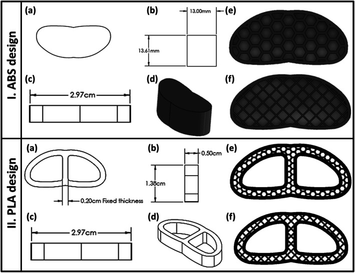
As indicated in Fig. 1a–d, the fused deposition modeling (FDM) 3D-printing technique was used to fabricate the vertebral and IVD scaffolds using ABS and PLA filaments, respectively. The scaffolds were classified according to the pore shape into cubic/grid (G) and hexagonal (H). Both shapes possess configurations with three infill densities; 25%, 50% and 75% as illustrated in Fig. 1e and f. The computer-aided design CAD model was sketched with Solidworks (2020–2021) and then transferred into an STL file.21 The samples were sliced and printed with the assistance of Ultimaker Cura (version; 4.6.1). The printing parameters were adjusted as explained in Table 1.
Fig. 1. Architecture of the 3D-printed vertebral corpus and cervical fusion cage (intervertebral disc, IVD): (a) apparent shape of the 3D-printed structure, (b–d) demonstration of the main dimensions of the design, and (e and f) Cura slicer images of the final porous construction of the 3D-scaffold with different pores patterns; honeycomb (H) or grid (G), before printing.
Parameters of 3D-printing of ABS vertebral scaffolds.
| Layer height (μm) | Infill speed (mm s−1) | Travel speed (mm s−1) | Extrusion temperature (°C) | Bed temperature (°C) | Nozzle diameter (mm) | Number of shells | |
|---|---|---|---|---|---|---|---|
| ABS | 100 | 50 | 100 | 245 | 90 °C | 0.4 | 2 |
| PLA | 100 | 50 | 100 | 215 | 60 °C | 0.4 | 2 |
2.2.2. Microscopic examination
Scanning electron microscopy, SEM (Nova Nano SEM, FEI, USA) was used to study the morphology and the porous pattern of both the 3D-printed ABS vertebral and the PLA IVD scaffolds as well as the gelatin-based hydrogel and MPS-NPs. Besides, all 3D-printed samples' morphologies were examined with the aid of an inverted and USB digital microscopy. In addition, transmission electron microscopy (TEM-JEOL, JEM-1230, Tokyo, Japan) at an accelerating voltage of 200 kV was utilized for the investigation of the morphology of the obtained MPS-NPs and mixed micelles.
2.2.3. Mechanical analysis
A universal testing machine (AGX-PLUS, Shimadzu, Japan) was used to investigate the compressive strength of cylindrical 3D-printed vertebral scaffolds with dimensions of 14 mm length × 25 mm diameter at 5 kN and at a rate of 1 mm min−1 and a maximum displacement of 2.4 mm (almost 10% of initial length). Young's modulus of all the 3D-printed ABS scaffolds was obtained from the slope of the straight part of the stress–strain curve from 0 to 10% strain.
2.2.4. Finite element analyses
Finite element analysis (FEA) calculations were used to predict the mechanical properties of the 3D-printed ABS scaffolds of different pores geometry; G and H. The factors affecting FEA calculations include material nature, porosity percentage and infill density. The type of material is controlled by its mechanical properties such as elastic modulus and Poisson ratio. Both items were measured for the used materials; ABS and PLA before the 3D-printing process, and used as inputs in the FEA. Three different infill densities (30%, 50% and 70%) were investigated for both shapes; G and H. Besides, the printed structures were tuned to be surrounded by two shells of 0.74 mm. FEA calculations involved the applying of many perpendicular loads on the upper surface of the chosen designs ranging from 1000 to 8000 N, see Tables S1 and S2† (in the ESI†). Biomechanical properties of the model were hypothetical to be isotropic, uniform, and elastic.17,22 Finally, extreme Von Mises stress values that the body could tolerate under the assumed load and stress were compared to experimental results of ultimate compressive strength from a universal test machine.17,22
2.3. Drug-loaded nanosystems
2.3.1. Mesoporous silica nanoparticles
Mesoporous silica nanoparticles (MPS-NPs) were prepared following our previous work.19 Briefly, TEOS was added in a dropwise manner to ethanolic mixture of ammonium hydroxide and CTAB. After that, the turbid solution was kept under stirring at 25 °C for 3 h. Then, it was washed several times by distilled water using vacuum pump. After complete drying of the obtained white powder at 25 °C, it was calcined using a muffle furnace (Magmatherm, Turkey) at 600 °C with a heating rate of 10 °C min−1 for 6 h. The prepared MPS-NPs were physically loaded with the antibiotic; either LEV or RIF by adding 1 g of the NPs into 100 ml of ethanolic solution of drug (5.7 mg ml−1) with a continuous stirring in the dark for 24 h. After that, both LEV-loaded and RIF-loaded MPS-NPs were centrifuged at 22 000 rpm for 20 min at 5 °C, and stored for further investigation.
2.3.2. Mixed nanomicelles
Mixed micelles nanosystem was prepared using two types of pluronics (F-127 and L-121) with different ratios as previously reported.20 In brief, the nanomicelles were loaded with anti-inflammatory drug (SIM) by dissolving the drug and the mixed pluronics with ratio (1 SIM : 10 pluronics) in acetone. Then, pluronic–SIM solution was added to deionized water, and lifted under stirring to get rid of the acetone and then centrifuged at 5 °C and 25 000 rpm for 15 min. The pellets of nanomicelles were frozen, lyophilized (FreeZone 6, Labconco lyophilizer) and stored for further use and characterization. The optimum ratio (5 F-127 : 5 L-121) was chosen depending on the calculations of drug entrapment efficiency (EE%), loading capacity (LC%) and drug releasing profiles as well as the measurements of both size and zeta potential. All physical, chemical and biological characterization of both types of the developed nanocarriers were carried out as illustrated in our previous articles.19,20
2.4. PRP collection
Acid citrate dextrose (ACD-A) buffer was prepared as an anticoagulant agent following the previously reported protocol.20 After that, blood sample was added to the prepared ACD-A buffer (with ratio 1 : 9 for ACD-A : blood). The blood components (plasma, buffy coat and erythrocytes) were separated using gradual centrifugations for 10 min at 4 °C. Then, the purified buffy coat was mixed with the lower one-third of the plasma volume to prepare the PRP. Polymerase chain reaction test (PCR) was used to compare the concentration of some blood components such as platelets and white blood cells (WBCs) counts as well as vascular endothelial growth factor (VEGF) and insulin-like growth factor 1 in both plasma and PRP.
2.5. Development of hydrogel
Different types of hydrogels were prepared by chemical crosslinking using different methods and crosslinkers to mimic the anatomical structure and the properties of the FSU due to the different nature and structure of either IVD or the vertebral body.
2.5.1. Gelatin-based semi-interpenetrating network hydrogel
This type of hydrogel was prepared by adding PEMULEN to the gelatin aqueous solution followed by crosslinking using tetrakis (THPC) at pH of 7.4. The ratio between gelatin, PMULEN and THPC was changed as reported in our previous work.19
2.5.2. Gelatin hydrogel
As in our previous work,20 gelatin discs were prepared by dissolving 10 g of gelatin in 100 ml distilled water at 37 °C. After that, the solution was immediately poured into a mold and was kept for gelation at 5 °C. Then, the gelatin discs were crosslinked by soaking them into 25% glutaraldehyde for different periods (1, 5, 15 min). The obtained hydrogels were purified several times using distilled water followed by soaking them in 50% w/v glycine for one hour to remove the glutaraldehyde residuals. Afterwards, they were washed via further soaking in distilled water for one hour and freeze-dried for further characterization. The optimum ratio of both gelatin hydrogel was nominated according to some physical characterizations such as elasticity as well as swellability and degradation degrees which were conducted as previously reported.19,20
2.6. In vitro studies
2.6.1. In vitro drug release study
As per our previous work,19,20 the release results for SIM-loaded mixed micelles and RIF/LEV-loaded MPS-NPs were obtained before and after their loading into the gelatin hydrogel and semi-interpenetrating hydrogel, respectively. Cumulative drug release was calculated using the following equation:
 |
1 |
where, Cn is the drug cumulative concentration of all samples, Cn mean is the drug concentration of each withdrawn sample, A is the aliquot volume, V is the receptor counterpart volume, n − 1 is the total number of all previous aliquots, and Cs mean is the sum of all withdrawn samples up to a certain time interval.
2.6.2. In vitro cytotoxicity assay
Cell viability % of the 3D-printed disc specimens either ABS or PLA scaffolds were detected via WST-1 assay using Abcam®kit (ab 1555902 WST-1 cell proliferation reagent). All samples were prepared to fit the area of wells in 24 well plates and were immersed with media for 1 h. Then, 40 μl of cell solution (6 × 10⁶ cells per ml) was added to the specimens' surface, and then they were incubated for 6 h. After that, an inverted microscope was used to test the cell adhesion before the cell dilution. Cells were incubated at 37 °C and 5% CO2 for 2 days after the addition of 360 μl of cell culture media. Post-incubation of the cells, as well as specimens and 10% (v/v) of dye were carried out at 37 °C for 1 h. At last, all media supernatants were transferred into another well plate for testing of the cell viability % at 450 nm using a BMG LABTECH FLUO star Omega microplate reader.23,24 Same procedure as in our published articles19,20 were followed to investigate the cell viability % for the developed nanocarriers and hydrogels.
2.6.3. Antimicrobial assay of RIF/LEV-loaded MPS-NPs
In vitro antimicrobial test on the free drugs (RIF and LEV), RIF-loaded MPS-NPs and LEV-loaded MPS-NPs were carried out to determine the MIC value of each specimen with TB infection at the Animal Health Research Institute (Bacteriology research department, Bovine tuberculosis Unit, Cairo, Egypt). All experiments and calculations were conducted according to the protocol reported by Thomas Schön et al.25 as well as all the conducted experimental steps was reported in details in our previous study.19 The proportion of resistant colonies was calculated by the following eqn (2):
 |
2 |
2.6.4. Lipoxygenase (LOX) inhibition assays
The lipoxygenase (LOX) inhibition assays of free SIM, unloaded and loaded mixed micelles were carried out as previously reported.20 Briefly, all samples were incubated with 100 μl of linoleic acid (substrate) to start the reaction. Afterwards, a mixture of 100 μl of soybean LOX solution (1000 U ml−1 in borate buffer solution, pH 9) and 200 μl of borate buffer were prepared with serial dilutions of the samples at 25 °C for 15 min. The inhibitory activity of each sample was detected by observing the absorbance's increase at 234 nm using a microplate reader (BIOTEK; USA). The inhibitory percentages were calculated according to the following equation:
| Inhibitory activity (%) = (1 − (As/Ac)) × 100 | 3 |
where, As is the sample absorbance and Ac is the control absorbance.
2.6.5. In vitro mineralization study of vertebral replacement using simulated body fluid (c-SBF)
The concentrated simulated body fluid (c-SBF) solution was prepared according to Kokubo and Takadama.26 The prepared vertebral scaffolds were immersed in 30 ml of c-SBF solution for two months at 37 °C in a shaking incubator (VWR International, CA, USA) at a speed of 120 rpm. The solution was replaced with a fresh c-SBF every week to simulate the natural environment of ECM inside the human body.27,28 Calcium ions concentration in the c-SBF fluid was determined weekly using atomic absorption spectrophotometry (AA-7000/GFA-7000/ASC-7000, Shimadzu, Japan), while the phosphate ions concentration was determined using UV-visible spectrophotometry (Evolution UV 600, Thermo Scientific, USA) at the wavelength of 700 nm.19
2.7. In vivo biocompatibility study
2.7.1. Subcutaneous implantation
The surgical procedure was carried out according to the guidelines after approval of “The Institutional Animal Care and Use Committee (ARC-IACUC)”, Agricultural Research Center, Cairo, Egypt (number; ARCAH2206 and ARCAH2207). Twenty-four Wistar rats (200–250 g) were divided into six groups (four rats/group) as described in Table 2; control, scaffold filled with drug-free hydrogel (implant I) and scaffold filled with drug-loaded hydrogel (implant II). In the case of 3D-printed vertebral scaffold (ABS-based), two implants have been included; drug-free implant (G2) and RIF/LEV-loaded implant (G3). While, in the case of 3D-printed IVD scaffold (PLA-based), the scaffolds were classified into drug-free implant (G4), SIM-loaded implant (G5), SIM and PRP-loaded implant (G6).
The composition and the denoted code of the implants that were applied at different animal groups.
| Code | Implant/scaffold |
|---|---|
| G1 | Control |
| G2 | 3D-printed ABS-plain |
| G3 | 3D-printed ABS-loaded RIF and LEV |
| G4 | 3D-printed PLA-plain |
| G5 | 3D-printed PLA-loaded SIM |
| G6 | 3D-printed PLA-loaded SIM and PRP |
Anesthesia was induced by an intraperitoneal injection of 0.5 ml of ketamine. Five mm incisions were created on the posterior dorsomedial skin of the animals, and lateral subcutaneous pockets were developed by blunt dissection. Scaffolds (8 mm length × 2 mm width × 0.5 mm thickness) were weighted (W0) and then implanted into the subcutaneous pockets, followed by suturing using Vicryl 5.0 sutures. Afterward, all animals, after recovery from anesthesia, were kept under observation to make sure they are performing well. Features of the tissue injury and the existence of edema were detected before eliminating the implants. The rats were anesthetized by carbon dioxide euthanasia and were sacrificed following the ethical steps via cervical dislocation. After 28 days, implanted samples were retrieved with their surrounding tissues and were fixed in 10% paraformaldehyde overnight. Samples of each group were divided for biodegradation studies and histological examination.29,30 Samples for the biodegradation test were washed carefully (n = 3) to eliminate the residual tissue by PBS buffer. The scaffolds were lyophilized to quantify their weight loss and were stored at 4 °C for further examinations.
2.7.2. Histological and immunohistochemistry
Samples were cleaned with Dulbecco's-Phosphate Buffered Saline (DPBS) followed by their incubation in 30% sucrose solution overnight in the refrigerator, then they were embedded in Optimal Cutting Temperature (OCT) compound followed by their flashing and freezing using liquid nitrogen. Afterwards, specimens were fixed in paraffin and were cryosectioned (10 μm). The slides were stained with hematoxylin and eosin (H&E). For immunohistological analysis, the samples with the surrounding tissue were fixed in 4% (v/v) paraformaldehyde overnight, and the immunohistochemistry staining for collagen, CD68, and CD8 was performed on the cryosections.29,30
2.7.3. Anti-inflammatory markers
Blood withdrawals were carried out before and after the predetermined period (28 days) for measuring C-reactive protein (CRP), fibrinogen and the complete blood count (CBC). In addition, IL 6 levels were measured in the removed tissues via polymerase chain reaction (PCR).19,20
2.8. Statistical analysis
All data were expressed as a mean ± standard deviation. Significance was tested using one-way and T-test ANOVA of variance (ANOVA) to all data using GraphPad Prism Software version 6 (*p < 0.05, **p < 0.01, ***p < 0.001, and ****p < 0.0001).
3. Results and discussion
In the current study, FSU (vertebral and IVD) was designed to mimic the function and anatomical structure of the vertebral body and IVD as well as their ECM, respectively. This concept was proven by measuring the physicochemical, mechanical and biological (in vitro and in vivo) properties of each constitute of both replacements. Vertebral replacements are composed of the 3D-printed ABS scaffold filled with the gelatin-based semi-IPN hydrogel laden with drugs-loaded MPS-NPs. While the IVD replacement is composed of 3D-printed PLA scaffolds incorporating a gelatin-based hydrogel containing SIM-loaded mixed pluronic nanomicelles and PRP. The optimum properties for each individual part were assessed as will be explained in the following sections.
3.1. 3D-printed FSU
3.1.1. Microscopic examination
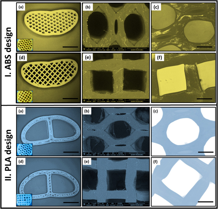
The morphology and pore structure of different patterns of the 3D-printed ABS and PLA scaffolds were examined by SEM, inverted and USB digital microscopes (Fig. 2I and II). The parameters like the percentage and size of pores were altered with various infill densities during the 3D-printing process as well as the material type. It was found that, as the infill density increases, the dimensions of the pattern decrease with increasing the number of pores. As noted from the optical microscopy images (Fig. 2a–d), the attempted models of fabricated scaffolds mimic the design of the commercial cage replacements. All micrographs showed that the targeted pore designs (H or G) in the solid-works files were successfully achieved after the 3D-printing process. Both patterns (H and G) were ascertained by inverted microscopy (Fig. 2c and f) and SEM microscopy.
Fig. 2. Imaging of the fabricated 3D-printed ABS and PLA designs (50% infill) with honeycomb and grid patterns using different types of microscopes; (a and d) optical microscope, (b and e) scanning electron microscope (SEM), and (c and f) USB digital microscopy.
Moreover, the SEM micrographs (Fig. 2b and e) were used to calculate the pore size of each pattern. Measurement of all dimensions was performed with the aid of ImageJ software (ij153-win-java8). For 50% infill ABS, the complete area of the H pattern was 1.34 ± 0.04 mm2 which was found to be smaller than that of G pattern (1.64 mm2). While, in the case of PLA scaffold, the entire area of each pattern in (H) is 1.5 mm2 and was reduced to 1.44 mm2 in the case of G. Therefore, by maintaining the material and the infill density constant, the change in pore shape (H or G) affects both the pore dimension and area and consequently the number of pores. For instance, in the same scaffold area, the number of pores obtained in the case of the H pattern was larger than in the G pattern.
3.1.2. Mechanical analysis
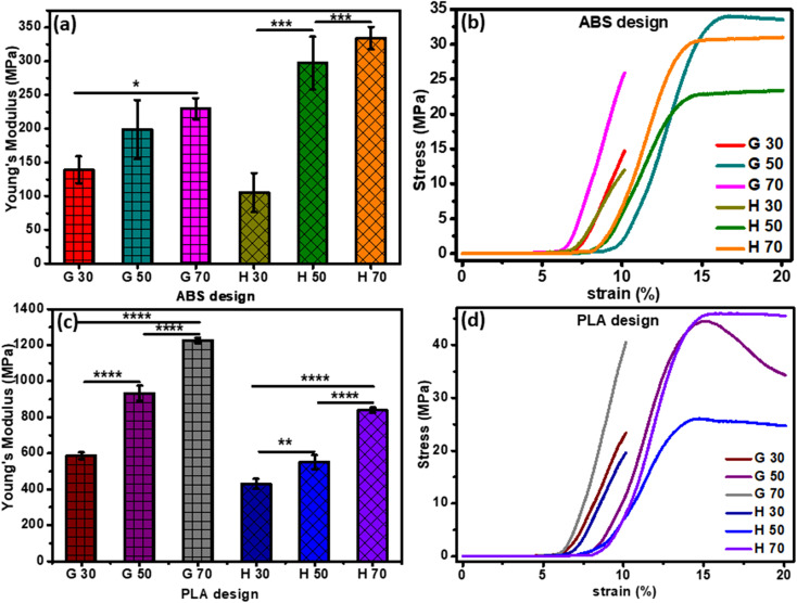
Stress–strain curve and Young's modulus values of the 3D-printed ABS scaffolds are demonstrated in Fig. 3a and b. Samples with G pattern possessed ultimate tensile strength values of 14.67 MPa, 33.59 MPa and 25.97 MPa as well as strain % values of 10.14%, 16.88% and 10.14% for the 30%, 50% and 70% infill, respectively. In the case of the H pattern, the ultimate tensile strength values were found to be 11.96 MPa, 22.78 MPa and 30.57 MPa with strain % values of 10.14%, 14.88% and 14.71%, for the 30%, 50% and 70% infill, respectively.
Fig. 3. Mechanical characterization: (a and c) Young's modulus of H and G patterns of vertebral and IVD scaffolds, respectively, and (b and d) stress–strain curves of H and G patterns of vertebral and IVD scaffolds, respectively. The p-values (2-way ANOVA) represent correlation coefficients between all printed samples (*significant at p < 0.05; **significant at p = 0.005; ****significant at p < 0.0001).
The structure and density of pores of the 3D-printed scaffolds found to have an impact on the attained mechanical properties, particularly the elastic modulus. For instance, decreasing the pore density (i.e., larger pore size) declined Young's modulus. Furthermore, Young's modulus values were found to be dependent on the infill density. For example, Young's modulus of the 30%-infill G and H pattern were 139.10 ± 19.91 N mm−2 and 105.33 ± 29.14 N mm−2, respectively. These values upsurged to 229.51 ± 15.52 N mm−2 and 334.32 ± 16.42 N mm−2, respectively upon increasing the infill density to 70%.
Fig. 3c and d demonstrate Young's modulus that was calculated using the stress–strain curve of all PLA 3D-printed samples. All samples with G patterns depicted ultimate tensile strength of 40.55 and 24 MPa for 70% and 30% infill, respectively. In the case of the H patterns, the 70% and 30% infill have attained ultimate tensile strength values of 45.72 and 19.67 MPa, respectively. The elasticity of specimens was influenced by the printing parameters such as the shape of the patterns (H or G) and the infill density. For example, an increase of porosity % with a smaller pore size led to higher values of Young's modulus. Moreover, the value of elastic modulus of the highest infill percentage of both H and G patterns was 1227.298 ± 14.95 N mm−2 and 839.0966 ± 14.09 N mm−2, respectively. While, for the 30% infill, the elastic modulus attained 586.5607 ± 18.91 N mm−2 and 430.2339 ± 27.66 N mm−2 for G and H, respectively.31,32 Elena Provaggi et al. reported that increasing infill density resulted in a higher value of both Young's modulus and compressive strength. Additionally, both properties were greater in the case of the H pattern than the G pattern.17 The same finding was founded by Uday Kiran Roopavath et al., and they reported that the porosity of their scaffold has a significant role in controlling mechanical properties like compressive modulus and strength. They showed that the compressive modulus of 50% and 100% infill was 43 ± 10.78 MPa and 275 ± 6.27 MPa, respectively.31 The Young's modulus values attained in the current study confirm that our scaffolds are more elastic than the Roopavath design at the same infill density of 50%.
3.1.3. Finite element analyses
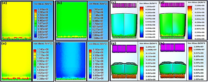
Biomechanical properties of orthopedic scaffolds with specific geometry can be predicted via the finite element analysis (FEA) calculations.33–35 Many studies were carried out by Zheng-Cheng et al.36 to detect a suitable cage model for targeting the region of the lumbar spine by analyzing the stress distribution by FEA data. Recently, cages have been used for the treatment of backbone degenerative problems. However, the geometry of the cage and its effect on its biomechanics were not investigated. Zheng-Cheng et al. have used FEA to reach the proper cage design for the lumbar region of spin through the interpretation of the FEA results of the stress distribution.36 In the current study, both H and G patterns with 70% infill were nominated to compare their biomechanical properties as well as to estimate the effect of different pore patterns on the Von Mises stresses (σGY) results after applying a vertical force in the range of 1000–8000 N as in Fig. 4.
Fig. 4. Finite element analysis (FEA) that shows Von Mises stress of 70% infill; (a–d) for the ABS scaffold where (a and c) for H pattern, and (b and d) for G pattern as well as PLA scaffolds (e–h) where (e and g) for H pattern, and (f and h) for the G pattern.
Using the universal testing machine, the ABS 70% infill H-pattern scaffold showed a maximum yield strength of 31.04 MPa after the experimental application of 4726.12 N, while the G-pattern one with the same infill % demonstrated 24.75 MPa of yield strength after the experimental application of 6115.01 N. While, their Von Mises stresses (σGY), after applying 4000 N using solid work calculations, were found to be 40.86 and 30.16 MPa, respectively. Applying load values of more than 3000 N might lead to scaffold failure and be considered an unsafe force. This was anticipated because the FEA at 4000 N showed Von Mises stress (σGY) value more than the ultimate strength from experimental testing. The results indicated that the safe maximum load as obtained from both the FEA and experimental measurements for H and G patterns was 3000 N (Fig. 4a and 3d). Upon comparing the obtained mechanical results with that reported by Elena Provaggi et al.17 who investigated the effect of a vertical load of 1000 N on an ABS spinal cage with a design similar to that reported in this work but with bigger dimensions, our proposed scaffold depicted enhanced mechanical properties. In another study, Serra et al. tested the elasticity of a 3D-printed polycarbonate scaffold via applying 2500 N.22 The current study have showed similar elasticity results of their scaffold but with applying a higher force (4000–6000 N), which confirms a high elasticity of our developed scaffolds as compared to theirs. Besides, according to the reported values by Serra et al.22 and Derek H. Rosenzweig et al.,37 the normal trabecular bone has a modulus value ranging from 50–500 MPa, so the mechanical properties of our developed scaffolds are in a similar range of the compact normal bone. It is also worth to mention that Derek H. Rosenzweig et al.37 reported a high mechanical stability of the ABS scaffolds for orthopedics applications such as cartilage and intervertebral disc (IVD) tissue regeneration. These obtained results confirmed the integration of our design with the human bones without facing the problem of stress shielding.
The maximum yield strength was attained for the PLA 70% infill (H) sample (46.19 MPa) under a maximum force of 6961.34 N (Fig. 3b), while the extreme value of its Von Mises stresses (σGY) under assumed forces of 6000 and 7000 N were 66.22 and 77.26 MPa, respectively. These values are considered unsafe because they will result in an implant fracture. Accordingly, the appropriate maximum load that the sample could endure without failure, based on FEA, is 4000 N with a Von Mises value of 44.15 MPa. For the same infill of 70%, changing the pattern from H to G led to reducing the proper maximum load to 3000 N ≤ F ≤ 4000 N. Elena Provaggi et al. have applied an axial force around 1000 N to a similar PLA-based design with different dimension. Comparing the outcomes of the current study with their results showed that the biomechanical properties of our newly-tailored scaffolds were improved (Fig. 3e–h).17,22 Both Elena Provaggi et al.17 and Serra et al.22 used the FEA to evaluate the biomechanics of their reported scaffolds that are of analogous design to ours by applying 1000 N, and their FEA results were almost equal to our Von Mises stresses (σGY) results; 10.22 and 7.54 MPa for H and G, respectively.
3.2. Drug-loaded nanosystems
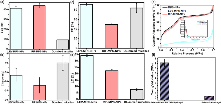
The optimum ratio of mixed nanomicells was found to be that of equal amounts of pluronics; F-127 and L-121. As shown in Fig. 5a–d, the developed nanomicelles attained a particle size and zeta potential of 83.95 ± 0.52 nm and −9.96 ± 7.10 mv, respectively. In addition, the measured EE% and LC% showed values around 84% and 7.5%, respectively. All miscellaneous ratios showed the same range of both values, so this optimum ratio was selected based on the obtained release profiles of the drugs. The optimum ration showed the slowest release profile, where it depicted a burst release of SIM within the first day of the release period followed by a sustained release of 88.4% of SIM after 21 days. Besides, as per our previous studies, the FTIR spectra and DSC thermogram of this optimum nanoformulation proves the successful incorporation of SIM into the mixed nanomicelles.19,20
Fig. 5. Physical and mechanical properties of the developed optimum nanoforms and hydrogel constituents of the vertebral and IVD scaffolds, (a) particle size, (b) surface charge, (c) entrapment efficiency %, and (d) loading capacity % of LEV/RIF-loaded MPS-NPs and SIM-loaded mixed nanomicelles, and (e) nitrogen adsorption–desorption isotherm graph of LEV/RIF-loaded MPS-NPs, and (f) the mechanical elasticity of the developed gelatin hydrogels.
The prepared plain, and LEV- and RIF-loaded MPS-NPs showed identical particle size ranged from 400 to 450 nm and possess a negative surface charge, Fig. 5a–d. LC% of LEV was greater than that of RIF into the MPS-NPs and this finding was ascertain by Barrett–Joyner–Halenda (BJH) and Brunauer–Emmett–Teller (BET) analyses as illustrated in Fig. 5e. Besides, as per our earlier investigation,19,20 the TGA thermogram proves the higher thermal stability of the prepared plain MPS-NPs that improves the lower thermal stability of both loaded antibiotics (LEV and RIF). Both XRD diffractogram and the FTIR spectrum depicted that all the dominant peaks of the antibiotics (LEV and RIF) were disappeared after their loading into the MPS-NPs which confirms their successful physical post-loading into the nanocarrier.19,20
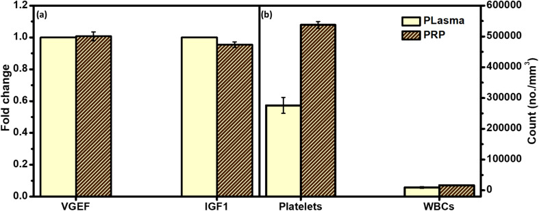
Fig. 6 gives a comparative overview of the developed PRP components and their peers in either plasma or the whole blood. As can be noted from the figure, there is no significant fold change of both growth factors between the collected PRP and plasma. In addition, the count of platelets was higher in the case of PRP as compared to the whole blood.
Fig. 6. Polymerase chain reaction (PCR) assay to investigate the difference between physiological composition of the isolated platelets rich plasma (PRP) and (a) blood plasma through measuring the count of their growth factors; vascular endothelial growth factor (VGEF) and insulin-like growth factor 1 (IGF1), and (b) whole blood through measuring the count of their platelets and WBCs. p-values (t-test) represents the correlation coefficients between all PRP samples and plasma (*significant at p < 0.05; ns significant at p = 0.5632–0.9167).
3.3. Bioactivity test
Increasing of both calcium and phosphate ions deposited on the sample surfaces ascertain the bioactivity of the developed vertebral replacement.19 This was attributed to the ability of the replacement to form bonds with calcium and phosphate and to allow their growth with time to generate an appetite layer.
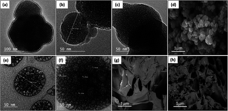
Fig. 7a–c, e and f demonstrate the TEM micrographs of plain MPS-NPs, LEV-loaded MPS-NPs, and the RIF-loaded MPS-NPs as well as unloaded and SIM-loaded mixed nanomicelles, respectively. As apparent from the figure, all the micrographs depicted a porous hexagonal structure with rounded edges that seems like the spherical shape. From Fig. 7a–c, these particles possess average diameter around 141.29 ± 14.96 nm for plain MPS-NPs beside 150.15 ± 19.59 for LEV-loaded MPS-NPs and 158.41 ± 43.90 nm for RIF-loaded MPS-NPs. As appeared from Fig. 7e and f, the TEM micrographs depicted clusters of spherical shapes of both plain and SIM-loaded mixed nanomicelles, but the cluster size of plain mixed nanomicelles are smaller than SIM-loaded mixed nanomicelles. The SEM micrograph of the synthesized MPS-NPs (Fig. 7d) confirmed their spherical nature, and the SEM micrographs of the prepared semi-interpenetrating network gelatin hydrogel showed a compact lamellar structure with irregular porous shape, Fig. 7g. SEM micrographs of the prepared gelatin hydrogel using GA revealed an interconnected porous structure with irregular shapes (diameter of 30–750 μm; ImageJ software), Fig. 7h.
Fig. 7. TEM micrographs of (a) plain MPS-NPs, (b) LEV-loaded MPS-NPs, and (c) RIF-loaded MPS-NPs as well as (e) unloaded mixed nanomicelles and (f) SIM-loaded mixed nanomicelles. SEM micrographs of the synthesized (d) MPS-NPs, (g) semi-IPN gelatin hydrogel and (h) gelatin–GA hydrogel.
3.4. Development of hydrogels
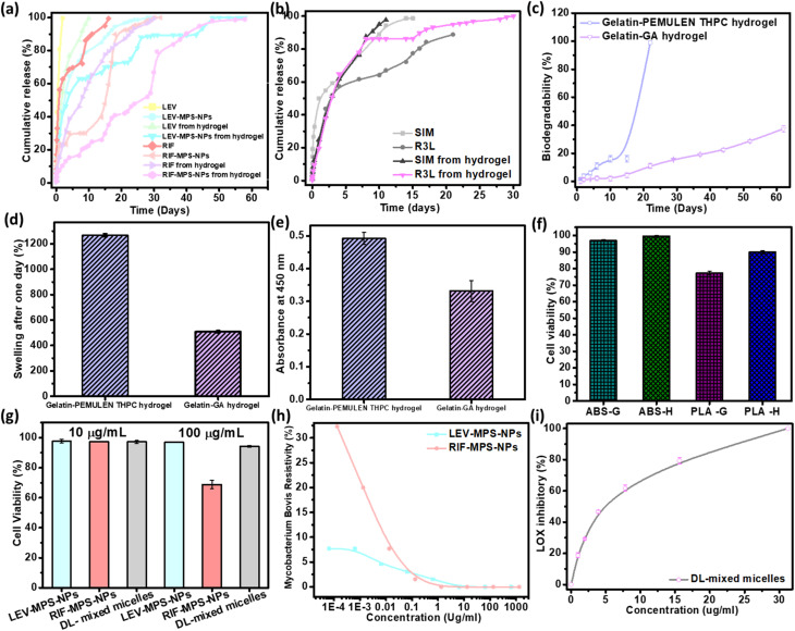
As can be noted from Fig. 8a, there is a sequential release of the antibiotics (LEV and RIF) from the hydrogel after 15 days. The release profile of LEV from the LEV-loaded MPS-NPs was faster than RIF-loaded MPS-NPs after 30 days. As can be noted from the figure, loading of the drugs-loaded MPS-NPs into the hydrogel matrix prolonged the drug(s) release up to 60 days.
Fig. 8. In vitro studies of the developed FSU constitutes. Release study of (a) the antibiotics (LEV and RIF) from LEV/RIF-loaded MPS-NPs and (b) the SIM from SIM-loaded NPs as well as their release from the optimum gelatin hydrogel matrix, (c) biodegradation % after two months and (d) swelling % after the first day of the developed gelatin hydrogels. Cell viability % of (e) gelatin hydrogel, (f) 3D-printed samples, and (g) plain nanocarriers, (h) MIC value of both LEV- and RIF-loaded MPS-NPs against TB pathogen, (i) anti-inflammatory test of SIM-loaded mixed nanomicelles by testing their inhibition effect on lipoxygenases (LOX) enzyme activity.
As can be observed from the release study in Fig. 8b, SIM-loaded NPs showed a gradual release profile from the hydrogel where about 86.16% of SIM was released after 9 days, while the rest amount was sustained released after 21 days. Therefore, the hydrogel may confer a good environment for regulation of SIM release. As investigated before,20 the characteristic peaks of gelatin in the developed gelatin-based hydrogel decreased upon increasing the soaking time in the glutaraldehyde which consider an evidence of increasing the crosslinking degree. Besides, all the developed gelatin-based hydrogel samples degraded slowly over the first 15 days followed by a quick degradation, Fig. 8c. The hydrogel degradation was found to be crosslinking-dependent, where increasing the soaking time of gelatin in glutaraldehyde decreases the degradation rate. Based on the swelling calculations (Fig. 8d), all gelatin hydrogel samples possessed the same equilibrium point after the first day, which confirms the limited effect of crosslinking degree on the swelling value. In addition, increasing the crosslinking extent improved the elasticity of the prepared hydrogel. Young's modulus of value 0.72 ± 0.0079 MPa was attained by the optimum gelatin hydrogel sample (15 min soaking).20 Therefore, this sample was compatible with the non-homogenous mechanical properties of the normal IVD.
As per the FTIR spectra of the prepared semi-IPN hydrogel reported in our earlier study,19 a reduction in the characteristic peaks of gelatin was noted upon crosslinking with THPC, and most of PEMULEM characteristic peaks disappeared confirming its well-dispersion in the semi-IPN hydrogel. Optimum ratio of hydrogel was assigned to the higher concentration of gelatin (12%) and the lower amount of THPC due to its higher elasticity, lower degradation rate (Fig. 8c) and the higher swelling % (Fig. 8d). The semi-IPN hydrogel attained a Young's modulus value around 7.18 ± 0.78 MPa, and a swelling of 508.9 ± 7.9% to 543.1 ± 5.9% after 24 hours. In addition, the degradation pattern depicted a steady state up to 15 days followed by a fast degradation rate up to 22 days.
3.5. In vitro cytotoxicity assay
Cell adherence and subsequent proliferation were influenced by the soaking time in glutaraldehyde, whereas higher soaking time reduced the cell viability % as compared to the lower soaking time (Fig. 8e). The cell viability test in the case of the semi-IPN gelatin hydrogel confirmed its biocompatibility with normal cells, but a lower cell viability % was observed at the higher crosslinking degree.
Fig. 8f shows the HFS cell viability % of the 3D-printed scaffolds (50% infill; H and G) through testing the absorbance of WST-1 dye. As can be noted from the graph, the viability % of ABS with H pattern (99.50 ± 0.56%) slightly exceeds that of the G pattern (96.89 ± 0.55%). The viability % of PLA scaffold with H pattern is relatively higher than that of the G pattern with values of 89.91 ± 0.96% and 77.22 ± 1.19%, respectively. The obtained results confirm the principle behind different implant designs and how it influences its mechanical and biological interaction with the human body.38,39 These results confirmed that HFS cells could proliferate on both 3D-printed patterns (H and G). Besides, our obtained cell viability results were very similar to that reported by Derek H. Rosenzweig et al.37 and consequently, our newly-developed 3D-printed ABS vertebral scaffolds were found to be nontoxic as well as have depicted a good ability to enhance the regeneration of new tissue through improving the differentiation of normal cells. Theodoridis et al. fabricated a polycaprolactone 3D-printed scaffold with three different designs (MESO, RO45, and 3DHC) of deposited layers and studied the viability on adipose-tissue–derived mesenchymal stem cells (ADMCs) at different stages (null, MSCs, and differentiated). They confirmed that the different designs depicted various viability, chondrogenic differentiation as well as mechanical and cell proliferation.38 In addition, the biocompatibility of the metabolic by-products has been proven in several research studies.40
As shown from Fig. 8g, the cell viability % at both concentrations of 10 and 100 μg ml−1 was around 94.23 ± 0.64%. The optimum ratio of the prepared mixed nanomicelles showed a highest cell proliferation with IC50 value of about 4.17 μg ml−1 that is greater than that of the free SIM (0.5 μg ml−1).20 Both LEV- and RIF-loaded MPS-NPs showed a nearly equal viability % at 10 μg ml−1, while with increasing the concentration into 100 μg ml−1, the measured viability % of LEV-loaded MPS-NPs (96.87 ± 0.18%) was higher than that of RIF-loaded MPS-NPs (68.76 ± 2.75%).
Fig. 8h investigated the MIC values for LEV-loaded MPS-NPs and RIF-loaded MPS-NPs against mycobacterium B. Minimum inhibitory concentrations (MIC) value for LEV-loaded and RIF-loaded MPS-NPs against Mycobacterium B. were 6.50 and 1.33 μm ml−1, respectively. Additionally, Fig. 8i demonstrated the anti-inflammatory effect of SIM on lipoxygenases (LOX) enzyme activity. The value was improved upon their incorporation into the nanomicelles where their IC50 was 4.6 ± 1.1 μg ml−1 as compared to the free SIM of 9.7 ± 0.9 μg ml−1.20
3.6. In vivo biocompatibility study
3.6.1. Subcutaneous implantation
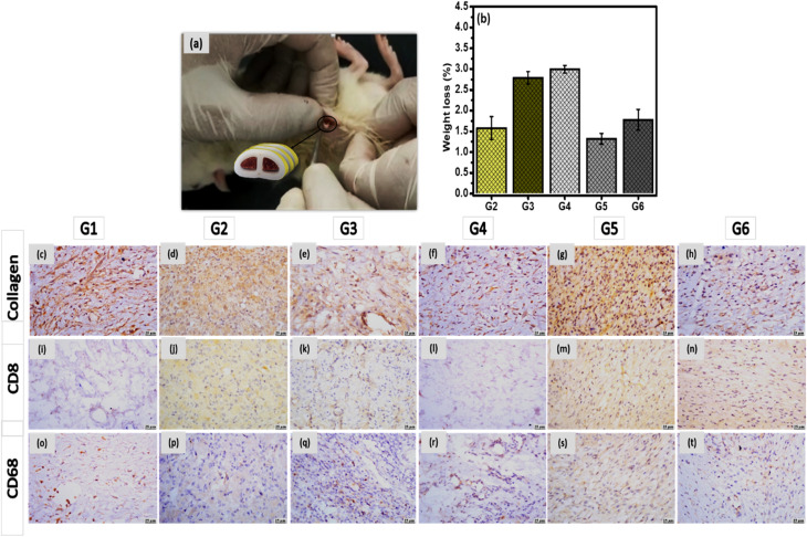
A biocompatibility test of the developed vertebral and IVD implants were carried out by monitoring their side effects on the biological system. In the case of ABS replacement, all animals were not be administrated by antibiotics to avoid their interference with RIF or LEV. Blood samples were withdrawn from the rats pre- and post-conduction of the biocompatibility test to investigate the effect of the FSU implant on the CBC as well as CRP and fibrinogen levels as anti-inflammatory markers. There were no significant effect on these parameters values before and after the experiments. In addition, all samples were not affected by the physiological harsh conditions, where their weight loss was non-significant and they keep their height after implantation, Fig. 9b.
Fig. 9. (a) A schematic illustration of subcutaneous surgical process, (b) weight loss % of the developed unloaded replacement G2 and G4, and the loaded replacement G2, G5 and G6 implants before and after animal sacrifice, and the photomicrographs of skin using collagen, CD8 and CD68 stain; control group G1 (c, i and o), unloaded 3D-printed ABS scaffold (d, j and p), 3D-printed ABS scaffold loaded RIF & LEV (e, k and q), unloaded 3D-printed PLA scaffold (f, l and r), 3D-printed PLA scaffold loaded-SIM (g, m and s), and the 3D-printed PLA scaffold loaded-SIM & PRP (h, n and t), respectively.
Subcutaneous implantation of both vertebral and IVD scaffolds (incorporating gelatin hydrogel laden with drug-loaded nanocarriers) were performed for 28 days, as per our previous study,19,20 to test their in vivo biocompatibility. Histological and histochemical micrographs demonstrated normal healing signs including macrophages, T-cells, angiogenesis and granulation reactions. Introducing PRP and SIM in the case of IVD scaffold enhanced the healing process and reduced the inflammation reactions. Same findings were observed in the case of vertebral scaffolds that showed a progress in the healing process and reduction in the appearance of any pathogen. In the current study, both scaffolds were tested after their incorporation into the 3D-printed samples to investigate their biocompatibility with the biological system.
Microscopic examinations of collagen, CD8 and CD68 expression were investigated in different groups. Strong expression of collagen was detected in G5 and G6, meanwhile, moderate expressions were observed in G2 and G3. Higher expression was observed in G1, and G4 (Fig. 9c–h). In the case of CD8, groups G2, G3, G5 and G6 have showed mild expression, however weak to negative expression was determined in G1and G4 (Fig. 9i–n). In addition, moderate expression of CD68 was detected in G5 and G6, while mild expression was detected in G2 and G3. Weak to limited expressions of CD68 were noticed in G1 and G4 (Fig. 9o–t). All histological observations ascertain the safety of each component of FSU replacement on the living tissue. Besides, FSU replacement could replace the damaged vertebrae and IVD due to the TB infection with higher potential to regenerate these tissue as well as acting against the TB pathogen.
The limitations of the current study involves the addition of pourous pockets in the upper and lower surfaces during printing of the middle 3D-printed scaffold of the unit to hold tightly the other scaffold from its both sides. Besides, the small sample size is another limitation. However, these two limitations wouldn't have a potential impact on the study's findings and conclusions, and may be considered in the future study during the designing of the proposed unit to mimics the real FSU.
4. Conclusion
Kyphosis of the backbone results from damaging of FSU (vertebrae and IVD) structure, and caused by infection with TB bacteria. As a result, there is a critical need to combine both vertebral and IVD replacements together in on unit. This unit is not only to fix the damaged parts but also to treat the spinal TB. In the current study, the FSU replacement was developed using three strategies; 3D-printing technique, macromolecular chemistry and nanotechnology. The obtained mechanical results, the combination in our study between the 3D-printed IVD scaffold and the gelatin-based hydrogels incorporating different drug-loaded NPs with different mechanical properties and water content will be appropriate to the diversity of non-homogenous stress on different parts of FSU. In vitro and in vivo studies affirmed the biocompatibility of the developed FSU replacement to the biological cells. Accordingly, our fabricated 3D-printed FSU replacement is auspicious to replace the damaged FSU along with a great potential to get rid of spinal TB. Besides, and given the promising study findings, the utilization of the developed drug-eluting scaffold system can be extrapolated to treat not only spinal TB but also to resolve diverse backbone/spine problems that need a critical surgical process including degenerative IVD and its consequences like atherosclerosis, sliding or spondylolisthesis and severe traumatic bone fracture.
Data availability
The raw data of the current study will be available upon request.
Conflicts of interest
The authors have no relevant affiliations or financial involvement with any organization or entity with a financial interest in or financial conflict with the subject matter or materials discussed in the manuscript. This includes employment, consultancies, honoraria, stock ownership or options, expert testimony, grants or patents received or pending, or royalties.
Supplementary Material
Acknowledgments
The authors extend their appreciation to the Deanship of Scientific Research at Imam Mohammad Ibn Saud Islamic University (IMSIU) for funding and supporting this work through Research Partnership Program no. RP-21-09-68.
Electronic supplementary information (ESI) available. See DOI: https://doi.org/10.1039/d3ra02351f
References
- Zumwalt M. Reddy A. P. Biochim. Biophys. Acta, Mol. Basis Dis. 2020;1866:165624. doi: 10.1016/j.bbadis.2019.165624. [DOI] [PubMed] [Google Scholar]
- Metropolitan T. Hospital G. Japan Med Assoc J. 2004;47:227–233. [Google Scholar]
- Rasouli M. R. Mirkoohi M. Vaccaro A. R. Yarandi K. K. Rahimi-Movaghar V. Asian Spine J. 2012;6:294. doi: 10.4184/asj.2012.6.4.294. [DOI] [PMC free article] [PubMed] [Google Scholar]
- Aboutaleb E. Noori M. Dinarvand R. Int. Nano Lett. 2012;2:1–8. doi: 10.1186/2228-5326-2-1. [DOI] [Google Scholar]
- Rajasekaran S. Khandelwal G. Eur. Spine J. 2013;22:587–593. doi: 10.1007/s00586-012-2337-5. [DOI] [PMC free article] [PubMed] [Google Scholar]
- Friis E. A., Arnold P. M. and Goel V. K., in Mechanical Testing of Orthopaedic Implants, Elsevier, 2017, pp. 161–180 [Google Scholar]
- Li L. Yu F. Jiang Q. J. Orthop. Translat. 2019;17:26–41. doi: 10.1016/j.jot.2018.09.003. [DOI] [PMC free article] [PubMed] [Google Scholar]
- Bai X. Gao M. Syed S. Zhuang J. Xu X. Zhang X. Q. Bioact. Mater. 2018;3:401–417. doi: 10.1016/j.bioactmat.2018.05.006. [DOI] [PMC free article] [PubMed] [Google Scholar]
- Hernández-González A. C. Téllez-Jurado L. Rodríguez-Lorenzo L. M. Carbohydr. Polym. 2020;229:115514. doi: 10.1016/j.carbpol.2019.115514. [DOI] [PubMed] [Google Scholar]
- Tsou Y. Khoneisser J. Huang P. Xu X. Bioact. Mater. 2016;1:39–55. doi: 10.1016/j.bioactmat.2016.05.001. [DOI] [PMC free article] [PubMed] [Google Scholar]
- Farazin A. Zhang C. Gheisizadeh A. Shahbazi A. Biomed. Eng. Adv. 2023;5:100075. doi: 10.1016/j.bea.2023.100075. [DOI] [Google Scholar]
- Corona P. S. Vicente M. Tetsworth K. Glatt V. Injury. 2018;49:S51–S59. doi: 10.1016/j.injury.2018.07.017. [DOI] [PubMed] [Google Scholar]
- Mishra A. Verma T. Vaish A. Vaish R. Vaishya R. Maini L. Chin. J. Traumatol. 2019;22:350–355. doi: 10.1016/j.cjtee.2019.07.006. [DOI] [PMC free article] [PubMed] [Google Scholar]
- Zhang W. Sun C. Zhu J. Zhang W. Leng H. Song C. Biomater. Sci. 2020;8:4147–4156. doi: 10.1039/D0BM00361A. [DOI] [PubMed] [Google Scholar]
- Farazin A. Mohammadimehr M. Naeimi H. Int. J. Biol. Macromol. 2023;241:124572. doi: 10.1016/j.ijbiomac.2023.124572. [DOI] [PubMed] [Google Scholar]
- Zhang B. Pei X. Zhang X. Composites, Part B. 2018;155:112–121. doi: 10.1016/j.compositesb.2018.08.047. [DOI] [Google Scholar]
- Provaggi E. Capelli C. Rahmani B. Burriesci G. Kalaskar D. M. Mater. Des. 2019;163:107540. doi: 10.1016/j.matdes.2018.107540. [DOI] [Google Scholar]
- van Dijk M. Smit T. H. Burger E. H. Wuisman P. I. Spine. 2002;27:2706–2714. doi: 10.1097/00007632-200212010-00010. [DOI] [PubMed] [Google Scholar]
- Yahia S. Khalil I. A. El-Sherbiny I. M. Int. J. Pharm. 2023;633:122609. doi: 10.1016/j.ijpharm.2023.122609. [DOI] [PubMed] [Google Scholar]
- Yahia S. Khalil I. A. El-Sherbiny I. M. Int. J. Biol. Macromol. 2023;225:730–744. doi: 10.1016/j.ijbiomac.2022.11.136. [DOI] [PubMed] [Google Scholar]
- Kazeroni Z. S. Telloo M. Farazin A. Saber-Samandari S. Sheikhbahaei E. Kamyab-Moghadas B. Joneidi Yekta H. Esmaeili S. Khandan A. Aust. J. Mech. Eng. 2021;5:109–120. [Google Scholar]
- Serra T. Capelli C. Toumpaniari R. Orriss I. R. Leong J. J. H. Dalgarno K. Kalaskar D. M. Biofabrication. 2016;8(3):035001. doi: 10.1088/1758-5090/8/3/035001. [DOI] [PubMed] [Google Scholar]
- Khalil I. A. Saleh B. Ibrahim D. M. Jumelle C. Yung A. Dana R. Annabi N. Biomater. Sci. 2020;8:5196–5209. doi: 10.1039/D0BM00935K. [DOI] [PMC free article] [PubMed] [Google Scholar]
- Michelini L. Probo L. Farè S. Contessi Negrini N. Mater. Lett. 2020;272:127865. doi: 10.1016/j.matlet.2020.127865. [DOI] [Google Scholar]
- Schön T. Werngren J. Machado D. Borroni E. Wijkander M. Lina G. Mouton J. Matuschek E. Kahlmeter G. Giske C. Santin M. Cirillo D. M. Viveiros M. Cambau E. Clin. Microbiol. Infect. 2020;26:1488–1492. doi: 10.1016/j.cmi.2020.07.036. [DOI] [PubMed] [Google Scholar]
- Kokubo T. Takadama H. Biomaterials. 2006;27:2907–2915. doi: 10.1016/j.biomaterials.2006.01.017. [DOI] [PubMed] [Google Scholar]
- Farazin A. Ghasemi A. H. J. Inorg. Organomet. Polym. Mater. 2022;32:3067–3082. doi: 10.1007/s10904-022-02343-8. [DOI] [Google Scholar]
- Farazin A. Sahmani S. Soleimani M. Kolooshani A. Saber-Samandari S. Khandan A. Ceram. Int. 2021;47:18339–18350. doi: 10.1016/j.ceramint.2021.03.155. [DOI] [Google Scholar]
- Shirzaei Sani E. Portillo-Lara R. Spencer A. Yu W. Geilich B. M. Noshadi I. Webster T. J. Annabi N. ACS Biomater. Sci. Eng. 2018;4:2528–2540. doi: 10.1021/acsbiomaterials.8b00408. [DOI] [PMC free article] [PubMed] [Google Scholar]
- Spencer A. R. Shirzaei Sani E. Soucy J. R. Corbet C. C. Primbetova A. Koppes R. A. Annabi N. ACS Appl. Mater. Interfaces. 2019;11:30518–30533. doi: 10.1021/acsami.9b07353. [DOI] [PMC free article] [PubMed] [Google Scholar]
- Kiran U. Malferrari S. Van Haver A. Verstreken F. Narayan S. Kalaskar D. M. Mater. Des. 2019;162:263–270. doi: 10.1016/j.matdes.2018.11.054. [DOI] [Google Scholar]
- Oladapo B. I. Zahedi S. A. Adeoye A. O. M. Composites, Part B. 2019;158:428–436. doi: 10.1016/j.compositesb.2018.09.065. [DOI] [Google Scholar]
- Geng J.-P. Tan K. B. C. Liu G.-R. J. Prosthet. Dent. 2001;85:585–598. doi: 10.1067/mpr.2001.115251. [DOI] [PubMed] [Google Scholar]
- Polikeit A. Ferguson S. J. Nolte L. P. Orr T. E. Eur. Spine J. 2003;12:413–420. doi: 10.1007/s00586-002-0505-8. [DOI] [PMC free article] [PubMed] [Google Scholar]
- Lahoti K. Pathrabe A. Gade J. Indian J. Dent Res. 2016;27:597–601. doi: 10.4103/0970-9290.199587. [DOI] [PubMed] [Google Scholar]
- Zhong Z. C. Wei S. H. Wang J. P. Feng C. K. Chen C. S. Yu C. H. Med. Eng. Phys. 2006;28:90–98. doi: 10.1016/j.medengphy.2005.03.007. [DOI] [PubMed] [Google Scholar]
- Rosenzweig D. H. Carelli E. Steffen T. Jarzem P. Haglund L. Int. J. Mol. Sci. 2015;16:15118–15135. doi: 10.3390/ijms160715118. [DOI] [PMC free article] [PubMed] [Google Scholar]
- Theodoridis K. Aggelidou E. Vavilis T. Manthou M. E. Tsimponis A. Demiri E. C. Boukla A. Salpistis C. Bakopoulou A. Mihailidis A. Kritis A. J. Tissue Eng. Regener. Med. 2019;13:342–355. doi: 10.1002/term.2798. [DOI] [PubMed] [Google Scholar]
- Pandey A. Singh G. Singh S. Jha K. Prakash C. J. Mech. Behav. Biomed. Mater. 2020;108:103781. doi: 10.1016/j.jmbbm.2020.103781. [DOI] [PubMed] [Google Scholar]
- Granados-Hernández M. V. Serrano-Bello J. Montesinos J. J. Alvarez-Gayosso C. Medina-Velázquez L. A. Alvarez-Fregoso O. Alvarez-Perez M. A. J. Biomed. Mater. Res., Part B. 2018;106:2435–2446. doi: 10.1002/jbm.b.34053. [DOI] [PubMed] [Google Scholar]
Associated Data
This section collects any data citations, data availability statements, or supplementary materials included in this article.
Supplementary Materials
Data Availability Statement
The raw data of the current study will be available upon request.


