

Abstract
Objective:
To compare the transverse dental and skeletal changes in patients treated with bone anchored palatal expander (bone-borne, BB) compared to patients treated with tooth and bone anchored palatal expanders (tooth-bone borne, TBB) using Cone Beam Computer Tomography (CBCT) and 3D image analysis.
Methods:
The sample comprised 30 patients with transverse maxillary discrepancy treated with two different types of appliances: bone-borne (Group BB) and tooth-bone borne (Group TBB) expanders. CBCT scans were acquired before (T1) and after completion of maxillary expansion (T2); the interval was 5.4 ± 3.4 months and 6.2 ± 2.1 months between the T1 and the T2 scans of Group TBB (tooth-bone borne) and Group BB (bone-borne) respectively.
Transverse, anteroposterior and vertical linear and angular three-dimensional dentoskeletal changes were assessed after cranial base superimposition.
Results:
Both groups displayed marked transverse skeletal expansion with a greater ratio of skeletal to dental changes. Greater changes at the nasal cavity, zygoma and orbitale levels were found in Group BB. A relatively parallel sutural opening in an anterior-posterior direction was observed in Group TBB; however, the Group BB presented a somewhat triangular (V-shaped) opening of the suture that was wider anteriorly. Small downward-forward displacements were observed in both groups. Asymmetric expansion occurred in approximately 50% of the patients in both groups.
Conclusion:
Greater skeletal versus dental expansion ratio and expansion of the circummaxillary regions was found in Group BB, the group which bone-borne expander was used. Both groups presented skeletal and dental changes, with similar amount of posterior palate expansion. Asymmetric expansion was observed in both groups.
Keywords: maxillary expansion, miniscrew, bone-borne expander, tooth-bone borne expander
INTRODUCTION
Maxillary transverse deficiency is considered one of the most commonly occurring problems observed in orthodontic patients.1 Such discrepancy can be manifested clinically in many ways, including unilateral or bilateral posterior crossbite, constricted nasal cavity and dental crowding.2 The expansion of the transverse dimension of the maxilla occurs when the midpalatal suture is separated by orthopedic forces produced by several types of rapid maxillary expansion appliances. Three-dimensional changes in maxillary position are produced by such skeletal expansion.3,4
Many types of rapid maxillary expanders (RME) have been used to correct transverse discrepancy by opening the midpalatal suture. This procedure could be particularly challenging after the closure of the maxillary sutures in post-pubertal and adult patients.3,5 The first palatal expander was developed by Angell in 1860.3 A hundred years later, another version of palatal expander was introduced by Haas, with bands on the 4 anchoring teeth and acrylic coverage of the palate6. The Hyrax- type expander, a more “hygienic” version of the Haas-type expander, was developed by Biederman a decade later.7
With the refinement of implant technology, further modifications of rapid maxillary expanders (RME) have been possible. Maxillary expanders anchored with 2 or 4 miniscrews in the palate have been developed and are considered safe and efficient in terms of anchorage and success rate.8–10 Miniscrews-assisted expansion approaches include tooth-bone anchored device (hybrid, tooth-bone borne, TBB) or a completely skeletal anchorage without dental support (bone-borne, BB).8 -11
Tooth-borne expanders transmit the expansion forces through the teeth.11,12 For this reason, one of the undesirable effects of any tooth-borne and potentially tooth-bone borne appliances is that even though the midpalatal suture separates, buccal tipping of the posterior teeth still may occur. 5 Opening of the midpalatal suture requires a heavy force, particularly in adult patients who present with fused midpalatal sutures.4 The force generated can cause undesirable results including limited skeletal movement, buccal tipping, root resorption and gingival recession around anchoring teeth and adjacent palatal mucosa; fenestration also can occur in the adjacent alveolar bone. 5,14,15 To minimize these side effects, BB expanders supported using of temporary skeletal anchorage devices (miniscrews) have been developed.17
Bone-anchored palatal expanders transmit the expansion forces directly to the palatal bone.12 The benefits of such device are multiple and includes greater skeletal expansion of the maxilla and adjacent facial bones, reduced burden and adverse effects on the anchorage teeth and improved stability of the results.4 Nevertheless, the drawbacks of such appliances include increased invasiveness of the procedure and the increased risk of wound infection.8
Cone-beam computer tomography (CBCT) allows clinicians to assess quantitatively the skeletal and dental effects of rapid maxillary expanders. CBCT technology also allows the creation of volumetric images, facilitating a 3D cephalometric analysis that can be used to evaluate the actual anatomy without superimposition of the neighboring structures. 17,18 Previous studies using two-dimensional cephalometric radiograph or dental models may provide imprecise identification of dental and skeletal structures that limits the information concerning skeletal changes in the maxillary region.8 CBCT images with adequate resolution can offer accurate evaluation of a target area with no distortion or overlap.19,20
The purpose of this high resolution CBCT study is to evaluate the transverse dental and skeletal changes in patients treated with teeth and bone anchored (tooth-bone borne) palatal expander compared to patients treated with bone anchored (bone-borne) palatal expanders.
METHODS
This investigation was a retrospective study of consecutively treated patients. This study was approved by the Institute of Review Board HUM00205476 The sample included a total of 30 individuals, 17 females and 13 males. Records of two groups according to the two types of appliances used were evaluated: CBCT scans of Group TBB (tooth-bone borne; Fig. 1A) was collected from clinical database archives at he University of West Virginia. and Group BB (bone-borne; Fig. 1B) was treated with bone supported anchorage in a private practice. Both groups include 15 patients. Ethnicity distribution is described in table I. The mean age was 18.8 ± 4.7 years (minimum age: 13 years; maximus age: 29 years) and 18.4 ± 5.9 years (minimum age: 8.8 years; maximus: 28.8 years) for Group BB and Group TBB, respectively.
Figure 1.
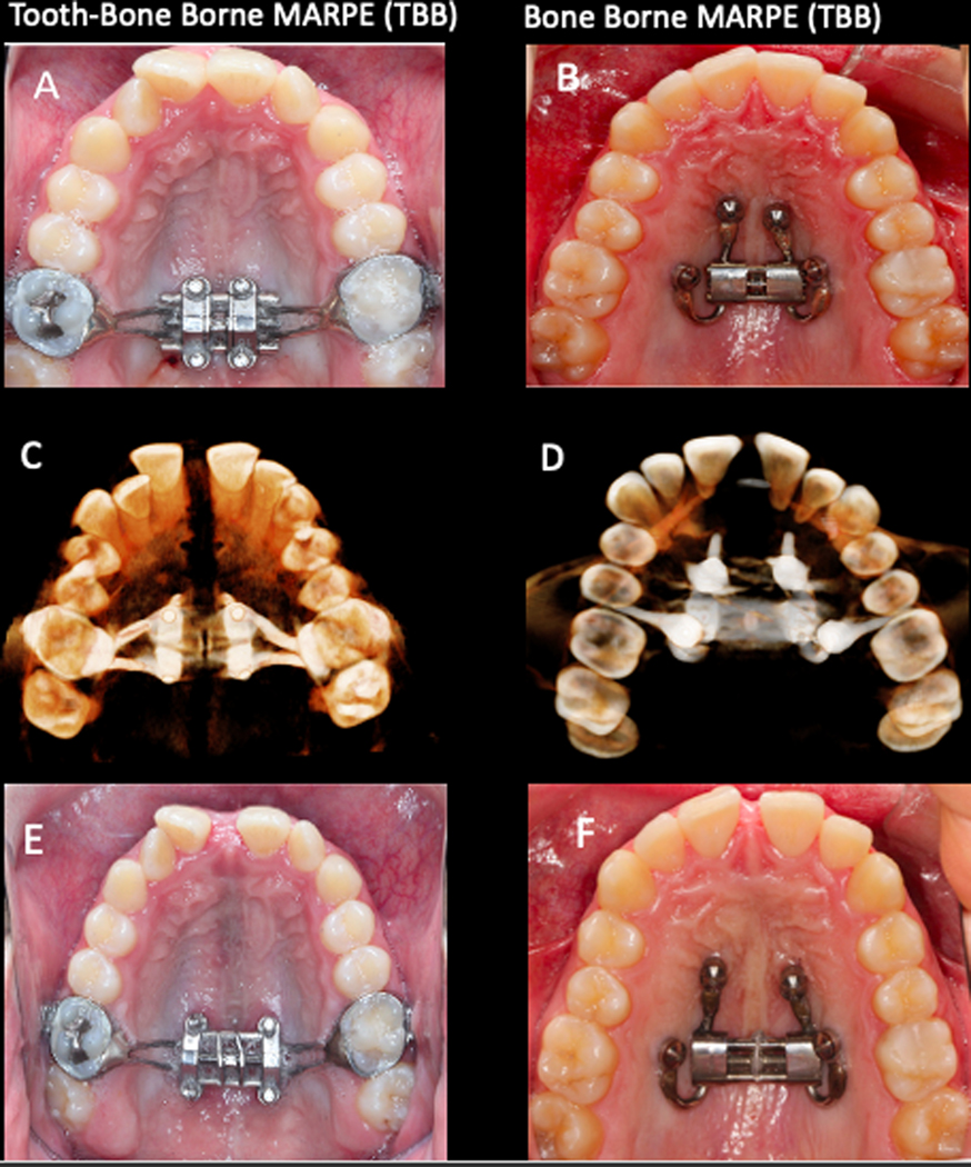
A and B, Maxillary occlusal view depicting the designs of the expanders before the activation (T1): A, TBB; B, BB. C and D, 3D rendering of the CBCT scan with appliance in place at T2 in an inferior view: C, TBB; D, BB. E and F, Maxillary occlusal view showing the end of the expansion with the appliances still in place: E, TBB; F, BB.
Table I.
Sample demographics, maturational stage, and maxillary widths at baseline (T1) in Bone-Borne (BB) Expander Group and Tooth-Bone Borne (TBB) Expander Group.
| Variable | Bone-Borne Expander n=15 | Tooth-Bone Borne Expander n=15 | P value | |
|---|---|---|---|---|
| Mean (SD) | Mean (SD) | |||
| Initial Age (y) | 18.8 (4.7): max. 29; min. 13 | 18.4 (5.9): max. 28.8; min. 8.8 | 0.839† | |
| Female | 19.1 (5.7) | 15.5 (6.0) | 0.155† | |
| Male | 18.6 (3.7) | 21.9 (3.5) | 0.260† | |
| MPS | C(n=8), D(n=7) | C (n=6), D (n=9) | 0.715§ | |
| CVM | 4(n=6), 5 and 6 (n=9) | 4 (n=5), 5 and 6 (n=10) | 1.000§ | |
| Ethnicity | Caucasian (n=15) | Caucasian (n=7) Asian (n=8) | 0.002§ | |
| Sex | Female | 9 (60%) | 8 (53,3%) |
1.000 § |
| Male | 6 (40%) | 7 (47,7 %) | ||
| Or R -Or L | 70.4 (8.1) | 66.5 (6.2) | 0.288† | |
| Zyg R -Zyg L | 82.9 (5.5) | 85.3 (4.9) | 0.315† | |
| NC R -NC L | 18.8 (1.6) | 21.9 (2.1) | 0.000† | |
| PF R -PF L | 28.8 (2.8) | 29.8 (2.0) | 0.277† | |
| M R -M L | 47.4 (5.6) | 51.7 (5.2) | 0.034† | |
| C R -C L | 33.5 (5.2) | 34.6 (4.7) | 0.551† | |
t-test;
Fisher exact test; Or, orbitale; Zyg, zygomatic; NC, nasal cavity; PF, palatine foramen; M, first permanent molars; C, permanent canines; R, right; L, left.
An initial CBCT scan was obtained before each patient underwent an orthodontic protocol in which the first step was maxillary expansion; a second CBCT image was taken at the completion of the expansion with the expander still in place or at the day of removal of the expander (T2). An average of 5.4 ± 3.4 months and 6.2 ± 2.1 months had elapsed between the T1 and the T2 scans of Group TBB (tooth-bone borne) and Group BB (bone-borne) respectively.
Treatment Sample.
Patients were treated between 2015 and 2020. The inclusion criteria were as follows:
Transverse skeletal maxillary discrepancy treated with tooth-bone borne or bone-bone expander. The transverse discrepancy was determined using the maxillomandibular differential index.21
No previous orthodontic treatment.
No history of trauma, or oral/craniofacial surgery.
No systemic disease
Adequate scan quality without movement artefacts
Types of expanders.
The tooth-bone borne (TBB) expander consisted of a central expansion jackscrew with four attached arms soldered to orthodontic bands placed on the maxillary first molars (Fig. 1 A). The addition of four sheaths welded to the body of the central expansion jackscrew allowed for the placement of the miniscrews in the palate. The miniscrews were 1.8 mm in diameter and varied from 8 to 12 mm in length, depending on what was required to achieve bicortical engagement. The palatal mini screws were placed symmetrically and parallel to the midpalatal suture. The miniscrews also were positioned posteriorly without extending into the palatine process (maintaining bony anchorage in the hard palate maximizes orthopedic forces to the pterygoid plates). The jackscrew was placed as close as possible to soft tissues, without impingement to avoid entrapment of food particles.
The bone- borne (BB) expander design used in the other group of patients included 4 miniscrews. Two miniscrews were placed in the anterior area of the palate, at the level of the third rugae. The two other miniscrews were inserted between the second premolar and the first molar (where the root distance is more favorable), at 6–8 mm from the alveolar crest (Fig. 1 B). If anatomic conditions prevented placement of the miniscrew such an ideal position, an alternative site was selected at the level of the second premolar between the nasal and sinus cortical bone, with the miniscrew having a more vertical inclination. Miniscrews used in Group BB varied between 9 and 15 mm in length, while the diameter was 2 mm for all patients (Spider Screw; Hdc, Thiene, Italy). For each patient, 2 insertion guides were designed and 3-dimensionally printed, including 2 sleeves each in cross position: one guide included an anterior-left and posterior-right sleeves and the other an anterior-right and posterior-left sleeve.
Treatment Protocol.
After a chlorhexidine gluconate oral rinse was administered, a preliminary guide-fitting check was performed. Digital insertion planning of the miniscrew is shown in figure 2. Local anesthesia then was applied corresponding to the palatal insertion sites. To improve procedure precision and surgery ergonomics, guides were fixed to the teeth using a fluid resin. All miniscrews insertion began by first using a pilot drill use for cortical perforation. The pick-up to insert miniscrews included a vertical stop, that in combination with the sleeve edge, reproduced the digitally planned screws height exactly.
Figure 2.

Digital insertion planning of the miniscrew.
All miniscrews were placed with an insertion at a torque of between 15 and 30 Newton/centimeter (N/cm) using a low-speed handpiece. After the guide removal the bone-borne expander was placed.
The insertion of a 4-miniscrews expansion device can be difficult because of the differing angulation of each screw’s axis of insertion (i.e., 3 different axes) and because of the undercut generated by the posterior miniscrews. The bone-borne expander was placed with the midline screw expanded 0.8 mm before insertion. The device then was closed completely and the fixation screws were tightened against to the skeletal anchorage device.
Activation protocol for all subjects began 2 weeks after the placement of the miniscrews.22 Patients were taught how to turn the jackscrew; furthermore, they were shown how to maintain proper oral hygiene. Patients were seen at regular intervals during which the number of turns was recorded and the patient could be monitored for any adverse events. The activation protocol was 2 activations per day (one in the morning and one in the evening) until the desired amount of expansion was reached. The expansion was concluded when the lingual cusp of the maxillary molar contacted the buccal cusps of the lower molars. If the expansion occurred asymmetrically, it was stopped according to the side that expanded more.
Skeletal maturation of each subject was assessed using the cervical vertebra maturation (CVM)23 and midpalatal suture maturation (MPM)24 methods.
Data Collection and Analysis Overview
The CBCT scans were taken before treatment (T1) and after completion of maxillary expansion (T2). The generated DICOM files were converted to NIFTI files, which then that were used in the open-source software ITK-SNAP.25 All the image analysis steps were performed by one examiner, and each step was completed on all subjects before moving to the next step. Subsequently, 3D image analysis was performed through the following steps26:
Construction of 3D volumetric label maps (segmentation) and 3D surface models of T1 scans: automatic segmentations were generated in the 3D Slicer software using the ‘Segment Editor’ extension. Then, using the ITK-SNAP software, contours of the segmentation were edited, cropped, and cleaned. Next, using ‘Model Maker’ in the 3D Slicer27 software, the T1 segmentation was converted to a 3D surface model.
Head Orientation using ‘Transforms’ extension: the 3D Slicer software provides a fixed 3D coordinate system with three orthogonal planes denoted by yellow, red, and green colors, representing sagittal, axial and coronal planes, respectively. These planes were used as a reference to orient (translate and or rotate) the T1 model of each patient using Glabella, Crista Galli and Basion used to define the midsagittal plane, and bilateral structures of Orbitale and Porion (Frankfort horizontal plane) utilized to define the axial plane.26
Manual approximation of T1 and T2 scans using the ‘Transform’ extension in the 3D Slicer software: The .nifti scans of the T2 were translated and rotated manually to superimpose the T1 and T2 anterior cranial bases.
Construction of 3D volumetric label maps of the approximated T2 scans: the same procedure described in step #1 was used to construct T2 segmentations.
Voxel-based registration of T1 and T2 scans using the cranial base as reference: the 3D voxel-based registration (‘CMF Reg’ extension in the 3D Slicer software) was used to align the T1 and T2 scans automatically by using corresponding voxels in the cranial base to achieve a reliable and reproducible superimposition of the 2 time points scans of each patient. Once this automated voxel-based registration was completed, the registered files (scans and segmentations) were used for subsequent steps.
Pre-labeling landmarks in the ITK-SNAP software: anatomic landmarks of interest described by Al Turkestani et al22 were “pre-labeled”28 in the ITK-SNAP software on the registered T1 and T2 segmentations simultaneously. Sagittal, axial and coronal slices of the greyscale image and the 3D reconstruction of the image were used for landmark positioning.
Generation of 3D Models in 3D Slicer: using the “Model Maker” extension in the 3D Slicer software, 3D surface models were generated from the segmented head and pre-labeled landmarks at T1 and T2 for each patient.
Landmark-based quantitative assessment: using the “3QDC” extension in the 3D Slicer software, landmarks were placed on the pre-labeled models (Fig. 3), and displacement of landmarks were reported in anterior-posterior, superior-inferior and 3D directions. Maxillary lateral displacements were measured by the difference between T2 and T1 width at the level of the orbit, zygoma, nasal cavity, palatine foramen, upper first molar and canines. For measurement of maxillary anterior-posterior, superior-inferior and 3D displacements, midpoints were generated for each bilateral landmark and then the difference was taken from T1-T2. Angular measurements evaluated the palatal plane changes, angle formed by the right and left orbitale-zygomatic lines in the anterior view and upper first molar and canine torque.
Generation of semitransparent overlays and color maps for visualization: semitransparent overlays of the T1 and T2 models were created for visualization (Fig. 4)
Figure 3.

3D models showing the pre-labeled landmarks (red) utilized in the study. A. Frontal view displays orbitale (Or), nasal cavity (NC), infrazygomatic (IZyg), anterior nasal spine (ANS), anterior concavity of the maxilla (A-point) and permanent canine cusp tip(C). B. Right lateral view depicts canine root apex (Ć), canine cusp tip (C), first molar root apex (M´), first molar cusp tip (M) anterior nasal spine (ANS), and anterior concavity of the maxilla (A-point). C. Inferior view shows canine cusp tip (C), first molar cusp tip (M), palatine foramen (PF), and posterior nasal spine (PNS).
Figure 4.

Semi-transparent 3D surface model overlays of T1 and T2 show skeletal changes in the Bone-Borne MARPE (BB) and Tooth-Bone Borne MARPE (TBB) group from pre-treatment (T1; shown in white) to post-treatment (T2; shown in red) in anterior, posterior, superior and inferior views.
Statistical Analysis
The sample size calculation estimated that a minimum of 15 patients in each group was needed based on a power of 0.80, an alpha of 0.05, mean difference of 1.5 mm for lateral displacement of the nasal cavity and a pooled standard deviation derived from the study by Oh et al12 of 1.4 mm.
Normal distribution of the variables was tested using Shapiro-Wilk tests. Inter-group comparisons for categorical and continuous variables were tested with Fisher exact tests and Independent-sample t tests, respectively. Statistical analyses were performed using IBM SPSS Statistics for Mac, version 27 (Armond, NY, IBM Corp.) The level of significance considered was 5%.
RESULTS
Figure 5 illustrated the treatment changes in Group BB and Group TBB, respectively. In the Group TBB 5 patients were classified as CVM 4, 5 patients as CVM 5 and 5 patients as CVM 6. In Group BB group, 6 patients were classified as CVM 4 and 9 patients as CVM 5. In the Group TBB, 6 patients were classified as stage C of midpalatal maturation and 9 patients were classified as stage D. In Group BB 8 patients were classified as stage C while 7 patients were classified as stage D. For the statistical comparison with Fisher exact test, postpubertal CVM stage 5 and 6 were grouped together.
Figure 5.

CBCT scan overlays of T1 and T2 axial slices at the palatal and sinus level in BB and TBB groups showing both symmetric and the asymmetric expansion in both groups.
Table I shows the mean, standard deviations, and significance of all tested variables between Group BB and Group TBB at the baseline. No significant between-group differences were found for any of variables with the exception of the nasal cavity and of the first molar width, both of which were significantly larger in Group TBB.
Regarding post-treatment changes shown in Table II, an increase in the transverse skeletal dimension was found in all the tested variables; generally, the increase was greater in Group BB than in the Group TBB. The transverse skeletal dimension after the expansion was significantly different between the BB group and the TBB group at the orbitale and nasal cavity levels. The transverse skeletal expansion at the orbitale was 4.4 ± 2.4 mm in Group BB and 1.0 ± 0.8 mm in the Group TBB. Expansion of the nasal cavity was 4.4 ± 2.3 mm and 2.3 ± 1.5 mm, in the BB and TBB groups, respectively. In contrast, the transverse dental changes did not vary significantly between the groups at the molar level; the intermolar width increase the at the molar was 4.8 ± 2.7 mm and 4.4 ± 2.6 mm in Group BB and Group TBB, respectively. Of interest, significantly greater expansion was observed at the canine level in Group BB (4.8 ± 2.6 mm) than in Group TBB (2.8 ± 2.0 mm).
Table II.
Comparisons of skeletal and dental changes in patients treated with Bone-Borne Expander and Tooth-Bone Borne Expander (t- Test).
| Variable | Bone borne Expander n=15 Mean (SD) | Tooth-Bone Expander n=15 Mean (SD) | P value | |
|---|---|---|---|---|
|
Lateral Displacements (3D distance, mm) |
OrR-OrL | 4.4 (2.4) | 1.0 (0.8) | 0.000 |
| ZygR-ZygL | 4.0 (2.8) | 2.8 (1.9) | 0.279 | |
| NCR-NCL | 4.4 (2.3) | 2.3 (1.5) | 0.005 * | |
| PFR-PFL | 3.0 (1.7) | 2.6 (1.6) | 0.487 | |
| MR-ML | 4.8 (2.7) | 4.4 (2.6) | 0.736 | |
| CR-CL | 4.8 (2.6) | 2.8 (2.0) | 0.031 * | |
|
Sagittal Displacements (AP distance, mm) |
Orm | 0.1 (1.1) | 0.2 (0.7) | 0.774 |
| Zygm | 0.7 (1.0) | 0.1 (1.1) | 0.247 | |
| NCm | 0.4 (0.8) | 0.3 (0.5) | 0.564 | |
| PFm | 0.4 (1.1) | −0.2 (0.4) | 0.064 | |
| Mm | 0.7 (1.2) | 1.2 (1.1) | 0.293 | |
| Cm | 1.0 (1.3) | 0.7 (0.8) | 0.508 | |
| ANS | −1.4 (2.0) | 0.4 (1.3) | 0.009 * | |
| PNS | 1.6 (1.1) | 1.5 (1.8) | 0.881 | |
| Point-A | −0.5 (1.8) | 0.01 (0.5) | 0.315 | |
|
Vertical Displacements (SI distance, mm) |
Orm | −0.2 (0.7) | −0.01 (0.3) | 0.523 |
| Zygm | 0.6 (0.7) | −0.2 (0.7) | 0.030 * | |
| NCm | −0.3 (0.7) | −1.2(1.0) | 0.008 * | |
| PFm | −0.4 (1.0) | −1.1 (1.1) | 0.060 | |
| Mm | −0.6 (1.1) | −0.3 (0.9) | 0.533 | |
| Cm | −0.5 (1.0) | −1.0 (1.1) | 0.272 | |
| ANS | −0.4 (1.7) | −0.7 (0.5) | 0.513 | |
| PNS | −0.5 (1.1) | −1.0 (1.3) | 0.298 | |
| Point-A | −0.3 (1.0) | −1.4 (0.8) | 0.003 * | |
|
Angular Changes (degree) |
ANS-PNS | 0.01 (2.0) | 1.3 (0.9) | 0.056 |
| OrR-ZygR – OrL-ZygL | 8.7 (7.2) | 4.2 (4.1) | 0.172 | |
| MR-M’R - M”R-M’’’R | 1.8 (4.0) | 3.5 (3.7) | 0.267 | |
| ML-M’L - M’’L-M’’’L | 1.6 (4.7) | 3.2 (2.9) | 0.277 | |
| CR-C’R - C’’R-C’’’R | 0.5 (2.7) | 2.4 (2.2) | 0.053 | |
| CL-C’L – C’’L-C’’’L | 1.1 (2.6) | 1.4 (1.8) | 0.390 | |
|
Ratio of skeletal
versus dental changes |
PFR-PFL/ MR-ML |
0.77 (0.74) | 0.67 (0.45) | 0.648 |
Values were compared to the control group and statistical significance was determined to be present at
P value < 0.05. Abbreviation: SD, standard deviation; AP, anterior-posterior; SI, superior-inferior; Or, orbitale; NC, nasal cavity; PF, palatine foramen; Zyg, zygomatic; M, first permanent molars cusp tip; C, permanent canine cusp tip; ANS, anterior nasal spine; PNS, posterior nasal spine; M´, first permanent molars root apex; Ć, permanent canines root apex; M’’, T2 permanent molars cusp tip; C’’, T2 permanent canine cusp tip, M’’’, T2 permanent molars root apex; C’’’, T2 permanent canines root apex, m, midpoint; R, right; L, left.
Regarding vertical and sagittal displacements, small insignificant forward and downward movements were observed at the level of orbitale, palatine foramen, maxillary first molar, canine cusp tip and PNS in both groups. At the zygoma, nasal cavity and Point A, small and insignificant forward movement was found in both groups with greater downward movement in Group BB. The differences between the groups at the zygoma was 0.8 ± 0.0 mm, 0.9 ± 0.3 mm at the nasal cavity and 1.1 ± 0.2 at Point A; p values were 0.03, 0.008 and 0.003, respectively. Conversely, ANS presented small and insignificant downward displacement in both group with greater forward movement in Group TBB group. The forward displacement was −1.4 ± 2.0 mm in Group TBB and 0.4± 1.3 mm in Group BB (negative value indicate a posterior displacement).
Regarding angular measurements, changes in the palatal plane angle were small in both groups (0.01 ± 2.0 degrees and 1.3 ± 0.9 degrees in the BB and TBB groups respectively). Both groups showed an increase in the angles between right and left orbitale-zygomatic lines from pre- to post- treatment; in Group BB the increase was twice that occurring in Group TBB (8.7 ± 7.2 degrees in Group BB and 4.2 ± 4.1 degrees in the Group TBB).
The angular changes in the maxillary first molar and the maxillary permanent canine resulted in buccal tipping of the crown. The slight buccal tipping after the expansion at the maxillary first molar was approximately 1.7 degrees in Group BB and 3.5 degrees in Group TBB; at the permanent canine the buccal tipping after the expansion was approximately 1 degree in the BB group and 2 degrees in the TBB group.
No case of mini-screw failure or appliance loss were observed and 56% and 44% of asymmetric expansion was observed in BB and TBB groups respectively.
Intraclass Correlation Coefficient (ICC) was used to assess intra-observer repeatability and it was calculated both for linear and angular (linear:0.85; angular: 0.91) measurement.
Finally, in order to calculate the ratio of skeletal to dental expansion, the amount of expansion at the palatine foramen was divided by that at the first molar cusps. No statistically significant difference was found between the 2 groups with the BB group showing 77% skeletal expansion and 23% dental expansion and the TBB group exhibiting 67% skeletal and 33% dental expansion.
DISCUSSION
Voxel-based superimposition of CBCT scans were used to assess the amount and direction of skeletal and dental changes in the nasomaxillary complex comparing tooth-bone borne (TBB) and bone-borne (BB) expansion. In traditional tooth-borne expansion, strong forces are transmitted through the teeth that often create unwanted dental effects, rather than true skeletal expansion. This observation is particularly true in older patients with more rigid interdigitation of the midpalatal suture.12;29 Alternatively, other types of palatal expanders supported by skeletal anchorage devices have been developed to maximize the skeletal expansion and reduce dental tipping.5 Patients treated with TBB expander, however, still may develop dentoalveolar and periodontal side effects around the supported teeth when compared to patients treated with bone-borne rapid palatal expander (BB). The TBB appliance, however, has the advantages of better rigidity to overcome the sutural tissue resistance.30
Three-dimensional imaging with CBCT and digital dental models allows an accurate assessment of the dentoskeletal effects produced by TBB and BB types of appliances31–32 even though digital dental models do not allow assessment of the sutural opening in different areas of the nasomaxillary complex. Kim et al30 and Al Turkestani et al22 have investigated nasomaxillary 3D dimensional displacements relative to the cranial base in TBB patients. The current study is the first to compare the results of young adult patients treated with a tooth-bone borne expander to those treated with bone-borne expander.
Comparison of Starting Form.
Assessment of the sample demographics, maturational stage, and maxillary widths revealed that the facial morphology of the patients treated with either the TBB or BB expanders were comparable at baseline (Table I). Both groups presented similar number of males and females with similar average chronologic ages. Furthermore, they presented similar distributions of CVM stages and midpalatal suture maturation. The orbital, zygomatic, palatine foramen and canine widths were similar in the two groups, whereas the nasal cavity was approximately 3 mm wider in the Group TBB (21.9 ± 2.1 mm) than in Group BB (18.8 ± 1.6 mm) this was related to different ethnicity; intermolar widths was approximately 4 mm wider in the TBB group (51.7 ± 5.2 mm) than in the BB group (47.4 ± 5.6 mm).
Transversal Skeletal Expansion.
Maxillary skeletal width expansion occurred in both groups, as shown in Table II. This study demonstrated that after expansion, the orbitale was displaced significantly more laterally in Group BB (4.4 ± 2.2 mm) than in Group TBB (1.0 ± 0.8 mm). This increase in width at the orbital level was lesser than at the zygoma, nasal cavity and palatine foramen in the TBB group. On the other hand, in the BB group a statistically significantly greater lateral displacement was observed at orbitale (p=0.00) and at the nasal cavity (p=0.005). The expansion in the TBB group confirms the findings of previous studies26,31 in which the treatment led to less lateral displacement at the orbital level and greater lateral displacement close to the sites of force application, resulting in a superior-inferior pyramidal opening.
Instead, in Group BB, expansion of the maxilla did not follow the pyramidal pattern reported in previous studies22,33 with similar amounts of skeletal expansion observed at orbitale, zygoma and nasal cavity. The palatine foramen in the BB and TBB groups showed a lateral displacement of 3.0 ± 1.7 mm and 2.6 ± 1.6 mm respectively, compared to an average lateral displacement of 4.4 ± 2.3 mm and 2.3 ± 1.5 mm, respectively at the level of the nasal cavity. These findings reveal a relatively parallel sutural opening in a sagittal direction in the Group TBB; however, Group BB group presented a somewhat triangular (V-shaped) opening of the suture that was wider anteriorly as described previously by Colak et al.34 The suture opening is shown in Figure 6.
Figure 6.

3D rendering of CBCT scans at T2 in the BB (A and B) and TBB (C and D) groups shown in anterior (A and C) and right lateral views (B and D). The white arrows point to the circum-maxillary sutures open in both groups.
Sagittal and Vertical Skeletal Changes.
Overall, both groups demonstrated small anteroposterior and vertical movements in the BB and the TBB groups, movement that were not statistically significant. These two groups demonstrated small downward and vertical displacements as well as Song et al.35 reported recently; the BB group showed statistically significantly less vertical displacement at Point A, downward −0.3 ± 1.0 and −1.4 ± 0.8 in the BB and TBB groups respectively. There is lack of evidence of why the A point showed lesser vertical displacement in the BB group, a possible explanation relies on a greater release of the circummaxillary sutures having allowed lesser rotational components during the maxillary expansion, or alternatevily the different A vertical changes could be related to the different opening pattern when observed from a frontal view: more parallel for BB group patients and more triangula shape for TBB group patients.
Transverse Dental Changes.
Marked transverse dental changes were observed in both groups at the level of the maxillary molar and canine levels. These changes were significantly greater in Group BB than in Group TBB at the canine level, respectively (5.0 ± 2.6 mm and 3.1 ± 2.0 mm, p=0.04) but not at the molar level (respectively 4.9 ± 2.7 mm and 4.1 ± 2.5 mm respectively). While there were no statistically significant differences in molar and canine tipping between the two groups, a slightly greater dental tipping was noted in the TBB group. An average of about 4° of buccal crown tipping at the first molar was noted bilaterally, compared to an average of 1.5° of tipping in the BB group. The results of this investigation agree with the finding of previous studies that showed an increase of buccal crown tipping by 2.5° to 4° in the anchorage teeth.22,36,37
Asymmetric expansion.
In our study, asymmetric expansion was observed in 50 % of patients in both groups, where one side expanded more than the other relative to the stable structures of reference registration both at the palatal and sinus level (Fig. 5). Eight patients presented asymmetric expansion in the BB group as did 8 patients in the TBB group. The asymmetric expansion was detected both at the level of the palate and at the level of the sinus in both groups. Figure 5 also clearly illustrates the greater amount of skeletal expansion both at the palate and sinus level in BB group, furthermore, the resultant asymmetry when the expansion is also asymmetric is more evident in the BB group.
In agreement with Kim et al.30, patients treated with TBB and BB appliances may manifest an asymmetric nasomaxillary expansion, a clinical outcome that may result in craniofacial changes. After the expansion, one-half of the maxilla may move and displace more than the contralateral one, leading to an asymmetric palatal expansion; in addition, other circummaxillary sutures may split asymmetrically, due in part by the differences in the resistance of the pterygopalatine and zygomatic buttresses, mechanical bone densities, and biological responses. In that the initial scans were taken before the miniscrews were place, retrospective design of the present study did not allow investigation of whether the position of miniscrews placement was a factor in instances of asymmetric expansion.
Skeletal vs. Dental Expansion and Final Considerations.
No significant difference was found at the intermolar distance changes (P=0.736). However, the molar angular changes in the TBB (3.5° and 3.2°) were twice those that found in the BB (1.8° and 1.6°). Even without statistical significance, it means a tendency of slightly greater posterior skeletal expansion in the BB, as the intermolar (left-to-right) distance was the same between the groups only because the greater buccal tipping of the molars in the TBB. If those teeth did not have present buccal tipping, the molar points (MR and ML) would be placed more palatal, what would led to shorter intermolar distance in the TBB group; maybe, with statistical significance.
The amount of expansion at the palatine foramen was divided by the amount at the first molar cusps to calculate the ratio of skeletal to dental expansion. BB group showed 77% skeletal expansion and 23% dental expansion. Maxillary skeletal expansion in the TBB group presented a smaller ratio (though not statistically significant) with 67% skeletal and 33% dental expansion. Bone-borne expander appears to allow somewhat greater skeletal and fewer dentoalveolar changes compared to the tooth-bone borne appliances, as reported in previous studies.14,5 According to these investigators, the difference between the BB and the TBB groups may be due to the direct effects that the bone-borne expander had on the palate5 rather than on the surrounding maxillary molars used as anchorage for the tooth-bone borne expander. On the other hand, TBB are proposed because they have better rigidity to overcome the sutural tissue resistance with less palatal tissue impingement than occurs with the BB expander, according to previous studies.30
CONCLUSIONS
Considering the results of the present study the following conclusions can be summarized:
Both groups demonstrated skeletal and dental changes, with similar amount of posterior palate expansion.
Greater skeletal versus dental expansion ratio and expansion of the circummaxillary regions was found in Group BB compared to Group TBB.
In addition, 56% and 44% of asymmetric expansion was observed in BB and TBB groups respectively.
ACKNOWLEDGEMENT
This work was funded by grant NIDCR R01 DE024550 and AAOF Dewel Memorial Biomedical Research Award 2020. The authors declare no potential conflicts of interest with respect to the authorship and/or publication of this article.
Footnotes
Authors contribution.
Martina Bazzani: Conceptualization, Formal analysis, Investigation, Methodology, Project administration, Writing original draft. Lucia Cevidanes: Conceptualization, Formal analysis, Investigation, Methodology, Funding acquisition, Project administration, Software, Writing – review & editing. Najla Al Turkestani: Conceptualization, Formal analysis, Investigation, Methodology, Project administration. Fabio Annarumma: Formal analysis, Investigation, Methodology, Writing – review & editing. Craig McMullen: Data curation, Formal analysis, Investigation, Methodology, Project Administration. Antonio Ruellas: Conceptualization, Formal analysis, Investigation, Methodology, Software, Writing – review & editing. Camila Massaro: Formal analysis, Investigation, Methodology, Writing – review & editing. Marcus Rego: Data curation, Writing – review & editing. Marilia Yatabe: Conceptualization, Writing – review & editing. Hera Kim-Berman: Conceptualization, Writing – review & editing. James McNamara Jr: Formal analysis, Investigation, Methodology, Writing – review & editing. Lorenzo Franchi: Formal analysis, Investigation, Methodology, Writing – review & editing. Peter Ngan: Data curation, Conceptualization, Writing – review & editing. Hong He: Data curation, Conceptualization, Writing – review & editing. Fernanda Angelieri: Formal analysis, Investigation, Methodology, Writing – review & editing. Hussein Aghazada: Formal analysis, Investigation, Methodology, Writing – review & editing. Marco Migliorati: Formal analysis, Investigation, Methodology, Writing – review & editing.
Conflict of interest statement. All authors declare that they have no conflicts of interest.
Contributor Information
Martina Bazzani, School of Dentistry, Genova University, Genova, Italy.
Lucia H. S. Cevidanes, Department of Orthodontics and Pediatric Dentistry, School of Dentistry, University of Michigan, Ann Arbor, MI, United States.
Najla N. Al Turkestani, Department of Orthodontics and Pediatric Dentistry, School of Dentistry, University of Michigan, Ann Arbor, MI, United States; Department of Restorative and Aesthetic Dentistry, Faculty of Dentistry, King Abdulaziz University, Jeddah, Saudi Arabia.
Fabio Annarumma, Private Practice of Orthodontics, Piazza Luigi Rizzo 1 Ciampino, Rome, Italy.
Craig McMullen, Private Practice of Orthodontics, Brighton, Michigan USA.
Antonio C. O. Ruellas, Department of Orthodontics, School of Dentistry, Federal University of Rio de Janeiro, Rio de Janeiro, Brazil.
Camila Massaro, Department of Orthodontics, Bauru Dental School, University of São Paulo, São Paulo, Brazil.
Marcus V. N. N. Rego, Department of Orthodontics, Centero Universitário Uninovafapi, Teresina, Piaui, Brazil.
Marilia S. Yatabe, Department of Orthodontics and Pediatric Dentistry, School of Dentistry, University of Michigan, Ann Arbor, MI, United States.
Hera Kim-Berman, Department of Orthodontics and Pediatric Dentistry, School of Dentistry, University of Michigan, Ann Arbor, MI, United States.
James A. McNamara, Jr, Department of Orthodontics and Pediatric Dentistry, School of Dentistry, University of Michigan, Ann Arbor, MI, United States.
Lorenzo Franchi, Department of Surgery and Translational Medicine, University of Florence, Via del Ponte, di Mezzo, Florence, Italy.
Peter Ngan, Department of Orthodontics, West Virginia University School of Dentistry, Morgantown, WV, United States.
Hong He, Department of Orthodontics, School & Hospital of Stomatology, Wuhan University, Wuhan, China.
Fernanda Angelieri, Department of Orthodontics, Methodist University of São Paulo, São Paulo, Brazil.
Hussein Aghazada, Private Practice of orthodontics, Piazzale Ardeatino, 1G, 00154 Rome, Italy.
Marco Migliorati, Department of Orthodontics, Genoa University School of Dentistry, Genova, GE, Italy.
Data availability statement:
The data that support the findings of this study are available from the corresponding author upon reasonable request
REFERENCES
- 1.Proffit WR, Fields HW Jr, Moray LJ. Prevalence of malocclusion and orthodontic treatment need in the United States: estimates from the NHANES III survey. Int J Adult Orthod Orthogn Surg. 1998;13(2):97–106. [PubMed] [Google Scholar]
- 2.Lagravère MO, Carey J, Heo G, Toogood RW, Major PW. Transverse, vertical, and anteroposterior changes from bone-anchored maxillary expansion vs traditional rapid maxillary expansion: a randomized clinical trial. Am J Orthod Dentofacial Orthop. 2010;137(3):304.e1–12. [DOI] [PubMed] [Google Scholar]
- 3.Angell DH. Treatment of irregularity of the permanent or adult teeth. Dent Cosmos. 1860; 1:540–544. [Google Scholar]
- 4.Lagravère MO, Major PW, Flores-Mir C. Long-term skeletal changes with rapid maxillary expansion: a systematic review. Angle Orthod. 2005;75(6):1046–52. [DOI] [PubMed] [Google Scholar]
- 5.Krüsi M, Eliades T, Papageorgiou SN. Are there benefits from using bone-borne maxillary expansion instead of tooth-borne maxillary expansion? A systematic review with meta-analysis. Prog Orthod. 2019. 25;20(1):9. [DOI] [PMC free article] [PubMed] [Google Scholar]
- 6.Haas AJ. Rapid expansion of the maxillary dental arch and nasal cavity by opening the midpalatal suture. Angle Orthod. 1961; 31(2):73–90. [Google Scholar]
- 7.Biederman W. A hygienic appliance for rapid expansion. JPO J Pract Orthod. 1968;2(2):67–70. [PubMed] [Google Scholar]
- 8.Annarumma F, Posadino M, De Mari A, Drago S, Aghazada H, Gravina GM, Qorri E, Silvestrini-Biavati A, Migliorati M. Skeletal and dental changes after maxillary expansion with a bone-borne appliance in young and late adolescent patients. Am J Orthod Dentofacial Orthop. 2021;159(4):e363–e375. [DOI] [PubMed] [Google Scholar]
- 9.Migliorati M, Drago S, Schiavetti I, Olivero F, Barberis F, Lagazzo A, Capurro M, Silvestrini-Biavati A, Benedicenti S. Orthodontic miniscrews: an experimental campaign on primary stability and bone properties. Eur J Orthod. 2015;37(5):531–8. [DOI] [PubMed] [Google Scholar]
- 10.Karagkiolidou A, Ludwig B, Pazera P, Gkantidis N, Pandis N, Katsaros C. Survival of palatal miniscrews used for orthodontic appliance anchorage: a retrospective cohort study. Am J Orthod Dentofacial Orthop. 2013;143(6):767–72. [DOI] [PubMed] [Google Scholar]
- 11.Moon W. Class III treatment by combing facemask (FM) and maxillary skeletal expander (MSE). Semin. Orthod. 2018; 24:95–107. [Google Scholar]
- 12.Oh H, Park J, Lagravère -Vich MO. Comparison of traditional RPE with two types of micro-implant assisted RPE: CBCT study. Semin Orthod. 2019; 25:60–68. 10.1053/j.sodo.2019.02.007. [DOI] [Google Scholar]
- 13.Mosleh MI, Kaddah MA, Abd ElSayed FA, ElSayed HS. Comparison of transverse changes during maxillary expansion with 4-point bone-borne and tooth-borne maxillary expanders. Am J Orthod Dentofacial Orthop. 2015;148(4):599–607. [DOI] [PubMed] [Google Scholar]
- 14.Lin L, Ahn HW, Kim SJ, Moon SC, Kim SH, Nelson G. Tooth-borne vs bone-borne rapid maxillary expanders in late adolescence. Angle Orthod. 2015; 85(2):253–62. [DOI] [PMC free article] [PubMed] [Google Scholar]
- 15.Handelman CS, Wang L, BeGole EA, Haas AJ. Nonsurgical rapid maxillary expansion in adults: report on 47 cases using the Haas expander. Angle Orthod. 2000;70(2):129–44. [DOI] [PubMed] [Google Scholar]
- 16.Yildirim M, Akin M. Comparison of root resorption after bone-borne and tooth-borne rapid maxillary expansion evaluated with the use of microtomography. Am J Orthod Dentofacial Orthop. 2019;155(2):182–190. [DOI] [PubMed] [Google Scholar]
- 17.Winsauer H, Vlachojannis J, Winsauer C, Ludwig B, Walter A. A bone-borne appliance for rapid maxillary expansion. J Clin Orthod. 2013;47(6):375–81. [PubMed] [Google Scholar]
- 18.Mozzo P, Procacci C, Tacconi A, Martini PT, Andreis IA. A new volumetric CT machine for dental imaging based on the cone-beam technique: preliminary results. Eur Radiol. 1998;8(9):1558–64. [DOI] [PubMed] [Google Scholar]
- 19.Lagravère MO, Carey J, Toogood RW, Major PW. Three-dimensional accuracy of measurements made with software on cone-beam computed tomography images. Am J Orthod Dentofacial Orthop. 2008;134(1):112–6. [DOI] [PubMed] [Google Scholar]
- 20.Swennen GRJ, Schutyser F, Hausamen JE. Three-dimensional cephalometry: color atlas and manual. Heidenberg, Germany: Springer; 2005. [Google Scholar]
- 21.Vanarsdall RL Jr. Transverse dimension and long-term stability. Semin Orthod. 1999;5(3):171–80. [DOI] [PubMed] [Google Scholar]
- 22.Al Turkestani N, McMullen C, Ruellas ACO, Massaro C, Rego MVNN, Yatabe M, Kim-Berman H, McNamara JA Jr, Angelieri F, Franchi L, Ngan P, He H, Cevidanes LHS. Three-dimensional evaluation of skeletal and dental effects of treatment with Maxillary Skeletal Expansion (MARPE). Am J Orthod Dentofacial Orthop, in press. [DOI] [PMC free article] [PubMed]
- 23.McNamara JA Jr, Franchi L. The cervical vertebral maturation method: A user’s guide. Angle Orthod. 2018;88(2):133–143. [DOI] [PMC free article] [PubMed] [Google Scholar]
- 24.Angelieri F, Cevidanes L, Franchi L, Gonçalves J, Benavides E, McNamara JA Jr., Midpalatal suture maturation: Classification method for individual assessment before rapid maxillary expansion. Am J Orthod Dentofacial Orthop. 2013;144(5):759–769. [DOI] [PMC free article] [PubMed] [Google Scholar]
- 25.ITK-SNAP Home. Itksnap.org. http://itksnap.org/. Published 2020. Accessed October 6, 2020.
- 26.Ruellas AC. Common 3-dimensional coordinate system for assessment of directional changes. Am J Orthod Dentofacial Orthop. 2016; 149(5):645–656. [DOI] [PMC free article] [PubMed] [Google Scholar]
- 27.3D Slicer. Slicer.org. https://www.slicer.org/. Published 2020. Accessed October 6, 2020.
- 28.Ruellas AC, Huanca Ghislanzoni LT, Gomes MR, Danesi C, Lione R, Nguyen T, McNamara JA Jr, Cozza P, Franchi L, Cevidanes LH. Comparison and reproducibility of 2 regions of reference for maxillary regional registration with cone-beam computed tomography. Am J Orthod Dentofacial Orthop. 2016. ;149(4):533–42. [DOI] [PMC free article] [PubMed] [Google Scholar]
- 29.Carlson C, Sung J, McComb RW, Machado AW, Moon W. Microimplant-assisted rapid palatal expansion appliance to orthopedically correct transverse maxillary deficiency in an adult. Am J Orthod Dentofacial Orthop. 2016;149(5):716–28. [DOI] [PubMed] [Google Scholar]
- 30.Kim KA, Oh SH, Kim BH, Kim SJ. Asymmetric nasomaxillary expansion induced by tooth-bone-borne expander producing differential craniofacial changes. Orthod Craniofac Res. 2019;22(4):296–303. [DOI] [PubMed] [Google Scholar]
- 31.Kapila SD, Nervina JM. CBCT in orthodontics: assessment of treatment outcomes and indications for its use. Dentomaxillofac Radiol. 2015;44(1):20140282. [DOI] [PMC free article] [PubMed] [Google Scholar]
- 32.Nakajima A, Sameshima GT, Arai Y, Homme Y, Shimizu N, Dougherty H Sr. Two- and three-dimensional orthodontic imaging using limited cone beam-computed tomography. Angle Orthod. 2005;75(6):895–903. [DOI] [PubMed] [Google Scholar]
- 33.Park JJ, Park YC, Lee KJ, Cha JY, Tahk JH, Choi YJ. Skeletal and dentoalveolar changes after miniscrew-assisted rapid palatal expansion in young adults: A cone-beam computed tomography study. Korean J Orthod. 2017;47(2):77–86. [DOI] [PMC free article] [PubMed] [Google Scholar]
- 34.Colak O, Paredes NA, Elkenawy I, Torres M, Bui J, Jahangiri S, Moon W. Tomographic assessment of palatal suture opening pattern and pterygopalatine suture disarticulation in the axial plane after midfacial skeletal expansion. Prog Orthod. 2020;21(1):21. [DOI] [PMC free article] [PubMed] [Google Scholar]
- 35.Song KT, Park JH, Moon W, Chae JM, Kang KH. Three-dimensional changes of the zygomaticomaxillary complex after mini-implant assisted rapid maxillary expansion. Am J Orthod Dentofacial Orthop. 2019;156(5):653–662 [DOI] [PubMed] [Google Scholar]
- 36.Ngan P. Skeletal, dentoalveolar, and periodontal changes of skeletally matured patients with maxillary deficiency treated with microimplant-assisted rapid palatal expansion appliances: A pilot study. APOS Trends Orthod. 2018; 8(2):71–85. [Google Scholar]
- 37.Moon H-W. Molar inclination and surrounding alveolar bone change relative to the design of bone-borne maxillary expanders: A CBCT study. Angle Orthod. 2020; 90(1):13–22. [DOI] [PMC free article] [PubMed] [Google Scholar]
Associated Data
This section collects any data citations, data availability statements, or supplementary materials included in this article.
Data Availability Statement
The data that support the findings of this study are available from the corresponding author upon reasonable request