

Abstract
Bioprinting is an application of additive manufacturing that can deliver promising results in regenerative medicine. Hydrogels, as the most used materials in bioprinting, are experimentally analyzed to assure printability and suitability for cell culture. Besides hydrogel features, the inner geometry of the microextrusion head might have an equal impact not only on printability but also on cellular viability. In this regard, standard 3D printing nozzles have been widely studied to reduce inner pressure and get faster printings using highly viscous melted polymers. Computational fluid dynamics is a useful tool capable of simulating and predicting the hydrogel behavior when the extruder inner geometry is modified. Hence, the objective of this work is to comparatively study the performance of a standard 3D printing and conical nozzles in a microextrusion bioprinting process through computational simulation. Three bioprinting parameters, namely pressure, velocity, and shear stress, were calculated using the level-set method, considering a 22G conical tip and a 0.4 mm nozzle. Additionally, two microextrusion models, pneumatic and piston-driven, were simulated using dispensing pressure (15 kPa) and volumetric flow (10 mm3/s) as input, respectively. The results showed that the standard nozzle is suitable for bioprinting procedures. Specifically, the inner geometry of the nozzle increases the flow rate, while reducing the dispensing pressure and maintaining similar shear stress compared to the conical tip commonly used in bioprinting.
Keywords: Bioprinting, Computational simulation, Bioink, Nozzle, Level-set method, Non-Newtonian fluid
1. Introduction
209210Bioprinting is one of the most studied applications of additive manufacturing. The combination of novel manufacturing processes with standard tissue engineering protocols is leading to a revolution in the medical field. Bioprinting is formally defined as “the process of producing tissues or organs similar to natural body parts and containing living cells, using 3D printing”[1]. One of the main reasons this technology is widely studied is because it minimizes the rejection risk when cells from the own patient are used in the process[2]. Researchers are using bioprinting to study the generation of vascular, neural, bone, cardiac, skin, or muscle tissues[3,4]. Since each tissue has very specific properties and functionality depending on the role that plays within the body, the procedure in the bioprinting process as well as the main material must be a perfect match with the cells of the target tissue.
Techniques used in bioprinting can be classified according to ASTM standards, as extrusion-based (microextrusion), jetting-based (inkjet, laser-assisted), and vat polymerization stereolithography (SLA)[5], among which microextrusion bioprinting is the most used technique. Microextrusion can be considered a combination of a fluid-dispensing system and an automated robotic system. This technique can be performed pneumatically or mechanically (piston or screw-driven)[6]. While the former facilitates the configuration of bioprinting parameters such as the dispensing pressure, the latter provides a more stable volumetric flow[2,7,8].
Jetting-based bioprinting consists of the noncontact deposition of defined sized droplet into a substrate. There are two main technologies related to jetting-based bioprinting, inkjet and laser-assisted. While the former uses mechanical methods (thermal, piezoelectric, electrostatic, or electrohydrodynamic) to generate controlled size droplets, the latter uses a laser to heat a biomaterial layer, causing a thermal expansion of a tiny portion of the material, forming a droplet that falls into a substrate[9,10].
Finally, vat polymerization, also known as SLA, refers to the photopolymerization of a photocurable liquid, a bioresin, by a specific light source. Depending on the light source and its movement, vat polymerization can be classified as (1) stereolithography (SLA) when the light source is a movable laser beam that directly irradiates the resin; (2) digital light processing (DLP) when a digital micro-mirror device projects a silhouette of the layer; or (3) two-photon polymerization (2PP) when a femtosecond laser emits two photons that excite the resin, causing the polymerization[5].
Some authors[11-13] have reviewed the most commonly used bioprinting techniques. All of them agree that the main advantages are the possibility to use high-viscosity bioinks with high cell density as well as their simple process for microextrusion; the accurate deposition of a small number of cells in a fast process with high cell viability (80%–90%) for inkjet; or the high printing resolution for vat polymerization. Additionally, the main disadvantages of the previous bioprinting techniques are the relatively low printing speed with moderate cell viability (40%–80%) for microextrusion and the limited bioink and cell density, as well as the complexity of the system for inkjet, and harmful wavelengths for photopolymerization, complex relationships between printing parameters and reduced number of nontoxic materials available for vat polymerization. Despite its low printing speed, microextrusion is the most versatile technique and allows the use of highly viscous materials with high cell density[2,7,8].
Regarding bioprinting materials, the interaction between the material and cell viability[14,15], printability[16-18], crosslinking[19-21], or shape fidelity[22,23] have been analyzed in many studies. Hydrogels are the most common material in microextrusion bioprinting. Despite they are mainly composed of water, their usual behavior is closer to a shearthinning non-Newtonian material. In this type of materials, the viscosity plays a major role in how the material flows. In general, the higher the viscosity is, the higher the inner pressure and the shear stress are, meaning that higher force is needed to obtain a proper flow. Previous studies showed that inner pressure and shear stress can provoke cell lysis, i.e., cells die due to the break of their cellular membrane[24-26]. As for viscosity, high values are usually required to achieve the best shape fidelity[27]. Viscosity is also sensitive to temperature[28-31] and it is widely studied together with the concentration of components to assure printability[17,18,32]. So as viscosity affects the nozzle inner flow and cellular viability, it is a key factor to observe[33,34]. Therefore, the actual behavior of the bioink flowing inside the nozzle is an important aspect to determine but difficult to control in experimental tests. With the small nozzle size, the nozzle inner geometry greatly influences the material flow. Additionally, the smaller is the nozzle, the more difficult it is to sensorize it and to experimentally measure the flow without disturbing it or using any scaling technique. There are many studies about bioprinting hydrogels but most of them are experimental and focused on bioprinting results while the study of crucial inner parameters such as pressure or shear stress is often neglected or overlooked[18,35]. For this reason, computational simulations were proposed as a helpful tool to obtain hard-to-measure, bioprinting inner parameters[36,37]. Previous studies showed that cell viability was highly impacted by the nozzle inner pressure, and even more by the shear stress[24]. In this sense, Blaeser et al.[38] classified the shear stress ranges that affect cellular viability211 into low shear stress (<5 kPa), that has high cellular viability up to 96%; medium shear stress (5–10 kPa), with a cellular viability of 91%; and high shear stress (>10 kPa), with a cell viability of 76%.
Computational simulation is currently used to study different features of the bioprinting process, such as shear stress[39], noncommercial nozzle geometries[40-42], bioprinting materials[43], and their tuned rheological properties[37,44]. Regarding the interaction between nozzle geometry and hydrogel flow, two approaches can be followed: either fixing the hydrogel and changing the nozzle geometries[25,41,42,45] or fixing the nozzle geometry and changing the hydrogel properties[37,39,43,46-48]. More complex simulations have been performed to study the generation of droplets for inkjet bioprinting[47,49] or the generation of strands for microextrusion bioprinting[50]. These studies used the two-phase flow level-set model in COMSOL multiphysics to simulate the bioprinting process. On the one hand, results from Liravi et al.[47] and Samanipour et al.[49] showed an experimentally tested droplet generation using a 27G conical tip. On the other hand, Gómez-Blanco et al.[50] studied some inner parameters of the microextrusion process (shear stress, pressure, and velocity), but without experimental validation. Finally, other simulation studies analyzed the flow through a standard 3D printing nozzle and the filament deposition in a fuse deposition modeling process[51,52]. Figure 1 shows both a 22G conical tip and a standard 3D printing nozzle. The main differences between them are the material used, i.e., plastic for the conical tip and brass/stainless steel for the nozzle, and their internal geometry, which can be seen in Figure 2. Typically, the conical tip is optimized for its use in clinical work with low-viscosity materials. On the contrary, 3D printing nozzles are designed and manufactured to reduce the force needed to work with molten plastics, which are considered high-viscosity materials. Nevertheless, to the best of our knowledge, no studies have been performed to analyze the performance of standard 3D printing nozzles with bioprinting materials.
Figure 1.

22G conical tip and a 0.4 mm E3D V6.4 standard 3D printing nozzle.
Figure 2.

Cross-section blueprint (A) and computational model geometry (B) of the 22G conical tip (left) and E3D V6.4 3D printing nozzle (right).
Hence, the working hypothesis is that a standard 3D printing nozzle could improve performance of a conical tip standard bioprinting nozzle. Consequently, the objective of this work is to analyze the performance of an E3D V6 standard nozzle compared with a 22G conical tip for a microextrusion bioprinting process using a commercial bioink as hydrogel. Specifically, inlet (or dispensing) and outlet pressure, volumetric flow, outlet velocity and maximum shear stress were analyzed. To study the feasibility of the proposed nozzle, two different simulation inlets were configured to simulate pneumatic and piston-driven microextrusion bioprinting.
2. Materials and methods
2.1. Computational model and simulation
The methodology used in this work follows the geometrical and computational models, the mathematical solvers, and the hydrogel features defined by Gómez-Blanco et al.[50]
Specifically, two 2D axisymmetric geometrical models were created and simulated in COMSOL Multiphysics 5.4a (COMSOL Inc., Burlington, MA, USA, 2018) using a two-phase flow level-set interface approach. These two geometrical models were a bioprinting 22G conical tip (Cellink, BICO Company, Gothenburg, Sweden) and a 3D printing E3D V6.4 nozzle (E3D Online, Chalgrove, Oxfordshire, UK), named hereinafter as Cone and Nozzle, respectively. The geometries were chosen for two main reasons. The first is that 0.4 mm is the most common gauge/diameter for both printheads. The second is related to the different overall lengths of the nozzle and tip, and the different lengths and angles of the internal tapered wall. Fluid dynamics theory suggests that straight tubes have a constant distribution of shear stress in the wall. On the other hand, abrupt changes in the wall angle cause a distortion of the shear stress distribution and values. The geometries were obtained by experimental measurement for the Cone and from blueprints for the Nozzle[53]. In Figure 2, blueprint cross sections of both geometries (A) are shown for better understanding of the modeled inner geometries used in the simulations.
212Each simulation considered two domains: the first one referred to the hydrogel inside of the Cone or Nozzle, and the second one referred to air. In Figure 2, the geometrical models of the simulations (B) with the boundaries considered and the domains (blue for hydrogel and gray for air) are represented. Model inlets were configured to two approaches: a pneumatic process with 15 kPa inlet pressure, as recommended by Cellink[54], and a piston-driven process with 10 mm3/s volumetric inlet flow.
In this work, Cellink bioink (Cellink USA) was simulated at 37°C with the following fitted potential law:
| (I) |
where μ is the dynamic viscosity (Pa·s) and is the shear rate (s−1).
Regarding the simulations, four different simulations were performed. A 10 s simulation with a 1 ms step was done for each geometrical model and inlet configuration. The simulation study was composed by a phase initialization and time-dependent steps.
A laminar flow based on a low Reynolds number (Re ≅ 0.4) was assumed in the simulations, according to a previous study[50], where simulations formed a falling drop with a later accumulation of material until it reached the tip.
2.2. Experimental test
Pneumatic simulations were validated through experimental tests to assure that they were accurate within acceptable error ranges, despite the assumed simplifications.213 Our validation tests recreated the experimental validation performed by Liravi et al.[47]. The extruded strand was measured and compared with the simulation results, using the total height and the maximum width of this extruded strand. This indirect validation of our simulations was used due to the small outlet diameter of the Cone and Nozzle that was nearly impossible to measure the pressure or the velocity without disturbing the normal flow and thus modify the results. A Sony Alpha 7 ii (ILCE-7m2) camera with a Sony f 2.8/90 OSS macro was used to record the extruded Cellink Bioink strand with a 1920 × 1080 pixel resolution and 0.5× magnification. The distance between the camera lens and the nozzle tip was 28 cm (focal distance). The microextrusion was performed in Cellink BioX bioprinter with a preset of 15 kPa for inlet pressure. Three videos for each of the four experimental tests were recorded, from which frames were automatically extracted using Open CV and analyzed using ImageJ 1.53e software.
3. Results and discussion
In this section, results obtained for the three analyzed parameters are presented. However, since later accumulation of material is not produced in a real bioprinting procedure because of the X–Y extruder head movement, data are only analyzed until the drop falls, although figures show the full 10 s simulations.
Additionally, the results presented in this section only refer to the 22G conical tip and the 0.4 mm E3D V6.4 3D printing nozzle. It is not possible to generalize the results to other conical tip gauges and nozzle output diameters with the current data. The internal geometry of the conical tips remains constant for gauges smaller than 27G, but some of the internal lengths of the E3D V6.4 3D printing nozzle vary with each output diameter[53].
3.1. Outlet and inlet pressure
Figure 3 shows the outlet pressure measured at end of the Cone and Nozzle for pneumatic and piston-driven simulations.
Figure 3.

Outlet pressure (Pa) of pneumatic and piston-driven simulations and the two analyzed nozzles.
Analyzing the pressure of pneumatic simulations, using 15 kPa as the simulation inlet, the pressure evolution in both geometries is similar, showing a low-pressure peak which is explained by the formation and falling of a drop, as detected in previous works[50]. Therefore, the maximum outlet pressure before the low-pressure peak reaches 2.75 and 1.54 kPa for the Nozzle and Cone, respectively. The outlet pressure of the Nozzle is approximately twice that of the Cone. Regarding timing, the peaks are in 0.586 and 6.860 s for Nozzle and Cone, respectively. The difference in times might be caused by the total amount of extruded bioink. In this sense, Figure 4 shows that the flow rate of the Nozzle geometry is higher than that of the Cone. Specifically, the drop volume extruded by the Nozzle is 12.70 mm3, while the one by the Cone is 9.72 mm3 through the same cross-sectional area. So, the Nozzle geometry extrudes approximately 15 times more bioink than the Cone (21.67 vs 1.42 mm3/s). This large difference214 in bioink flow rate might be useful for faster bioprinting while maintaining a recommended dispensing pressure for this specifical bioink. Therefore, the use of Nozzletype microextrusion head in pneumatic bioprinting could partially solve the current challenge of low printing speed for bioprinting[2,7,8,26].
Figure 4.

Extruded volume (mm3) of pneumatic simulations. Extruded volume of piston-driven simulations is not shown in the figure because volumetric flow is set as simulation inlet (10 mm3/s so the extruded volume in 10 s is 100 mm3).
Outlet pressure from piston-driven simulations shows a similar evolution in values and times (Figure 3). Therefore, there were no relevant differences between the Nozzle and Cone maximum pressure values (2.41 and 2.27 kPa), the time when the drop falls (0.928 and 1.208 s) or the low-pressure peak values (250 Pa lower for the Nozzle).
Comparing all simulations, the Nozzle geometry outlet pressure is higher than in the Cone in all cases. However, if only piston-driven simulations are considered, the outlet pressure is nearly the same, as these simulations establish a fixed inlet volumetric flow. Hence, the input or dispensing pressure plays an important role when obtaining the outlet pressure, but in all cases, they vary in a short range with a maximum variation of approximately 2.2 kPa.
The dispensing (or inlet) pressure was fixed by pneumatic simulations at 15 kPa, but piston-driven simulations, where the volumetric flow was fixed, resulted in smaller pressure for the Nozzle (Figure 5).
Figure 5.

Dispensing pressure (kPa) of piston-driven simulations. Pneumatic dispensing pressure is not shown in the figure because it is set as 15 kPa inlet pressure for simulations.
Maximum inlet pressure values are 22.73 kPa and 12.95 kPa for the piston-driven Cone and Nozzle geometries, respectively. The obtained values are consistent with the pneumatic simulation’s extruded volume (Figure 4). The Cone needs an inlet pressure over 15 kPa to achieve the expected extruded volume while the Nozzle requires lower pressure to extrude the same volume. In this sense, the Cone inlet pressure is 1.76 times bigger than the Nozzle pressure. According to Boularaoui et al.[26], the lower the dispensing pressure, the better the cellular viability. Therefore, our results showed that the Nozzle configuration is better for microextrusion bioprinting at least when it comes to inlet pressure.
Our simulation results are also similar to Gómez-Blanco et al.[50], who obtained maximum values in the range of 1.14–1.76 kPa for conical tips using 15 kPa as inlet pressure. Thus, the pressure values are in the range for pneumatic simulations and Cone geometry but not for the rest. Additionally, Reid et al.[42] set the outlet pressure to 1 atm (101 kPa) and obtained maximum inner pressure with an approximate value of 107 kPa. This value can be understood as the inlet pressure, but proper explanation is missing in the article to assure this statement. In this sense, although they obtained 6 kPa of inlet pressure, which seems better than our results, it is difficult to make a fair comparison between both studies due to three main differences in the methodologies. The first one is the selected extrusion material. While the rheological data of the material were properly detailed in this work, they used “a fluid with similar properties to blood” as the bioink without further information. Second, we set an inlet215 volumetric flow equal to 10 mm3/s in our simulations while they set 0.1 mm3/s, which caused an increase in the inlet pressure. Finally, we used a standard 0.4 mm 3D printing nozzle and a 22G (0.4 mm) conical tip, whereas they used a custom-made glass similar to conical tip with an outlet diameter of 60 μm.
The inner pressure, which is the difference between inlet and outlet pressure, is 13.46 and 12.25 kPa for Cone and Nozzle pneumatic simulations, respectively; and 20.46 and 10.54 kPa for Cone and Nozzle piston-driven simulations, respectively. Inner pressure must be carefully analyzed, even though lower inner pressure might be beneficial for cells. If it is a result of very high inlet and outlet pressure, it would still compromise cellular viability. In this sense, Boularaoui et al.[26] concluded that cellular viability is inversely related to dispensing pressure and although they have forewarned of the influence of this parameter, they never defined a threshold value. Thus, according to our results, inner pressure in pneumatic simulations is very similar, but the total extruded volume makes the Nozzle perform better. A similar conclusion can be drawn from piston-driven simulations pressure, as the Nozzle geometry can extrude the same amount of material as the Cone with less inner pressure and half the inlet pressure.
3.2. Outlet velocity
As literally concluded by Boularaoui et al.[26], cell damage appears to be affected by the time of exposure to stress more than the magnitude of the stress itself. Thus, outlet velocity is another important parameter to be analyzed. In this regard, results of maximum velocity obtained in the bioink domain for all simulations can be found in Figure 6. Nozzle simulations had higher velocities than those for the Cone. In all cases, a high-velocity peak was formed, but the peak was only easily noticeable in the simulation for the Nozzle under pneumatic microextrusion. The lowest velocities for each simulation are 1.88 and 38.96 cm/s for Cone and Nozzle pneumatic simulations, respectively, and further 14.50 and 19.20 cm/s for Cone and Nozzle piston-driven simulations, respectively. The differences in velocities can be explained by the different extruded volume (flow rate) in pneumatic simulations and the different geometry in piston-driven simulations. Despite velocity values being similar in piston-driven simulations, the velocity of Nozzle is 32% higher than that of Cone. Hence, according to Boularoui at al.[26] and based on our results, it can be concluded that cells are expected to be under stress for a shorter time in the Nozzle geometry, which might eventually reduce cell damage while increase cellular viability.
Figure 6.
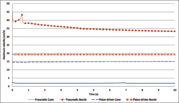
Maximum velocity (cm/s) of pneumatic and piston-driven simulations.
Reid et al.[42] obtained 5.50 and 7.20 cm/s for 60 μm diameter conical and needle tips, respectively, but direct comparison with our results would not be fair enough due to methodological differences, as exposed in the previous subsection about pressure. Additionally, Smith et al.[45] obtained, at the end of their 28G (0.184 mm diameter)216 multiaxial needle, a velocity of 36.70 cm/s. They used a similar material mainly composed of alginate and also fitted to the standard potential law, but their alginate bioink seems to be more viscous than ours. Nevertheless, their inlet was composed of three different needle entrances, and they set one velocity for each entrance (0.4, 1.81, and 6.57 cm/s). Therefore, similar to what happened in Reid et al.’s experiment, results of Smith et al. are not directly comparable to ours due to these major differences in the inlet.
3.3. Shear stress
Shear stress is the most important parameter to determine the cellular viability of any bioprinting process. Boularaoui et al.[26] and Blaeser et al.[38] performed a thorough study of shear stress in bioprinting and both concluded that the shear stress has a direct negative impact on the cellular viability. Additionally, Blaeser et al.[38] also determined that shear stress lower than 5 kPa might not have an important influence on cell survival. Figure 7 shows the shear stress and Figure 8 shows the shear stress distribution for all simulations. We report the worst-case scenario, which corresponds to the highest stress peak for each simulation. Bearing this in mind, the values of shear stress are 455.43 and 242.16 Pa for Nozzle and Cone pneumatic simulations, respectively, and 362.85 and 383.24 Pa for Nozzle and Cone piston-driven simulations, respectively. Based on these results, the Nozzle geometry provokes higher shear stress than the Cone one in all cases. Nevertheless, the maximum difference is approximately 213 Pa and the maximum value of shear stress for all simulations is 455.43 Pa, which are in both cases more than ten times lower than the threshold proposed by Blaeser et al.[38]. In addition, the shear stress distribution has little or no change over the simulation time, and a representation of the shear stress distribution can be seen in Figure 8. In this sense, the shear stress distribution is much more concentrated in the tip of the nozzle than in the conical tip. This means that cells are exposed to high shear stress for a longer time in the conical tip than in the nozzle due to the difference in geometry lengths, which may cause cell viability problems as described by Blaeser et al.[38]. Thus, it can be concluded that both geometries generate a shear stress below what is reported as inappropriate for cells, and both can be used in these conditions for bioprinting.
Figure 7.

Maximum shear stress (Pa) of pneumatic and piston-driven simulations.
Figure 8.

Shear stress distribution on t = 2 of the piston-driven nozzle (A), piston-driven conical tip (B), pneumatic nozzle (C), and pneumatic conical tip (D) simulations.
In addition to Bleaser et al., other authors also studied the shear stress for bioprinting purposes. Liu et al.[39] obtained low shear stress (30, 180, and 300 Pa) using different concentrations of a bioink with lower viscosity and using both needle and conical tips. Despite that they used similar geometries, the different material and the much lower inlet volumetric flow (1.67 mm3/s) make the comparison of results unfair. Müller et al.[55] also studied the shear stress using several needle and conical tips (namely 22, 23, 25, 27, and 30G) with a very similar alginate with nanocellulose bioink, obtaining results around 160 Pa. Specifically, shear stress of the same 22G conical tip geometry is 151.88 Pa. While this result is lower than any of our shear stress, they used 6 kPa, instead of217218 15 kPa that we used, as the inlet pressure. Since lower inlet pressure means lower volumetric flow and lower shear stress, the results presented in the work by Liu et al. are not directly comparable to ours for the same reasons.
3.4. Experimental tests
The experimental test was performed to analyze the strand during the first drop formation. Since drops are formed at different time for the Cone and Nozzle in the pneumatic μ-extrusion processes, measurement times were established at 25, 50, 75, and 100% of the time needed to generate the drop. Exact times are given in Table 1.
Table 1. Measurement times for each geometry in the pneumatic simulations.
| Cone (s) | Nozzle (s) | |
|---|---|---|
| t = 25% | 1.715 | 0.145 |
| t = 50% | 3.430 | 0.293 |
| t = 75% | 5.145 | 0.439 |
| t = 100% | 6.860 | 0.586 |
The measurement results as well as the relative error between measurements can be seen in Table 2.
Table 2. Experimental (Exp) and simulation (Sim) average measurements of maximum height (h) and width (w) in millimeters with the relative error (Err) (%) of the extruded strand in pneumatic simulations.
| Cone Exp h, w (mm) | Cone Sim h, w (mm) | Cone Err h, w (%) | Nozzle Exp h, w (mm) | Nozzle Sim h, w (mm) | Nozzle Err h, w (%) | |
|---|---|---|---|---|---|---|
| t = 25% | 3.32, 0.67 | 3.52, 0.60 | 5.99, 10.53 | 3.47, 0.87 | 3.36, 0.72 | 3.01, 17.26 |
| t = 50% | 7.59, 0.64 | 6.53, 0.62 | 14.00, 3.33 | 7.29, 0.82 | 6.35, 0.74 | 12.80, 9.62 |
| t = 75% | 13.35, 0.66 | 10.34, 0.65 | 22.53, 2.67 | 11.92, 0.81 | 9.67, 0.73 | 18.86, 9.87 |
| t = 100% | 24.86, 0.70 | 19.68, 0.68 | 20.85, 2.29 | 20.44, 0.79 | 14.84, 0.72 | 27.42, 7.32 |
| Average error | – | – | 12.85, 4.70 | – | – | 15.52, 11.02 |
All relative errors are similar to the results obtained by Liravi et al.[47]. Additionally, relative errors from Table 2 show a similar evolution along time for Cone and Nozzle. Specifically, height error increases from 6% to 21% and from 3% to 27% for Cone and Nozzle, respectively. The width error trend is exactly the opposite one, as error decreases when the time increases. It might be expected that simplifications assumed for these simulations are the main cause of these errors.
Figure 9 shows the frames and simulation images of the previous measurement times for both geometries. In the experimental frames, an initial accumulation of material is produced both in the Cone and Nozzle, which is provoked by a rolling up of the bioink when extrusion starts. This real behavior is not simulated because the current simplified geometry does not include any manufacturing imperfections, such as fabrication failures or surface finish, of the actual nozzle or conical tip. In particular, the frame showing the drop at t = 100% for the experimental test of the Nozzle shows an extruded strand that is not perfectly vertical despite that the Nozzle was perfectly positioned. This deviation might be caused by a possible fabrication failure of the inner geometry of the Nozzle that cannot be easily observed.
Figure 9.

Comparative images of experimental validation (left) and simulations (right) for the Cone and the Nozzle pneumatic simulations.
Looking at the average errors and the results obtained by Liravi et al.[47], it can be concluded that our simulations recreate the geometry of the extruded strand with an acceptable error. Additionally, Liravi et al.[47] concluded that if the external geometry of the extruded bioink is similar to the experimental tests, assuming the errors, the model can predict the falling drop and the suitable combination of inner parameters. With this in mind, values of pressure, velocity and shear stress obtained in the simulation would be similar to the actual values, which are difficult to be experimentally measured without modifying the actual flow and therefore the value itself.
According to the experimental errors, our results can be regarded as an approximation of the real values of a material using a new geometry of the extruder head. Thus, our simulations can guarantee acceptable and similar bioprinting inner parameters values with less computational cost than the required for more precise and complex simulations.
However, the 2D axis-symmetrical approximation might be insufficient to obtain more precise values of these studied inner parameters. This approximation simplifies the geometry assuming that the material behavior is equal in its revolution. Taking this into account, further modifications in the simulations and the rheological data of the bioink might be necessary to reduce the error. Taking this into account, it would be necessary to comparatively study the current simulations and more complex ones. This way we can assure that the error in the simplified simulations is acceptable and they can be used in future works when modifications in the geometry and/or the material rheological data are requested.
4. Conclusion
219In this work, we proved the feasibility of a standard 0.4 mm 3D printing nozzle for its use in bioprinting applications, providing computational fluid dynamics simulations that were experimentally verified. Specifically, different inlet properties of these simulations were considered to study pneumatic and piston-driven bioprinting, and the 3D printing nozzle was compared with a 22G conical tip, 220which is commonly used for bioprinting. Additionally, pneumatic simulations were experimentally checked to validate these computational models.
Both simulation and experimental results showed that the 3D printing nozzle can be used for bioprinting with better performance than the 22G conical tip. Shear stress, as the most relevant factor for cellular viability, has similar values, regardless of using either the 0.4 mm 3D printing nozzle or the 22G conical tip. Additionally, the 3D printing nozzle can halve the needed dispensing pressure while keeping the same volumetric flow, or it can increase the volumetric flow, thus speeding up the bioprinting process while maintaining the dispensing pressure.
In future works, new simulations will be performed to study the inner geometry variations in the 3D printing nozzles and to assure if the standard 3D printing nozzle has better performance than that with similar output diameters/gauges conical tips.
Acknowledgments
None.
Funding
This study was supported by Junta de Extremadura, Consejería de Economía, Ciencia y Agenda Digital [PD16067, IB16200, IB20158 (2021/00110/001), GR21201], cofunded by European Union (ERDF “A way to make Europe”), by the Interreg V A Spain - Portugal (POCTEP) 2014-2020 program [0633_BIOIMPACE_4_A]
Conflict of interest
The authors declare no conflict of interests.
Author contributions
Conceptualization: Juan Carlos Gómez-Blanco, J. Blas Pagador
Formal analysis: Juan Carlos Gómez-Blanco, Luisa F. Sánchez-Peralta
Funding acquisition: Juan Carlos Gómez-Blanco, J. Blas Pagador, Francisco M. Sánchez-Margallo
Investigation: Juan Carlos Gómez-Blanco, Manuel Matamoros, Alfonso Marcos, Victor P. Galván-Chacón, J. Blas Pagador
Methodology: Juan Carlos Gómez-Blanco, J. Blas Pagador Writing – original draft: Juan Carlos Gómez-Blanco Writing – review & editing: Manuel Matamoros, Luisa F. Sánchez-Peralta, Victor P. Galván-Chacón, J. Blas Pagador
Ethics approval and consent to participate
Not applicable.
Consent for publication
Not applicable.
Availability of data
Not applicable.
References
- 1.Cambridge dictionary, Bioprinting Definition. 2023. https://dictionary.cambridge.org/es/diccionario/ingles/bioprinting viewed on January 23, 2023. (n.d.).
- 2.Ng WL, Chua CK, Shen YF. Print me an organ! Why we are not there yet. Progr Polym Sci. 2019;97:101145. https://doi.org/10.1016/j.progpolymsci.2019.101145. [Google Scholar]
- 3.Li S, Liu S, Wang X. Advances of 3D printing in vascularized organ construction. Int J Bioprint. 2022;8(3):588. doi: 10.18063/ijb.v8i3.588. https://doi.org/10.18063/ijb.v8i3.588. [DOI] [PMC free article] [PubMed] [Google Scholar]
- 4.Pedroza-González SC, Rodriguez-Salvador M, Pérez-Benítez BE, et al. Bioinks for 3D bioprinting: A scientometric analysis of two decades of progress. Int J Bioprint. 2021;7(2):337. doi: 10.18063/ijb.v7i2.337. https://doi.org/10.18063/ijb.v7i2.337. [DOI] [PMC free article] [PubMed] [Google Scholar]
- 5.Ng WL, Lee JM, Zhou M, et al. Vat polymerizationbased bioprinting—Process, materials, applications and regulatory challenges. Biofabrication. 2020;12(2):022001. doi: 10.1088/1758-5090/ab6034. https://doi.org/10.1088/1758-5090/ab6034. [DOI] [PubMed] [Google Scholar]
- 6.Ozbolat IT, Hospodiuk M. Current advances and future perspectives in extrusion-based bioprinting. Biomaterials. 2016;76:321–343. doi: 10.1016/j.biomaterials.2015.10.076. https://doi.org/10.1016/j.biomaterials.2015.10.076. [DOI] [PubMed] [Google Scholar]
- 7.Yilmaz B, Al Rashid A, Mou YA, et al. Bioprinting: A review of processes, materials and applications. Bioprinting. 2021;23:e00148. https://doi.org/10.1016/j.bprint.2021.e00148. [Google Scholar]
- 8.Li Q, Zhang B, Xue Q, et al. A systematic thermal analysis for accurately predicting the extrusion printability of alginategelatin-based hydrogel bioinks. Int J Bioprint. 2021;7(3):394. doi: 10.18063/ijb.v7i3.394. https://dx.doi.org/10.18063/ijb.v7i3.394. [DOI] [PMC free article] [PubMed] [Google Scholar]
- 9.Fu E, Wentland L. A survey of 3D printing technology applied to paper microfluidics. Lab Chip. 2022;22(1):9–25. doi: 10.1039/d1lc00768h. https://doi.org/10.1039/D1LC00768H. [DOI] [PubMed] [Google Scholar]
- 10.Li X, Liu B, Pei B, et al. Inkjet bioprinting of biomaterials. Chem Rev. 2020;120(19):10793–10833. doi: 10.1021/acs.chemrev.0c00008. https://doi.org/10.1021/acs.chemrev.0c00008. [DOI] [PubMed] [Google Scholar]
- 11.Heinrich MA, Liu W, Jimenez A, et al. 3D bioprinting: From benches to translational applications. Small. 2019;15(23):1805510. doi: 10.1002/smll.201805510. https://doi.org/10.1002/smll.201805510. [DOI] [PMC free article] [PubMed] [Google Scholar]
- 12.221Singh AV, Dad Ansari M, Wang S, et al. The adoption of three-dimensional additive manufacturing from biomedical material design to 3D organ printing. Appl Sci. 2019;9(4):811. https://doi.org/10.3390/app9040811. [Google Scholar]
- 13.Chaudhry A, Naheed A, Latif Z, et al. Applications and limitations of 3D bioprinters in tissue culturing: A review. Abasyn J Life Sci. 2022;5(1):31–43. https://doi.org/10.34091/AJLS.5.1.4. [Google Scholar]
- 14.Ng WL, Huang X, Shkolnikov V, et al. Controlling droplet impact velocity and droplet volume: Key factors to achieving high cell viability in sub-nanoliter droplet-based bioprinting. Int J Bioprint. 2022;8(1):424. doi: 10.18063/ijb.v8i1.424. https://dx.doi.org/10.18063/ijb.v8i1.424. [DOI] [PMC free article] [PubMed] [Google Scholar]
- 15.Gómez-Blanco JC, Galván-Chacón V, Patrocinio D, et al. Improving cell viability and velocity in μ-extrusion bioprinting with a novel pre-incubator bioprinter and a standard FDM 3D printing nozzle. Materials. 2021;14(11):3100. doi: 10.3390/ma14113100. https://doi.org/10.3390/ma14113100. [DOI] [PMC free article] [PubMed] [Google Scholar]
- 16.Fu Z, Naghieh S, Xu C, et al. Printability in extrusion bioprinting. Biofabrication. 2021;13(3):033001. doi: 10.1088/1758-5090/abe7ab. https://doi.org/10.1088/1758-5090/abe7ab. [DOI] [PubMed] [Google Scholar]
- 17.Gao T, Gillispie GJ, Copus JS, et al. Optimization of gelatin–alginate composite bioink printability using rheological parameters: A systematic approach. Biofabrication. 2018;10(3):034106. doi: 10.1088/1758-5090/aacdc7. https://doi.org/10.1088/1758-5090/aacdc7. [DOI] [PMC free article] [PubMed] [Google Scholar]
- 18.He Y, Yang F, Zhao H, et al. Research on the printability of hydrogels in 3D bioprinting. Sci Rep. 2016;6(1):1–13. doi: 10.1038/srep29977. https://doi.org/10.1038/srep29977. [DOI] [PMC free article] [PubMed] [Google Scholar]
- 19.Jeon O, Lee YB, Hinton TJ, et al. Cryopreserved cellladen alginate microgel bioink for 3D bioprinting of living tissues. Mater Today Chem. 2019;12:61–70. doi: 10.1016/j.mtchem.2018.11.009. https://doi.org/10.1016/j.mtchem.2018.11.009. [DOI] [PMC free article] [PubMed] [Google Scholar]
- 20.Yang RM, Xu J, Huang CC. 2022. Effect of ionic crosslinking on morphology and thermostability of biomimetic supercritical fluids-decellularized dermal-based composite bioscaffolds for bioprinting applications. Int J Bioprint. 9 1 625 https://dx.doi.org/10.18063/ijb.v9i1.625 [DOI] [PMC free article] [PubMed] [Google Scholar]
- 21.Raddatz L, Lavrentieva A, Pepelanova I, et al. Development and application of an additively manufactured calcium chloride nebulizer for alginate 3D-bioprinting purposes. J Funct Biomater. 2018;9(4):63. doi: 10.3390/jfb9040063. https://doi.org/10.3390/jfb9040063. [DOI] [PMC free article] [PubMed] [Google Scholar]
- 22.Zheng Z, Wu J, Liu M, et al. 3D bioprinting of self‐ standing silk‐based bioink. Adv Healthc Mater. 2018;7(6):1701026. doi: 10.1002/adhm.201701026. https://doi.org/10.1002/adhm.201701026. [DOI] [PubMed] [Google Scholar]
- 23.Wu D, Yu Y, Tan J, et al. 3D bioprinting of gellan gum and poly (ethylene glycol) diacrylate based hydrogels to produce human-scale constructs with high-fidelity. Mater Design. 2018;160:486–495. https://doi.org/10.1016/j.matdes.2018.09.040. [Google Scholar]
- 24.Yan KC, Paluch K, Nair K, et al. Effects of process parameters on cell damage in a 3d cell printing process. ASME International Mechanical Engineering Congress and Exposition. 2009;43758:75–81. In. Vol. pp. https://doi.org/10.1115/IMECE2009-11528. [Google Scholar]
- 25.Li M, Tian X, Kozinski JA, et al. Modeling mechanical cell damage in the bioprinting process employing a conical needle. J Mech Med Biol. 2015;15(05):1550073. https://doi.org/10.1142/S0219519415500736. [Google Scholar]
- 26.Boularaoui S, Al Hussein G, Khan KA, et al. An overview of extrusion-based bioprinting with a focus on induced shear stress and its effect on cell viability. Bioprinting. 2020;20:e00093. https://doi.org/10.1016/j.bprint.2020.e00093. [Google Scholar]
- 27.Mancha Sánchez E, Gómez-Blanco JC, López Nieto E, et al. Hydrogels for bioprinting: A systematic review of hydrogels synthesis, bioprinting parameters, and bioprinted structures behavior. Front Bioeng Biotechnol. 2020;8:776. doi: 10.3389/fbioe.2020.00776. https://doi.org/10.3389/fbioe.2020.00776. [DOI] [PMC free article] [PubMed] [Google Scholar]
- 28.Axpe E, Oyen ML. Applications of alginate-based bioinks in 3D bioprinting. Int J Mol Sci. 2016;17(12):1976. doi: 10.3390/ijms17121976. https://doi.org/10.3390/ijms17121976. [DOI] [PMC free article] [PubMed] [Google Scholar]
- 29.Dutta S, Cohn D. Temperature and pH responsive 3D printed scaffolds. J Mater Chem B. 2017;5(48):9514–9521. doi: 10.1039/c7tb02368e. https://doi.org/10.1039/c7tb02368e. [DOI] [PubMed] [Google Scholar]
- 30.Kim W, Kim G. 3D bioprinting of functional cellladen bioinks and its application for cell-alignment and maturation. Appl Mater Today. 2020;19:100588. https://doi.org/10.1016/j.apmt.2020.100588. [Google Scholar]
- 31.Zhou D, Chen J, Liu B, et al. Bioinks for jet-based bioprinting. Bioprinting. 2019;16:e00060. https://doi.org/10.1016/j.bprint.2019.e00060. [Google Scholar]
- 32.Ouyang L, Yao R, Zhao Y, et al. Effect of bioink properties on printability and cell viability for 3D bioplotting of embryonic stem cells. Biofabrication. 2016;8(3):035020. doi: 10.1088/1758-5090/8/3/035020. https://doi.org/10.1088/1758-5090/8/3/035020. [DOI] [PubMed] [Google Scholar]
- 33.Kiyotake EA, Douglas AW, Thomas EE, et al. Development and quantitative characterization of the precursor rheology of hyaluronic acid hydrogels for bioprinting. Acta Biomater. 2019;95:176–187. doi: 10.1016/j.actbio.2019.01.041. https://doi.org/10.1016/j.actbio.2019.01.041. [DOI] [PubMed] [Google Scholar]
- 34.222Jia J, Richards DJ, Pollard S, et al. Engineering alginate as bioink for bioprinting. Acta Biomater. 2014;10(10):4323–4331. doi: 10.1016/j.actbio.2014.06.034. https://doi.org/10.1016/j.actbio.2014.06.034. [DOI] [PMC free article] [PubMed] [Google Scholar]
- 35.Ashammakhi N, Ahadian S, Xu C, et al. Bioinks and bioprinting technologies to make heterogeneous and biomimetic tissue constructs. Mater Today Biol. 2019;1:100008. doi: 10.1016/j.mtbio.2019.100008. https://doi.org/10.1016/j.mtbio.2019.100008. [DOI] [PMC free article] [PubMed] [Google Scholar]
- 36.Zhang S, Vijayavenkataraman S, Lu WF, et al. A review on the use of computational methods to characterize, design, and optimize tissue engineering scaffolds, with a potential in 3D printing fabrication. J Biomed Mater Res Part B Appl Biomater. 2019;107(5):1329–1351. doi: 10.1002/jbm.b.34226. https://doi.org/10.1002/jbm.b.34226. [DOI] [PubMed] [Google Scholar]
- 37.Göhl J, Markstedt K, Mark A, et al. Simulations of 3D bioprinting: Predicting bioprintability of nanofibrillar inks. Biofabrication. 2018;10(3):034105. doi: 10.1088/1758-5090/aac872. https://doi.org/10.1088/1758-5090/aac872. [DOI] [PubMed] [Google Scholar]
- 38.Blaeser A, Duarte-Campos DF, Puster U, et al. Controlling shear stress in 3D bioprinting is a key factor to balance printing resolution and stem cell integrity. Adv Healthc Mater. 2016;5(3):326–333. doi: 10.1002/adhm.201500677. https://doi.org/10.1002/adhm.201500677. [DOI] [PubMed] [Google Scholar]
- 39.Liu W, Heinrich MA, Zhou Y, et al. Extrusion bioprinting of shear‐thinning gelatin methacryloyl bioinks. Adv Healthc Mater. 2017;6(12):1601451. doi: 10.1002/adhm.201601451. https://doi.org/10.1002/adhm.201601451. [DOI] [PMC free article] [PubMed] [Google Scholar]
- 40.Magalhães IP, Oliveira PMD, Dernowsek J, et al. Investigation of the effect of nozzle design on rheological bioprinting properties using computational fluid dynamics. Matéria (Rio J.) 2019;24(3):12401. https://doi.org/10.1590/s1517-707620190003.0714. [Google Scholar]
- 41.Martanto W, Baisch SM, Costner EA, et al. Fluid dynamics in conically tapered microneedles. AIChE J. 2005;51(6):1599–1607. https://doi.org/10.1002/aic.10424. [Google Scholar]
- 42.Reid JA, Mollica PA, Johnson GD, et al. Accessible bioprinting: Adaptation of a low-cost 3D-printer for precise cell placement and stem cell differentiation. Biofabrication. 2016;8(2):025017. doi: 10.1088/1758-5090/8/2/025017. https://doi.org/10.1088/1758-5090/8/2/025017. [DOI] [PubMed] [Google Scholar]
- 43.Leppiniemi J, Lahtinen P, Paajanen A, et al. 3D-printable bioactivated nanocellulose–alginate hydrogels. ACS Appl Mater Interfaces. 2017;9(26):21959–21970. doi: 10.1021/acsami.7b02756. https://doi.org/10.1021/acsami.7b02756. [DOI] [PubMed] [Google Scholar]
- 44.Nair K, Yan KC, Sun W. A computational modeling approach for the characterization of mechanical properties of 3D alginate tissue scaffolds. J Appl Biomater Biomech. 2008;6(1):35–46. https://doi.org/10.1177/228080000800600106. [PubMed] [Google Scholar]
- 45.Smith C, Oldt G. Multiaxial bio-printer head. 2018 https://5f6357c8-abe2-426e-bc22-b9f609a0b347.filesusr.com/ugd/e69967_73cde5aebac44f11b0432814832a2110.pdf viewed January 23, 2023. [Google Scholar]
- 46.Stewart B. 2017. 3D Bioprinting Hydrogel for Tissue Engineering an Ascending Aortic Scaffold Thesis, Digital Commons @ DU, University of Denver. [Google Scholar]
- 47.Liravi F, Darleux R, Toyserkani E. Additive manufacturing of 3D structures with non-Newtonian highly viscous fluids: Finite element modeling and experimental validation. Addit Manuf. 2017;13:113–123. https://doi.org/10.1016/j.addma.2016.10.008. [Google Scholar]
- 48.Billiet T, Gevaert E, De Schryver T, et al. The 3D printing of gelatin methacrylamide cell-laden tissue-engineered constructs with high cell viability. Biomaterials. 2014;35(1):49–62. doi: 10.1016/j.biomaterials.2013.09.078. https://doi.org/10.1016/j.biomaterials.2013.09.078. [DOI] [PubMed] [Google Scholar]
- 49.Samanipour R, Wang Z, Ahmadi A, et al. Experimental and computational study of microfluidic flow‐focusing generation of gelatin methacrylate hydrogel droplets. J Appl Polym Sci. 2016;133(29):43701. https://doi.org/10.1002/app.43701. [Google Scholar]
- 50.Gómez-Blanco JC, Mancha-Sánchez E, Marcos AC, et al. Bioink temperature influence on shear stress, pressure and velocity using computational simulation. Processes. 2020;8(7):865. https://doi.org/10.3390/pr8070865. [Google Scholar]
- 51.Verma A, Vishnoi P, Sukhotskiy V, et al. 2018. Numerical simulation of extrusion additive manufacturing: Fused deposition modelling, in TechConnect Briefs 4, 118 121 [Google Scholar]
- 52.Serdeczny MP, Comminal R, Pedersen DB, et al. Experimental validation of a numerical model for the strand shape in material extrusion additive manufacturing. Addit Manuf. 2018;24:145–153. https://doi.org/10.1016/j.addma.2018.09.022. [Google Scholar]
- 53.E3D-ONLINE JR, E3D V6 series blueprint. 2016. https://e3d-online.zendesk.com/hc/en-us/article_ attachments/4904924634141/V6-NOZZLE-ALL__6_.pdf viewed January 23, 2023,
- 54.JB. Cellink bioink biopritning protocol. 2019. https://www.cellink.com/wp-content/uploads/2023/02/ Bioprinting-Protocol-CELLINK-Bioink_2-Jan-2023-2.pdf viewed January 23, 2023.
- 55.Müller M, Öztürk E, Arlov Ø, et al. Alginate sulfate– nanocellulose bioinks for cartilage bioprinting applications. Ann Biomed Eng. 2017;45(1):210–223. doi: 10.1007/s10439-016-1704-5. https://doi.org/10.1007/s10439-016-1704-5. [DOI] [PubMed] [Google Scholar]
Associated Data
This section collects any data citations, data availability statements, or supplementary materials included in this article.
Data Availability Statement
Not applicable.