

Abstract
Incidence of nonunion following long bone fracture fixation and spinal fusion procedures is increasing, and very costly for patients and the medical system. Direct current electrical stimulation has shown success as an adjunct therapy to stimulate bone healing and increase surgery success rates, though drawbacks of current devices and implantable battery packs have limited widespread use. Energy harvesting utilizing piezoelectric materials has been widely studied for powering devices without a battery, and a preclinical animal study has shown efficacy of a piezocomposite spinal fusion implant resulting in faster, more robust fusion. Most piezoelectric energy harvesters operate most effectively at high frequencies, limiting power generation from loads experienced by orthopedic implants during human motion. This work characterizes the efficient power generation capability of a novel composite piezoelectric material under simulated walking loads. Building on compliant layer adaptive composite stacks (CLACS), the power generation of mixed-mode CLACS (MMCLACS) is defined. Utilizing poling direction to capitalize on in-plane strain generation due to compliant layer expansion, MMCLACS significantly increased power output compared to a standard piezo stack. The combination of radial and through-thickness poled piezoelectric elements within a stack to create MMCLACS significantly increases power generation under low frequency dynamic loads. This technology can be adapted to a variety of architectures and assembled as a load-bearing energy harvester within current implants. MMCLACS integrated with implants would provide enough power to deliver bone healing electrical stimulation directly to the fusion site, decreasing nonunion rates, and also could provide quantitative assessment of healing progression through load sensing.
Keywords: Bioelectric energy sources, electrical stimulation, fracture healing, spinal fusion, smart materials, sensing materials
Introduction
Nonunion and delayed bone healing from orthopedic procedures are common complications for many patients causing pain, discomfort and increased time and cost to return to normal activities of daily living (1,2). Nonunions develop in large gap healing scenarios, most commonly in spinal fusion procedures and long bone fracture fixation procedures where implant stabilization is necessary to encourage natural bone regeneration (3,4). However, for 10–30% of patients, the risk of improper, delayed bone healing is a costly outcome (5). To supplement bone healing and improve fracture and surgical fusion success rates, several adjunct therapies are used in addition to the primary implants. Electrical stimulation has successfully been used clinically for decades in both spinal fusion and long bone fracture healing to stimulate healthy bone growth and enhance fusion success, significantly reducing risk for nonunion (6–11). The most widely used modality is direct current (DC) electrical stimulation (10), increasing overall fusion rates, and showing exceptional results in difficult-to-fuse populations, especially tobacco users and high-risk patients (8,10,12,13). Current implantable DC electrical stimulation devices require additional surgery to place and remove subcutaneous battery packs, limiting widespread clinical adoption even with evidence of enhanced gap healing (8,14,15).
To replace dependence on batteries, energy harvesting utilizing piezoelectric materials has been widely explored in the medical device industry, ranging from electrical stimulation to tissue engineering scaffolds (16). Piezoelectric materials generate electric charge from cyclic mechanical loading and are widely used to convert mechanical forces into usable electrical power (17). Orthopedic implants often used to stabilize gap healing scenarios, especially spinal fusion implants and intramedullary rods, undergo cyclic mechanical loading as the patient ambulates. If piezoelectric materials/devices could be adapted and incorporated within these implants, standard patient movement during walking could be transduced to usable electrical power to provide bone healing electrical stimulation directly to the healing site without a battery.
Goetzinger et al. designed a piezoelectric composite spinal fusion implant to deliver DC stimulation in sync with mechanical loading to a titanium electrode at the fusion site. The implants and associated circuitry were proven to produce enough power (>200µW) from simulated patient walking to deliver current densities of 4–5µA/cm2, the same levels of current used in clinically available implantable electrical stimulation devices (18,19). A preliminary proof of concept sheep study with these implants reported fusion sites with active implants rated as grade 3 fusion compared to control as grade 1 at six weeks and four month timepoints (20). Though scalability and manufacturability of these implants was limited, these foundational, positive results strongly support the efficacy of piezocomposite implants providing mechanically synced DC stimulation at the fusion site and have initiated further development of the piezoelectric composite material.
Although piezoelectric generators have been widely studied and adapted for multiple non-medical applications (17), several hurdles need to be overcome before they can be used to generate usable power within implantable devices. Most piezoelectric devices are used in very high frequency applications because energy conversion is most efficient when the input frequency matches the resonance frequency of the device, which corresponds to mechanical loading above 100 Hz (21). Additionally, many widely used piezoelectric energy harvesting device configurations (e.g. cantilever beams) are not suitable for incorporation into standard orthopedic implants and cannot withstand the repetitive high compressive loading conditions. Multilayer piezoelectric transducers are typically cylindrical stacks consisting of very thin piezoelectric ceramic layers alternated with electrodes. The piezoceramic material and electrodes are cofired together to create a stiff, composite device most often used in high load-bearing applications as a sensor (22–24). Compared to beams, cofired stacks of similar piezoelectric volume have increased mechanical to electrical conversion efficiency, increasing power generation at off-resonance frequencies, and have been characterized at human motion frequencies ~10Hz (24–26). The multilayer devices improve compatibility with post-processing circuitry (27), but the limited energy output of these devices limit scalability to generate adequate power for tangential devices (28). If power production of piezoelectric stacks could be increased, their geometric adaptability makes them an attractive option to harvest mechanical energy (i.e. walking) and subsequently utilize the generated electrical power to power tangential assessment sensors and provide in vivo electrical stimulation.
Compliant layer adaptive composite stacks (CLACS) was proposed as a cost-effective, scalable, load-bearing structural piezoelectric biomaterial to provide in vivo electrical stimulation (29,30). CLACS was designed to be encapsulated within an implant and incorporated polymeric layers between the ceramic piezoelectric layers to increase the fatigue resistance of the piezoelectric energy harvester. In several separate studies, CLACS was found to increase power production by 60–70% compared to stacks without compliant layers (i.e. cofired stacks as described above) and improve fatigue resistance under cyclic mechanical loading (29–31). It is important to note that in order for a piezoelectric material to produce electric charge under a given mechanical load, the dipoles within the material are aligned such that the positive polarization (poling) direction, or alignment of dipoles, is parallel to the primary mechanical loading axis. Two poling directions are shown in Figure 1. Piezoelectric material constants are defined to describe the electrical field generated per unit of mechanical stress applied and depend on the axis in which the structure is loaded and the poling direction. The piezoelectric elements in traditional stacked generators and CLACS in these studies, are poled axially through-thickness, parallel to the direction of compressive loads applied. Little work has been done in the field to investigate use of radially poled stacks to harvest energy from multiaxial loading. The compliant layer expansion within CLACS changes the micromechanical loading across the face of the PZT discs but the effect of poling direction is not understood.
Figure 1.
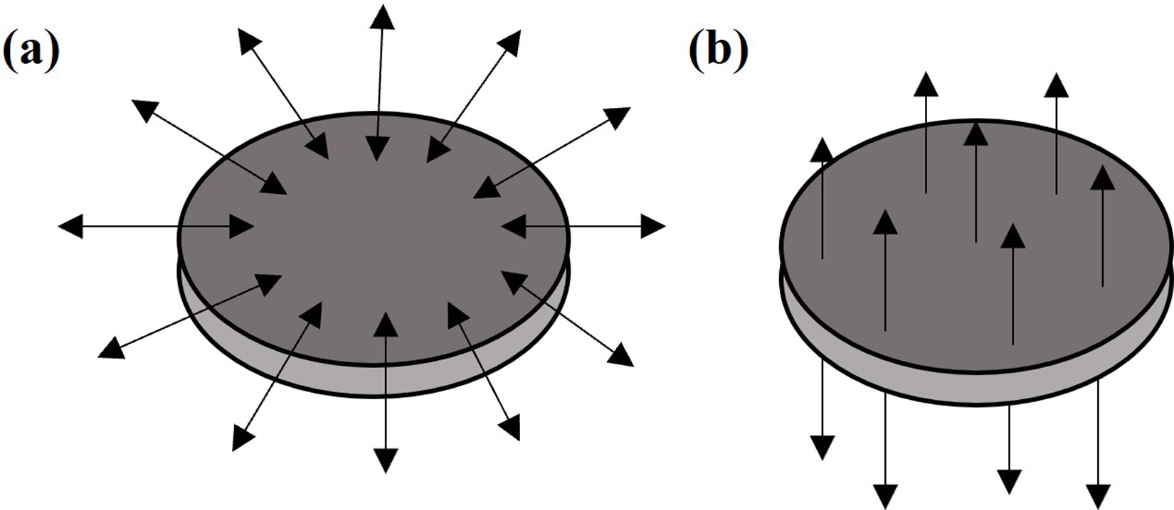
Radial (a) and through-thickness (b) polarization of piezoelectric discs. Arrows represent poling direction.
Several constants are used to define the induced electric field under different axes of applied mechanical load. Specifically, the piezoelectric voltage constant, g33, governs the voltage output in a through-thickness poled piezoelectric disc in compression. Including an interdigitated compliant layer (i.e., CLACS) increases lateral strain, invoking an additional voltage from the off-axis piezoelectric constant, g31, subsequently increasing overall power production (32). Finite element modeling of CLACS showed that the compliant layer expansion increased the piezoelectric radial strain more than the through-thickness strain (33).
In the present study, we investigate use of a new structural biomaterial which we call mixed-mode CLACS (MMCLACS). We hypothesize that poling direction of piezoelectric elements can be exploited to achieve enhanced power production from a composite piezoelectric stack. This solution enables effective energy harvesting from multiple loading directions, while maintaining necessary strength to be utilized as a structural material to generate electrical power from low frequency, physiologic mechanical loads experienced by orthopedic implants. The voltage generated from the piezoelectric material must be post-processed to deliver electronegative current densities within safe ranges (<2mA/cm2) to the healing site (34). Previous work from our group has defined a voltage threshold (50V peak-to-peak or 18V VRMS) necessary to power the circuitry and still produce sufficient electrical stimulation for bone healing (30).
The purpose of this study was to elucidate the effect of poling direction on power production of MMCLACS under simulated walking loads commonly experienced by orthopedic implants during fusion and fracture consolidation. Power generation of piezoelectric composite stacks with mixed poling directions under low frequency compressive and torsional loads has not previously been investigated. Combining radial and through-thickness piezoelectric elements within a stack is a novel configuration that we expected to provide interesting power producing capability in physiological torsion and compression.
Methods
Because traditional cofired stacks cannot vary poling direction of individual piezoelectric elements, CLACS fabrication methods were used in this study (29). In summary, commercially available, pre-poled piezoelectric discs were used to manufacture three MMCLACS groups as shown in Figure 2. To isolate the effect of poling direction, volume of piezoelectric material remained constant in each group. Radially poled stacks or R-CLACS are shown in Figure 2b, through-thickness poled stacks or T-CLACS are shown in Figure 2d and mixed mode or RT-CLACS with alternating radial and through-thickness poled elements are shown in Figure 2c. Power produced from each MMCLACS configuration was characterized over a range of dynamic compressive and torsional load amplitudes, low frequencies and electrical load resistances.
Figure 2.
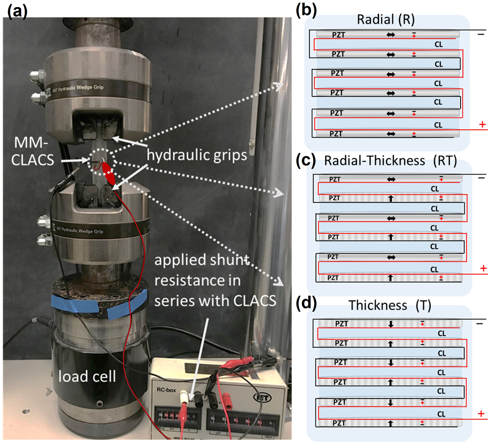
Experimental electromechanical setup and MMCLACS configurations.
(a). MMCLACS were electromechanically tested to compare voltage and power produced at varying low frequency, sinusoidal compressive and torsion load using a biaxial MTS MiniBionix 858 with hydraulic grips. Load was applied and voltage output was measured across a shunt resistance sweep in series with MMCLACS. (b). Schematic showing R-CLACS layup. (c). Schematic showing RT-CLACS layup. (d). Schematic showing T-CLACS layup. In b-d. arrows represent poling direction and positive/negative electrodes are labeled on each PZT disc. CL represents the compliant layers interdigitated between each PZT disc.
Material Considerations
Three configurations of MMCLACS, R-CLACS, RT-CLACS, and T-CLACS, were used to investigate the effect of poling direction on power generation. All MMCLACS groups utilized commercially available piezoelectric discs made with the same type of lead zirconate titanate (PZT), a PZT-5A Navy Type II (SM412, STEMiNC, Doral, FL). Discs were chosen to keep PZT type, size, and electrode type/size constant to isolate the effect of poling direction. This material was chosen based on the high electromechanical coupling coefficient (kt = 0.42) and the reasonable stiffness (Y33 = 56 GPa) for high load, low frequency applications. All discs were electroded and poled at the manufacturer. The electrodes were fired on silver and were applied to the top and bottom faces of the discs. The poling was completed under controlled conditions. According to STEMiNC, the radially poled discs (SMD10T02F412S) were poled on the radial direction, and the through-thickness discs (SMD10T02F412T) were poled axially as shown in Figure 1. To create the composite CLACS material, the epoxy used as the matrix material was a medical grade, room-temperature cure, two-part epoxy (EPO-TEK 301, Epoxy Technology, Billerica, MA). This material was chosen for its mechanical strength properties that are similar to common polymers used in orthopedic devices and desirable dielectric properties to decrease electric loss within the piezocomposite.
MMCLACS Fabrication
All MMCLACS were fabricated using the methods from a previously published CLACS study (29). In summary, the six PZT discs were connected electrically in parallel, stacked with interdigitated 0.4mm epoxy layers and encapsulated. The composite structures are shown in schematic form in Figure 2. The black and red lines represent the positive and negative electrical connections. Each type of MMCLACS (n=5 in each group) were composed of six PZT discs that were 10×0.2mm and five interdigitated compliant layers that were 0.4mm thick. Once stacked, each PZT-epoxy composite structure was a 10mm Ø x 3.2mm tall cylinder. The R-CLACS were made with six radially poled discs, and T-CLACS were made with six through-thickness poled discs. The RT-CLACS were made with three radially poled discs and three through-thickness poled discs, alternating radial and through-thickness (R and T).
The stacks were then encapsulated in EPO-TEK 11×45 mm cylinders (see Figure S1, Supplemental Material), ensuring the MMCLACS stacks were centered and aligned along the center axis of the cylinder. The cylindrical shape with tabs was designed to interface with the hydraulic grips used in testing, while maintaining an even stress distribution across the MMCLACS in compression and torsion. The volume of PZT (94 mm3), volume of epoxy, overall height and surface area was kept constant throughout all specimens. The electrical connection, impedance and capacitance was verified before each specimen was tested.
For the cofired stack analog comparison, stacks without compliant layers (R0, RT0, and T0) were manufactured (n=2 in each group). Six PZT discs were connected as explained above. A minimal amount of EPO-TEK 301 epoxy was used to adhere the discs together to create a uniform stack and ensure proper alignment once encapsulated.
Experimental Electromechanical Testing
For all electromechanical testing, a biaxial MTS MiniBionix 858 with 647 Hydraulic Wedge Grips was used to ensure consistency in testing across different loading conditions (MTS, Eden Prairie, MN). Tests were conducted in load-control utilizing a 25 kN, 250 N-m load cell. The gripping pressure used for all tests was 5 MPa, and was calculated based on specimen size and material from manufacturer recommendations. The MMCLACS voltage output was measured across an electrical load resistance (utilizing a decade box) and collected during each dynamic loading condition. The voltage, load and displacement data were all recorded utilizing the MTS DAQ system at a continuous sampling rate of 512 Hz.
The goal of this study is to understand the power generation efficiency of MMCLACS under physiological loads commonly seen in orthopedic implants, specifically spinal fusion implants and intramedullary rods that experience consistent dynamic loading during patient ambulation. In lumbar spinal fusion implants, the primary load experienced during walking is compression (35,36). The frequency range was chosen to represent walking, with 2Hz being the median value – 1Hz for each foot strike. Thus, to understand power generation capability of MMCLACS, voltage generation was measured as a function of pure compression loads (100–1000N) at a range of walking frequencies (1–5Hz). Intramedullary rods experience multi-axial loading during patient ambulation including compression and torsion. Torsional load estimates range from 2–8N-m at lower frequencies (0.5–3Hz) were utilized to simulate walking where the implant undergoes loading during each step with that leg (37,38). To simplify the application of results, power generation was measured under pure compressive loads and pure torsional loads separately. Conservative estimates for load amplitudes throughout the healing process were considered to develop loading conditions and characterize MMCLACS behavior across a range of inputs (35–38).
Compression Testing
A 1200N compressive preload was applied to ensure the specimen remained in compression throughout all loads tested. Cyclic compression at 100 N, 500 N, and 1000 N load amplitudes were applied at four low frequencies of 1 Hz, 2 Hz, 3 Hz and 5 Hz (see Figure S2, Supplemental Material). For each load and frequency, the voltage output was measured across a shunting resistance sweep of 20 kΩ−20 MΩ. Resistance values were chosen to characterize the behavior of MMCLACS at a range of resistances necessary for circuit design and to capture the resonance behavior at the matched impedance of the specimen. Voltage data for each load, frequency and resistance was collected for 15 cycles to capture steady-state behavior. A custom MATLAB (Mathworks, Natick, MA) code was used to filter the voltage data, remove the beginning and end cycles, and calculate the average maxima. The average voltage amplitude of the middle five cycles was converted to RMS (VRMS = Vamp/√2) and used for power calculations (P = VRMS2/R). Power for each loading condition was calculated (see Figure S3, Supplemental Material). Power output of each MMCLACS type as a function of poling direction was compared using a one-sided Wilcoxon Rank Sum test (α=.05).
Torsion Testing
To test the power production capability of each MMCLACS type in torsion, specimen were also electromechanically tested under pure torsional loads. A constant 200 N compressive preload was applied first to ensure the axial load on the MMCLACS remained constant throughout the remainder of the torsion loading cycles. Three torques, 2 N-m, 4 N-m, and 8 N-m, were applied at four frequencies 0.5 Hz, 1 Hz, 2 Hz, and 3 Hz (see Figure S6, Supplemental Material). Voltage output was measured across a shunt resistance sweep of 20 kΩ−20 MΩ, and power output was calculated as a function of applied torque, frequency and applied resistance. The same MATLAB code and calculations from the compression testing were used. Maximum power output of each MMCLACS type as a function of poling direction was compared using a one-sided Wilcoxon Rank Sum test (α=.05). The standard deviations in this test were high, so further statistical analysis and claims were not made.
Results
In order to assess the viability of MMCLACS as an energy harvesting biomaterial, the power generation capability across a range of loads, frequencies and resistances was characterized. The goal was to better understand power generation from simulated walking due to poling direction of the piezoelectric elements in the specimens tested. It is important to note that this exact design (volume of piezoelectric material, test specimen geometry, etc.) would not be appropriate for many implantable orthopedic devices, but the power generation trends of each type of MMCLACS under different loading conditions was compared and can be later applied to specific device design requirements.
Compressive Load Characterization
Figure 3 presents the average power generated by each MMCLACS group as a function of frequency at 1000N compressive load (Figure 3a) and as a function of load at 2Hz frequency (Figure 3b). These selected loading conditions best represent physiologic loading, but all data collected can be found in Supplemental Material Figure S4. At all loads and frequencies tested, RT-CLACS produced significantly more power than T-CLACS (p<.05). Across most loads and frequencies, RT-CLACS produced significantly more power than R-CLACS, and R-CLACS produced significantly more power than T-CLACS (p<.05). At the maximum load and frequency (1000 N, 5 Hz, 0.97 MΩ) RT-CLACS produced 818 µW, 27% more power than T-CLACS (646 µW). RT-CLACS produced 12% more than R-CLACS (730 µW). R-CLACS produced 13% more than T-CLACS. These statistical trends and percent increases in power were consistent for all loads, frequencies and resistances tested, demonstrating consistent increase in power due to RT-CLACS and R-CLACS, as compared to T-CLACS.
Figure 3.
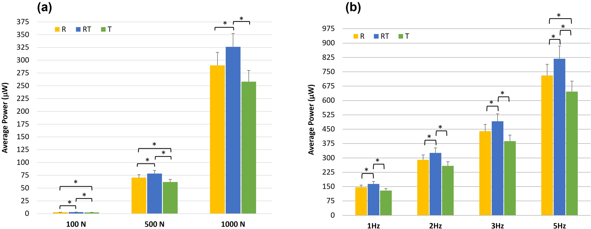
(a) Average power generated by each MMCLACS group as a function of applied compressive load at 2Hz. Power presented at resistance of maximum measured voltage - 2MΩ.
(b) Average power generated by each MMCLACS group as a function of frequency at 1000N compressive load. Power presented at resistance of maximum measured voltage at the resistance corresponding to maximum power for each frequency: 5MΩ at 1Hz, 2MΩ at 2Hz, 1.5MΩ at 3Hz, 0.97MΩ at 5Hz. Note: Error bars represent one standard deviation and *represents a significant difference (p<.05).
Because the MMCLACS layups and mixing of poling directions has not yet been characterized, the relationship between load and power generation at a given frequency was assessed. Increased compressive load amplitudes significantly increased power output for all groups (p<.05), following expected power generation behavior for piezoelectric generators. The relationship between power produced and applied mechanical compressive load is independent of frequency: a 112-fold increase from 100–1000 N, a 4-fold increase from 500–1000 N, and a 27-fold increase from 100–500 N. This linear relationship was consistent with all MMCLACS groups.
Similarly, the increased power due to increased frequency was characterized and found to increase linearly across all loads: 2-fold increase from 1–2 Hz, 3-fold increase from 1–3 Hz, and 5-fold increase from 1–5 Hz. Conventional piezoelectric stacks are composed of through-thickness poled elements like T-CLACS. Although unconventional, R-CLACS and RT-CLACS power generation behavior as a function of load and frequency followed the same percent increases as T-CLACS; percent increases were consistent across all MMCLACS. Data collected at all loads and frequencies with statistical trends are presented in full in the Supplemental Material.
When designing electrical stimulation devices, it is important to understand the behavior MMCLACS as a function of applied resistance, as that will define the integration with post-processing circuitry. To maximize power generation efficiency, one should try to match the circuit resistance to the resistance of maximum power (source impedance). Figure 4a shows power and voltage produced as a function of resistance and poling direction at 1000 N and 2 Hz. The available voltage is plotted with the calculated power across the sweep of resistances on a semi-log scale for clarity. Poling direction of the PZT did not affect the resistance at which maximum power occurred. At 2 Hz, the source impedance for all groups was 2.5 MΩ. Additionally, the voltage output for all three groups of MMCLACS was at this loading condition was above the threshold of 17V at all resistances above 1.5MΩ. The power and voltage curves for all loads and frequencies are presented in the Supplemental Material in Figure S5.
Figure 4.
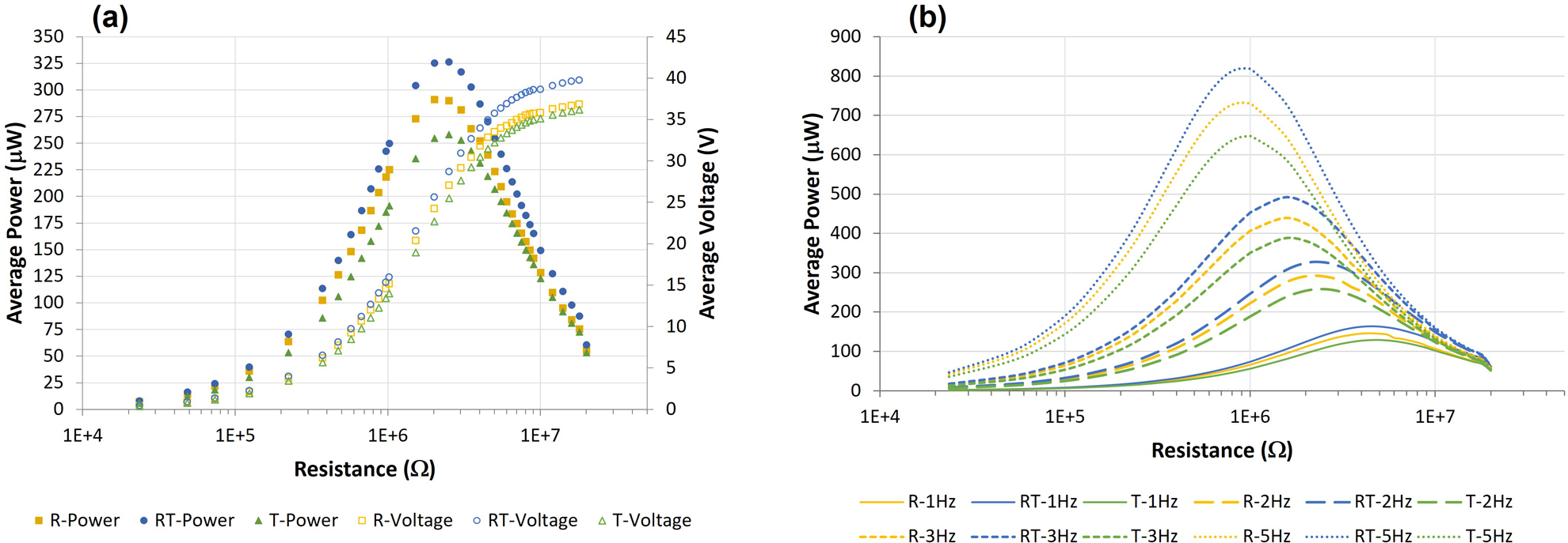
(a) Average power and voltage output for each MMCLACS group as a function of poling direction and resistance applied at 1000N and 2Hz. Note the resistance is plotted on a log scale for clarity. (b) Average power generation curves as a function of resistance for each MMCLACS group presented at each frequency tested at 1000N. This demonstrates the effect of frequency on power generated and resistance of maximum power generation, or optimal resistance. Error bars left off for clarity.
RT-CLACS produced more power than both other groups across all resistances tested, and R-CLACS produced more than T-CLACS. The influence of frequency on the resistance at which maximum power is produced is shown in Figure 4b. Although alternating poling direction significantly increased power generation, it was not due to a change in impedance; all three groups exhibited the same experimental source impedances across all frequencies. As frequency increased, power increased and impedance decreased, as shown by maximum power occurring at lower resistances. The optimal resistances for all groups were as follows: 5 MΩ at 1 Hz, 2.5 MΩ at 2 Hz, 1.5 MΩ at 3 Hz, 0.97 MΩ at 5 Hz. The significant increase in power output of RT-CLACS validates use as an efficient energy harvester at all resistances and frequencies far below PZT resonance, and the presented data gives design inputs for post-processing circuitry considerations.
Figure 5 presents average voltage as a function of frequency and load for each group at several different resistances. The voltage is the VRMS at each loading condition which represents the available voltage produced from the piezoelectric generator at the load/frequency presented. At 10 MΩ, RT-CLACS produced on average 3V more than R-CLACS and T-CLACS, which produced approximately the same voltage. At 1 MΩ, voltage increased by approximately 1–1.5 V from T-CLACS to R-CLACS to RT-CLACS across all four frequencies. At low resistances the differences were less between the three groups, suggesting that RT-CLACS most effectively increase voltage at higher resistances.
Figure 5.
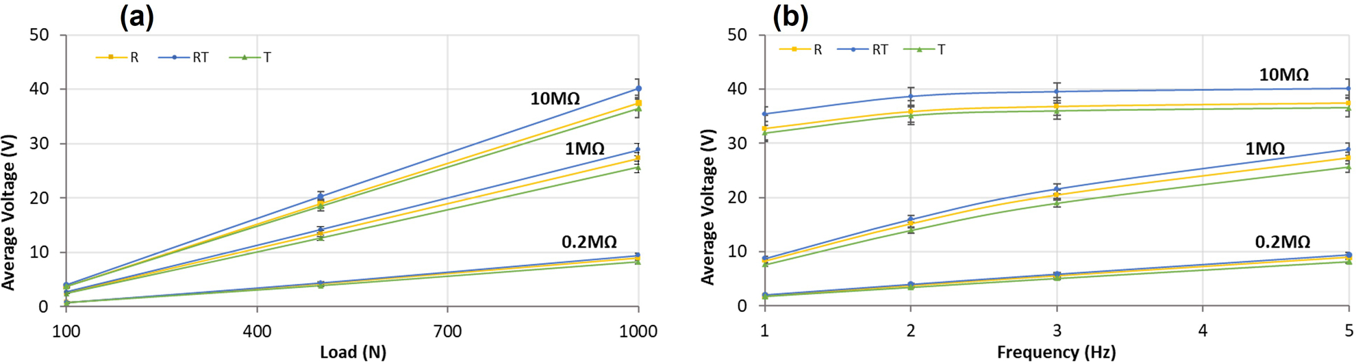
(a). Average voltage generated from each MMCLACS group as a function of load applied (b). Average voltage generated from each MMCLACS group as a function of frequency applied. Note: voltage is the VRMS equivalent calculated from the average amplitude of the AC voltage signal collected at each load, frequency and resistance. Error bars represent one standard deviation.
This is an initial characterization of a novel piezoelectric material, thus direct comparisons to other piezoelectric generators can be difficult due to differences in material properties and testing conditions. However, power density is a measure of efficiency for energy harvesting and can be used when designing future implants with given power requirements and geometric design inputs for the MMCLACS stacks. Power density as a function of poling direction and load applied demonstrate the efficiency of RT-CLACS (Figure 6a). Power density was calculated as a function of the PZT volume (94 mm3), which was constant for all groups. The increase in power density was consistent for all loads, frequencies, and resistances tested. Figure 6b shows power density as a function of frequency. Results are presented at the resistance of maximum power for each frequency. The simulated walking load of 1000 N and 2 Hz, RT-CLACS produced 3.5 µW/mm3, R-CLACS produced 3.1 µW/mm3, and T-CLACS produced 2.7 µW/mm3. Assuming implants have an available volume to incorporate MMCLACS within of ~75–100 mm3, and associated circuitry has a resistance ~30 MΩ, these power densities are an order of magnitude higher than necessary to produce 18 VRMS of voltage to power the circuit and deliver DC current to stimulate bone growth.
Figure 6.
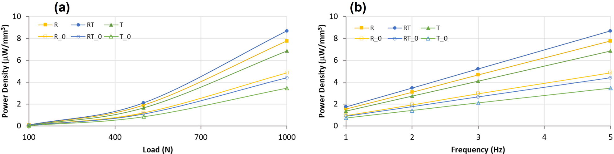
(a) Average power density for each MMCLACS group as a function of load applied. Data presented for 5Hz frequency and resistance of maximum power, 0.97MΩ. (b). Average power density for each MMCLACS group as a function of frequency applied. Power data is presented at 1000N and the the resistance of maximum power for each frequency: 5MΩ at 1Hz, 2.5MΩ at 2Hz, 1.5MΩ at 3Hz, 0.97MΩ at 5Hz. Error bars left off for clarity.
Stacks without compliant layers (R0, RT0, T0 in Figure 6) were made to validate the CLACS effect paired with the effect of poling direction (see Methods). CLACS substantially increased power density, as found previously: T-CLACS power density is approximately double T0 power density. Power increase due to compliant layer interdigitation in T-CLACS is consistent with previous work on CLACS (29,31,39). RT-CLACS increased power density by 100%, and R-CLACS increased power density by approximately 60%, as compared to RT0 and R0 stacks respectively. Comparing the effect of poling direction within a stack without compliant layers, it should be noted that R0 stacks generated slightly higher power densities than RT0 stacks, and both R0 and RT0 stacks generated more power than T0 stacks. These results suggest that radially poled piezoelectric elements within a cofired stack could be an effective way to increase efficiency, without the additional space requirements to create the CLACS structure.
We note that the MMCLACS configurations presented are conceptual constructions that are not yet optimized to achieve maximum overall combined power generation from addition of compliant layers and mixed poling directions. While these opportunities for further optimization of device geometry and properties are worth highlighting and are currently the subject of additional investigation, we focus here on further experimental demonstration of power generation capabilities of these three MMCLACS groups.
Torsional Load Characterization
MMCLACS were designed to be a versatile energy harvesting structural material for use in implants experiencing multiaxial loading (e.g. fracture fixation rods/plates). To further characterize MMCLACS, power generated from low frequency torsional loads was also evaluated (Supplemental Material, Table S1 and Figures S6-S8). These results provide a basis for analyzing viability of MMCLACS power generation from off-axis loading. To inform future design of implants, especially intramedullary rods, power generation under pure torsional loads was characterized. For all MMCLACS configurations tested, the power and voltage generated was below the threshold 18 VRMS/150 µW as defined in the introduction. In order to characterize MMCLACS ability to power the post processing circuitry and deliver electrical stimulation, these thresholds were used to assess energy harvesting capability under torsional loads. However, other devices and applications need less power and thus a summary of power produced under the selected physiological torsional loads is presented.
At all torques and frequencies, R-CLACS and T-CLACS produced significantly more power than RT-CLACS (p<.05), producing 1.14 ± 0.55 µW and 1.35 ± 0.54 µW respectively at maximum power (8 N-m, 3 Hz, 1.6 MΩ). RT-CLACS produced approximately 70% less (0.36 ± 0.29 µW) at the same torque and frequency. Maximum power occurred at the same resistance for all MMCLACS groups and increasing frequency decreased source impedance as expected: 12 MΩ at 0.5 Hz, 5.6 MΩ at 1 Hz, 2.6 MΩ at 2 Hz, and 2.1 MΩ at 3 Hz.
Power output increased with increasing torque and frequency consistently for all groups; 4.3-fold increase from 2–4 N-m and 4–8 N-m, and 19-fold increase from 2–8 N-m. Similar to behavior under compression, as frequency increased power production increased uniformly independent of load and resistance: from 0.5–1 Hz and 1–2 Hz the power doubled, from 2–3 Hz there was a 1.5-fold increase, and from 1–3 Hz there was a 3-fold increase.
R0, RT0, and T0 stacks were also tested in torsion. R0 and RT0 stacks produced approximately 4 times more power than R-CLACS and RT-CLACS. In contrast, T0 and T-CLACS produced approximately the same amount of power. R0, RT0, and T0 stacks followed the same impedance trends as the R-CLACS, RT-CLACS and T-CLACS. These findings suggest that a radially poled PZT cofired stack (R0) would be most efficient for power generation under pure torsional loads.
To the best of our knowledge power generation capability of piezocomposite stacks from torsion has not been previously investigated. Power generated from MMCLACS at tested torques was a fraction of that generated from compression and may not be enough power for some applications. However, when smaller amounts of power are necessary (i.e. micro/nano generators) utilizing MMCLACS may be a viable option to harvest energy from torsional loads and generate power in the nanowatt range.
Discussion
Technological Perspective and Clinical Outlook
Translation of MMCLACS could address two technical issues in practical and clinical applications of piezoceramic stack energy harvesting – poor low frequency power generation efficiency and low fatigue performance. If piezoceramic stacks could be toughened to withstand multiaxial loads experienced in vivo, they could act as an effective generator within an implant to provide DC electrical stimulation directly to a fracture or fusion site, capitalizing on bone healing electrical stimulation while eliminating the need for a battery. Utilizing the piezoelectric effect of the PZT generator, the motion of the patient would dynamically load the implant, subsequently producing electrical stimulation in sync with the mechanical load, mimicking the body’s natural bone regeneration process (40). As demonstrated in a preclinical pilot study, this type of piezoelectric implant providing pulsed DC stimulation allowed for faster, more robust fusion (20). Although not the same PZT volume and vastly different composite configurations, under the same simulated walking loading conditions, all MMCLACS produced sufficient power to stimulate healing at lower resistances as described in previous work (18,19,29).
All piezoelectric energy harvesters generate alternating current (AC) signals, thus require circuits for signal conditioning and/or rectification. Bone growth is stimulated by negative DC (41), thus design of a piezoelectric biomaterial to supply this stimulation requires a rectifying circuit to change the AC to DC, condition and subsequently deliver the negative current to the desired bone healing site. Several rectification components require higher voltage outputs than most piezoelectric generators produce under low frequency loads (42). The threshold voltage requirements and expected loss during rectification limit circuit design. MMCLACS produce significantly higher voltages at lower frequencies and resistances than standard piezoelectric energy harvesters, overcoming these rectification issues, increasing circuit design options and potential for miniaturization for use in MEMS and/or integration into current implant designs. In addition, the composite material provides toughness where brittle, cofired stacks would not be appropriate. CLACS have better fatigue resistance than cofired stacks (30). This allows MMCLACS to be incorporated as a load-bearing material within existing structures, broadening potential use in devices that require fatigue-resistant energy harvesting (i.e. medical implants, sidewalks/roadways, shoes, etc.).
The PZT discs used here in T-CLACS were soft PZT, while the PZT discs used in the initial CLACS study were hard PZT (29). The increase in power output due to compliant layers that were twice PZT disc thickness was consistent across both studies: approximately 60% increase in CLACS and approximately 100% increase in the T-CLACS in this study. This suggests that the effect of interdigitated compliant layers within a soft PZT stack further enhances power generation. Soft PZT has also been shown to be more efficient at off-resonance, lower frequencies in other energy harvesting applications (43). The unique MMCLACS fabrication technique allows pre-poled PZT discs to be combined into one uniform mechanical structure, coupling the effect of poling direction and CLACS. R-CLACS increased power production by 125% as compared to T0 stacks, an additional 25% due to radially poled discs. Alternating R and T discs to create RT-CLACS, increased power output by a total of 250%, as compared to T0 stacks (cofired stack analog). This compelling result presents opportunities for all MMCLACS to be utilized as a structural energy harvesting material to generate usable power from common human and other low frequency cyclic motion.
This characterization of MMCLACS exemplifies the versatility of CLACS technology to generate power more efficiently at low frequencies seen in implantable medical devices, wearables, civil infrastructure and a variety of self-powered devices. Reported peak power densities for piezoelectric materials range from 50 µW/cm3 to 2700 µW/cm3 from a variety of loading conditions (44–47). Several of these devices are beams, requiring high frequency excitation vibrations (> 100 Hz) and space for maximum beam deflection. It is difficult to make direct comparisons with other devices due to vast differences in material, loads applied and device structure. However, it is notable that at 1000 N and the exceptionally low, off-resonance frequency of 5 Hz, RT-CLACS, R-CLACS, and T-CLACS in this study produced 8700 µW/cm3, 7800 µW/cm3, and 6900 µW/cm3 respectively, over 2.5 times more power per volume of PZT due to the unique MMCLACS structure.
The main motivation of this work is to characterize the power production of MMCLACS for use as a robust piezoelectric biomaterial that could be incorporated into existing implants to provide bone healing electrical stimulation without the use of a battery. However, with the increase in power production efficiency of the RT-CLACS and R-CLACS, it is possible that this material could also act as a load sensing mechanism to track bone healing union progression. The issues associated with assessing union and fracture healing progression have attributed to the high rates of nonunions developed in orthopedic procedures (48). As bone grows in and around implants, load on the implant is reduced (38). As demonstrated in this work, as the dynamic loads decreased, MMCLACS power production also decreases. The load-power relationship developed (Figure 3) would relate the decrease in load experienced by the implant and predict the level of fusion/fracture consolidation. Recently, there has been work to assess fracture healing progression through external fixators (49), but incorporating this sensing technology into fusion and fracture fixation devices has not been done. The ability to determine fusion and/or union from sensor data would eliminate issues with expensive, qualitative healing assessment, potentially decreasing nonunion rates (50,51).
MMCLACS capitalize on expansion of the compliant layer and induce charge generation from several piezoelectric properties not possible in a traditional cofired stack generator, subsequently harvesting energy from multi-axial loads, not just pure compression (32). The poling direction in relation to the applied load direction, is an important factor that influences power production of piezoelectric energy harvesters. Under compressive loading, an axial through-thickness poling direction is the industry standard because when the poling direction and loading axis are parallel, the highest piezoelectric constant dictates the power generation. Although not yet completely understood, some piezoelectric models predict a coupling between radial and longitudinal partial systems at certain aspect ratios, and infer that an angled poling direction could activate an electric field from all three piezoelectric constants simultaneously (52,53). Once the dipoles within the piezoelectric material are aligned or poled, the material is anisotropic, thus several piezoelectric material properties are defined to describe the electric fields generated under different types of mechanical loading (e.g. compression, shear, etc.). Industry standard cofired stacks only generate power from one piezoelectric constant because the strain on the material is aligned with the uniform poling direction. However, RT-CLACS with mixed poling directions likely generates power from mechanical strain in multiple axes. Looking at RT-CLACS as a uniform structure, the ‘composite poling direction’ would be at an angle, invoking voltage generation from all three modes, and could explain the increase in power generation found in this study.
In this work, we strategically explored the impact of poling direction on power generation. Although this work was focused on initial characterization, further work should explore ability of MMCLACS to produce power from cyclic tensile loads, something that is not possible for traditional piezoceramic energy harvesting devices. Further work characterizing and defining relationships of PZT disc/compliant layer aspect ratio and stiffness could generate an ideal composition for desired applications. It is likely that a specific compliant layer material and thickness would optimize power generation of MMCLACS and should be further explored. The RT-CLACS structure in this work represents one possible configuration of alternating poling directions, but several other approaches can be imagined, capitalizing on disc position within the stack and incorporating overall device structure into design decisions. An elaborate finite element analysis of both conventional CLACS and MMCLACS is of great interest, is under way, and left for further investigation. Additionally, the mechanical properties and fatigue resistance of MMCLACS should be assessed to further validate use as a robust, load-bearing biomaterial.
Conclusion
A new class of energy harvesters, MMCLACS, has been proposed and initially investigated as a piezoelectric orthopedic implant material that would provide electrical stimulation to aid in bone healing. This structural biomaterial shows the impact of poling direction on power generation in a piezoelectric composite stack. The functional performance of these devices under compressive and torsional low frequency loads was validated. RT-CLACS generate more power than both R-CLACS and T-CLACS under compressive loads with power densities of 3500 µW/cm3, 3100 µW/cm3, 2700 µW/cm3 respectively, at simulated walking loads. Torsional loads produced limited power, but design would need to be optimized for use in most applications. MMCLACS produce more power than traditional piezoelectric stack generators under compressive loads. This additional increase in power could aid in the design of implants in which higher power densities are needed due to larger electrode surface areas or lower load amplitudes or frequencies. Because minimal power was produced in torsion, implants should be designed to apply purely dynamic compressive loads on the piezocomposite insert of the implant in order to generate sufficient power for electrical stimulation. Additionally, MMCLACS could be incorporated within implants as sensors to provide quantitative measures of the progression of fracture and fusion healing. Because of the higher power densities generated from RT-CLACS under moderate compressive loads, the wide and varied use of this technology could greatly increase efficiency of power generation from human motion, roadways, wearables, wind energy, etc. The ability to overcome efficiency losses due to frequency mismatches provides a promising route for further exploration and a practical material for energy harvesting implementation utilizing existing devices and technology.
Supplementary Material
Acknowledgements
This work was supported by NIH R41 AR070088. The authors also thank Madison and Lila Self Graduate Fellowship for generous support of graduate research at The University of Kansas.
Contributor Information
Ember Krech, Bioengineering Graduate Program, University of Kansas, Lawrence, KS, 66049, USA.
Evan Haas, Department of Mechanical Engineering, University of Kansas, Lawrence, KS, 66049, USA.
Grace Tideman, Department of Mechanical Engineering, University of Kansas, Lawrence, KS, 66049, USA.
Bonnie Reinsch, Department of Chemical Engineering, University of Kansas, Lawrence, KS, 66049, USA.
Elizabeth Friis, Bioengineering Graduate Program, University of Kansas, Lawrence, KS, 66049, USA, Department of Mechanical Engineering, University of Kansas, Lawrence, KS, 66049, USA.
References
- 1.Ekegren CL, Edwards ER, de Steiger R, Gabbe BJ. Incidence, Costs and Predictors of Non-Union, Delayed Union and Mal-Union Following Long Bone Fracture. Int J Environ Res Public Health 2018. 13;15(12). [DOI] [PMC free article] [PubMed] [Google Scholar]
- 2.Reid JJ, Johnson JS, Wang JC. Challenges to bone formation in spinal fusion. J Biomech 2011. Jan 11;44(2):213–20. [DOI] [PubMed] [Google Scholar]
- 3.Gebauer D, Mayr E, Orthner E, Ryaby JP. Low-intensity pulsed ultrasound: effects on nonunions. Ultrasound Med Biol 2005. Oct;31(10):1391–402. [DOI] [PubMed] [Google Scholar]
- 4.Leighton R, Watson JT, Giannoudis P, Papakostidis C, Harrison A, Steen RG. Healing of fracture nonunions treated with low-intensity pulsed ultrasound (LIPUS): A systematic review and meta-analysis. Injury 2017. Jul;48(7):1339–47. [DOI] [PubMed] [Google Scholar]
- 5.Heckman JD, Sarasohn-Kahn J. The economics of treating tibia fractures. The cost of delayed unions. Bull Hosp Jt Dis N Y N 1997;56(1):63–72. [PubMed] [Google Scholar]
- 6.Aleem IS, Aleem I, Evaniew N, Busse JW, Yaszemski M, Agarwal A, et al. Efficacy of Electrical Stimulators for Bone Healing: A Meta-Analysis of Randomized Sham-Controlled Trials. Sci Rep [Internet] 2016. Aug 19;6. Available from: https://www.ncbi.nlm.nih.gov/pmc/articles/PMC4990885/ [DOI] [PMC free article] [PubMed] [Google Scholar]
- 7.Brighton CT, Shaman P, Heppenstall RB, Esterhai JL, Pollack SR, Friedenberg ZB. Tibial nonunion treated with direct current, capacitive coupling, or bone graft. Clin Orthop 1995. Dec;(321):223–34. [PubMed] [Google Scholar]
- 8.Cottrill E, Pennington Z, Ahmed AK, Lubelski D, Goodwin ML, Perdomo-Pantoja A, et al. The effect of electrical stimulation therapies on spinal fusion: a cross-disciplinary systematic review and meta-analysis of the preclinical and clinical data. J Neurosurg Spine 2019. Oct 8;1–21. [DOI] [PubMed]
- 9.Kahanovitz N The Use of Adjunctive Electrical Stimulation to Enhance the Healing of Spine Fusions: Spine 1996. Nov;21(21):2523–5. [DOI] [PubMed] [Google Scholar]
- 10.Kucharzyk DW. A controlled prospective outcome study of implantable electrical stimulation with spinal instrumentation in a high-risk spinal fusion population. Spine 1999. Mar 1;24(5):465–8; discussion 469. [DOI] [PubMed] [Google Scholar]
- 11.Toth JM, Seim HB, Schwardt JD, Humphrey WB, Wallskog JA, Turner AS. Direct current electrical stimulation increases the fusion rate of spinal fusion cages. Spine 2000. Oct 15;25(20):2580–7. [DOI] [PubMed] [Google Scholar]
- 12.Meril AJ. Direct current stimulation of allograft in anterior and posterior lumbar interbody fusions. Spine 1994. Nov 1;19(21):2393–8. [DOI] [PubMed] [Google Scholar]
- 13.Rogozinski A, Rogozinski C. Efficacy of implanted bone growth stimulation in instrumented lumbosacral spinal fusion. Spine 1996. Nov 1;21(21):2479–83. [DOI] [PubMed] [Google Scholar]
- 14.Evans RD, Foltz D, Foltz K. Electrical stimulation with bone and wound healing. Clin Podiatr Med Surg 2001. Jan;18(1):79–95, vi. [PubMed] [Google Scholar]
- 15.Haddad JB, Obolensky AG, Shinnick P. The Biologic Effects and the Therapeutic Mechanism of Action of Electric and Electromagnetic Field Stimulation on Bone and Cartilage: New Findings and a Review of Earlier Work. J Altern Complement Med 2007. Jun;13(5):485–90. [DOI] [PubMed] [Google Scholar]
- 16.Rajabi AH, Jaffe M, Arinzeh TL. Piezoelectric materials for tissue regeneration: A review. Acta Biomater 2015. Sep 15;24:12–23. [DOI] [PubMed] [Google Scholar]
- 17.Anton SR, Sodano HA. A review of power harvesting using piezoelectric materials (2003–2006). Smart Mater Struct 2007;16(3):R1. [Google Scholar]
- 18.Goetzinger NC, Tobaben EJ, Domann JP, Arnold PM, Friis EA. Composite piezoelectric spinal fusion implant: Effects of stacked generators. J Biomed Mater Res B Appl Biomater 2016. Jan 1;104(1):158–64. [DOI] [PubMed] [Google Scholar]
- 19.Tobaben EJ, Goetzinger NC, Domann JP, Barrett-Gonzalez R, Arnold PM, Friis EA. Stacked macro fiber piezoelectric composite generator for a spinal fusion implant. Smart Mater Struct 2015;24(1):017002. [Google Scholar]
- 20.Friis E, Galvis S, Arnold P. DC Stimulation for Spinal Fusion with a Piezoelectric Composite Material Interbody Implant: An Ovine Pilot Study [Internet] Poster presented at: Society for Biomaterials 2015 Annual Meeting; 2015. Apr 15; Charlotte, NC. Available from: http://abstracts.biomaterials.org/data/papers/2015/abstracts/809.pdf [Google Scholar]
- 21.Li H, Tian C, Deng ZD. Energy harvesting from low frequency applications using piezoelectric materials. Appl Phys Rev 2014. Nov 6;1(4):041301. [Google Scholar]
- 22.Mitrovic M, Carman G P, Straub F K. Response of piezoelectric stack actuators under combined electro-mechanical loading. Int J Solids Struct 2001. Jun 1;38(24):4357–74. [Google Scholar]
- 23.Pritchard J, Bowen C, Lowrie F. Multilayer Actuators: Review. Br Ceram Trans 2001. Jun 1;100:265–73. [Google Scholar]
- 24.Xu TB, Siochi EJ, Kang JH, Zuo L, Zhou W, Tang X, et al. Energy harvesting using a PZT ceramic multilayer stack. Smart Mater Struct 2013;22(6):065015. [Google Scholar]
- 25.Feenstra J, Granstrom J, Sodano H. Energy harvesting through a backpack employing a mechanically amplified piezoelectric stack. Mech Syst Signal Process 2008. Apr 1;22(3):721–34. [Google Scholar]
- 26.Zhao S, Erturk A. Deterministic and band-limited stochastic energy harvesting from uniaxial excitation of a multilayer piezoelectric stack. Sens Actuators Phys 2014. Aug 1;214:58–65. [Google Scholar]
- 27.Platt SR, Farritor S, Garvin K, Haider H. The use of piezoelectric ceramics for electric power generation within orthopedic implants. IEEEASME Trans Mechatron 2005. Aug;10(4):455–61. [Google Scholar]
- 28.Platt SR, Farritor S, Haider H. On low-frequency electric power generation with PZT ceramics. IEEEASME Trans Mechatron 2005. Apr;10(2):240–52. [Google Scholar]
- 29.Krech ED, Cadel ES, Barrett RM, Friis EA. Effect of compliant layers within piezoelectric composites on power generation providing electrical stimulation in low frequency applications. J Mech Behav Biomed Mater [Internet] 2018. Aug 21 [cited 2018 Aug 31]; Available from: http://www.sciencedirect.com/science/article/pii/S1751616118309895 [DOI] [PMC free article] [PubMed]
- 30.Krech ED, LaPierre LJ, Tuncdemir S, Gurdal AE, Haas EG, Arnold PM, et al. Design considerations for piezoelectrically powered electrical stimulation: The balance between power generation and fatigue resistance. J Mech Behav Biomed Mater 2022. Feb 1;126:104976. [DOI] [PMC free article] [PubMed] [Google Scholar]
- 31.Cadel ES, Krech ED, Arnold PM, Friis EA. Stacked PZT Discs Generate Necessary Power for Bone Healing through Electrical Stimulation in a Composite Spinal Fusion Implant. Bioeng Basel Switz 2018. Oct 23;5(4). [DOI] [PMC free article] [PubMed] [Google Scholar]
- 32.Krech ED, Barrett RM, Cadel ES, Friis EA. Power Generation Amplification and Stack Toughening via Compliant Layer Interdigitation 2018;(51951):V002T07A010.
- 33.Cadel ES, Frazer LL, Krech ED, Fischer KJ, Friis EA. Analysis of how compliant layers and encapsulation affect power generated from piezoelectric stacked composites for bone healing medical devices. J Biomed Mater Res A 2019;107(12):2610–8. [DOI] [PubMed] [Google Scholar]
- 34.Isaacson BM, Bloebaum RD. Bone bioelectricity: what have we learned in the past 160 years? J Biomed Mater Res A 2010. Dec 15;95(4):1270–9. [DOI] [PubMed] [Google Scholar]
- 35.Arshad R, Angelini L, Zander T, Di Puccio F, El-Rich M, Schmidt H. Spinal loads and trunk muscles forces during level walking – A combined in vivo and in silico study on six subjects. J Biomech [Internet] 2017. Aug 26; Available from: http://www.sciencedirect.com/science/article/pii/S0021929017304323 [DOI] [PubMed]
- 36.Rohlmann A, Bergmann G, Graichen F. Loads on an internal spinal fixation device during walking. J Biomech 1997. Jan 1;30(1):41–7. [DOI] [PubMed] [Google Scholar]
- 37.Duda GN, Schneider E, Chao EYS. Internal forces and moments in the femur during walking. J Biomech 1997. Sep 1;30(9):933–41. [DOI] [PubMed] [Google Scholar]
- 38.Schneider E, Michel MC, Genge M, Zuber K, Ganz R, Perren SM. Loads acting in an intramedullary nail during fracture healing in the human femur. J Biomech 2001. Jul;34(7):849–57. [DOI] [PubMed] [Google Scholar]
- 39.Pessia ZR, Cunningham CA, Krech ED, Friis EA. Power amplification via compliant layer interdigitation and dielectrophoretic structuring of PZT particle composites. Smart Mater Struct [Internet] 2020. [cited 2020 Apr 30]; Available from: 10.1088/1361-665X/ab85a5 [DOI]
- 40.Ahn AC, Grodzinsky AJ. Relevance of collagen piezoelectricity to “Wolff’s Law”: a critical review. Med Eng Phys 2009. Sep;31(7):733–41. [DOI] [PMC free article] [PubMed] [Google Scholar]
- 41.Gittens RA, Olivares-Navarrete R, Rettew R, Butera RJ, Alamgir FM, Boyan BD, et al. Electrical Polarization of Titanium Surfaces for the Enhancement of Osteoblast Differentiation. Bioelectromagnetics 2013. Dec;34(8):599–612. [DOI] [PMC free article] [PubMed] [Google Scholar]
- 42.Kim SB, Park H, Kim SH, Wikle HC, Park JH, Kim DJ. Comparison of MEMS PZT Cantilevers Based on 31 and 33 Modes for Vibration Energy Harvesting. J Microelectromechanical Syst 2013. Feb;22(1):26–33. [Google Scholar]
- 43.Shahab S, Zhao S, Erturk A. Soft and Hard Piezoelectric Ceramics and Single Crystals for Random Vibration Energy Harvesting. Energy Technol 2018;6(5):935–42. [Google Scholar]
- 44.Ali SF, Friswell MI, Adhikari S. Analysis of energy harvesters for highway bridges. J Intell Mater Syst Struct 2011. Nov 1;22(16):1929–38. [Google Scholar]
- 45.El-hami M, Glynne-Jones P, White NM, Hill M, Beeby S, James E, et al. Design and fabrication of a new vibration-based electromechanical power generator. Sens Actuators Phys 2001. Aug 1;92(1):335–42. [Google Scholar]
- 46.Roundy S, Leland ES, Baker J, Carleton E, Reilly E, Lai E, et al. Improving power output for vibration-based energy scavengers. IEEE Pervasive Comput 2005. Jan;4(1):28–36. [Google Scholar]
- 47.Shen D, Park JH, Noh JH, Choe SY, Kim SH, Wikle HC, et al. Micromachined PZT cantilever based on SOI structure for low frequency vibration energy harvesting. Sens Actuators Phys 2009. Aug 31;154(1):103–8. [Google Scholar]
- 48.Morshed S Current Options for Determining Fracture Union. Adv Med 2014;2014:708574. [DOI] [PMC free article] [PubMed] [Google Scholar]
- 49.Ong WH, Chiu WK, Russ M, Chiu ZK. Integrating sensing elements on external fixators for healing assessment of fractured femur. Struct Control Health Monit 2016;23(12):1388–404. [Google Scholar]
- 50.Papi E, Koh WS, McGregor AH. Wearable technology for spine movement assessment: A systematic review. J Biomech 2017. July;64:186–97. [DOI] [PMC free article] [PubMed] [Google Scholar]
- 51.van Bilsen MWT, Ullrich C, Ferraris L, Hempfing A, Hitzl W, Mayer M, et al. Diagnostic accuracy of CT scan-based criteria compared with surgical exploration for the analysis of cervical fusion and nonunion. J Neurosurg Spine 2020. Mar 6;1–7. [DOI] [PubMed]
- 52.Kiran R, Kumar A, Kumar R, Vaish R. Poling direction driven large enhancement in piezoelectric performance. Scr Mater 2018. Jul 1;151:76–81. [Google Scholar]
- 53.Xu J, Lin S, Ma Y, Tang Y. Analysis on Coupled Vibration of a Radially Polarized Piezoelectric Cylindrical Transducer. Sensors 2017. Dec;17(12):2850. [DOI] [PMC free article] [PubMed] [Google Scholar]
Associated Data
This section collects any data citations, data availability statements, or supplementary materials included in this article.