

Abstract
Implementation of a high-frequency ultrasound (HFUS) beamformer is computationally challenging because of its high sampling rate. This article introduces an efficient beamformer with sub-Nyquist sampling (or bandpass sampling) that is suitable for HFUS imaging. Our approach used channel radio frequency data sampled at bandpass sampling rate (i.e., ) and postfiltering-based interpolation to reduce the computational complexity. A polyphase structure for interpolation was used to further reduce the computational burden while maintaining an adequate delay resolution . The performance of the proposed beamformer (i.e., sampling with sixfold interpolation, ) was compared with that of the conventional method (i.e., sampling with fourfold interpolation, ). Ultrafast coherent compounding imaging was used in simulation, in vitro and in vivo imaging experiments. Axial/lateral resolution and contrast-to-noise ratio (CNR) values were measured for quantitative evaluation. The number of transmit pulse cycles was varied from 1 to 3 using two transducers with different fractional bandwidths ( and . In the simulation, the proposed and conventional methods showed the similar axial beam widths (63.5 and , respectively) from the two-cycle transmit pulse using the transducer with a bandwidth of . In vitro and in vivo imaging experiments were performed using a Verasonics ultrasound research platform equipped with a high-frequency array transducer (20–46 MHz). The in vitro imaging results using a wire target showed consistent results with the simulation study (i.e., disparity at −6-dB axial resolution). The in vivo feasibility study with a murine mouse model with breast cancer was also performed, and the proposed method yielded a similar image quality compared with the conventional method. From these studies, it was demonstrated that the proposed HFUS beamformer based on the bandpass sampling can substantially reduce the computational complexity while minimizing the loss of spatial resolution for HFUS imaging.
Keywords: Bandpass sampling, computational complexity, high-frequency ultrasound (HFUS), postfiltering-based beamformer
I. Introduction
HIGH-FREQUENCY ultrasound (HFUS) imaging has been applied to various pre-clinical and clinical applications, including biomicroscopy, intravascular imaging, and small animal imaging because of its submillimeter-scale spatial resolution [1]–[3]. Implementation of HFUS imaging was typically done with a single-element transducer scanned by a mechanical stage, which is practical and cost-effective [4]–[6]. However, the fixed focus of a single-element transducer and the low frame rate because of mechanical scanning limit the spatial and temporal resolutions of HFUS imaging [7], [8].
Adoption of dynamic receive beamformers (DRBFs) in HFUS imaging improves the signal-to-noise ratio (SNR) and spatial resolution significantly [7]–[11]. However, DRBFs for HFUS imaging require increased hardware complexity and memory size. For example, the center frequency of needs analog-to-digital converters (ADCs) operated at when the sampling rule is applied. Thus, real-time portable HFUS imaging systems are still challenging to implement. In addition, interpolators for each channel data to improve the beamforming accuracy (i.e., time-delay resolution) further increase the computational cost, as a delay resolution of to (i.e., two- to fourfold interpolation) is typically required in ultrasound imaging systems [7], [8], [12], [13].
Various beamformer architectures have been proposed to reduce the computational complexity while maintaining the beamforming accuracy [14]–[19]. A beamformer with pipelined-sampled delay focusing was introduced to eliminate the complex memory addressing and interpolation circuits, but the control of ADCs with nonuniform sampling is demanding [14]. Phase rotation beamformers with analytic signals (i.e., data) were proposed to reduce the hardware complexity in high-speed ADCs [15]–[17]. However, multiplications by complex exponentials and low-pass filtering of each channel still increase the overall computational load. A postfiltering beamformer based on fractional delay (FD) interpolation filters was proposed for low-cost portable or hand-held ultrasound systems, [18], [19]. In the postfiltering beamformer, the coarse delays are obtained by the sampling period and the fine delays are achieved using an FD filter. Therefore, only four four-tap FD filters are required for the whole beamformer. The postfiltering-based beamforming strategy has been applied to HFUS imaging [8].
Quadrature sampling techniques (sampling the complex baseband signals at a rate of instead of ) have been introduced to reduce the sampling rate in DRBF [15], [20], [21]. However, these methods assume narrow-band signals and no frequency-dependent attenuation, which may not be suitable for HFUS imaging. More recently, a frequency-domain beamforming technique using a small number of Fourier coefficients of the received signals was suggested, and this approach could achieve tenfold reduction in the sampling rate [13], [22], [23]. The technique was directly related to the compressed beamforming technique based on the finite rate of the innovation framework [24], [25]. However, these approaches assume that the detected signals have sufficiently high SNRs [13], [23].
Sub-Nyquist sampling (or bandpass sampling) could be another solution to reduce the amount of pre-beamformed RF data effectively [26]–[28]. The sub-Nyquist sampling technique uniformly samples the data at a rate down to twice the signal bandwidth without information distortion if the spectral replications are not overlapped. Ultrasound Doppler applications using bandpass sampling technique have been first investigated, as Doppler-based flow estimation typically uses narrow-band signals [29], [30]. Recently, an ultrasound research platform capable of performing bandpass sampling has been released for HFUS applications [31].
This article introduces an efficient HFUS beamformer with sub-Nyquist sampling. Our HFUS beamformer relies on a postfiltering-based interpolation using a polyphase filter structure together with bandpass sampling for computational efficiency. The sampling rate used in this study was , instead of , which can be sufficient for HFUS applications, as the fractional bandwidth of HFUS transducers is typically less than [31], [32]. Our approach was compared with the conventional beamforming method sampled at through simulation, in vitro and in vivo experiments.
II. Methods
A. Sub-Nyquist Sampling for HFUS Signals
In medical ultrasound imaging, the backscattered RF signals are typically sampled at a sampling rate four times higher than the center frequency to satisfy the Shannon–Nyquist theorem [12]. However, due to the finite bandwidth of ultrasound signals, a sampling rate lower than the Nyquist frequency can be applied without aliasing. This sampling technique referred to as sub-Nyquist sampling or bandpass sampling not only decreases the sampling frequency of ADCs but also reduces the amount of required digital memory space for beamforming [26]–[28].
When a continuous time bandpass signal with a bandwidth and a center frequency is sampled at a rate , its sampled spectrum lies in the Nyquist zones, which are divided into odd and even zones, with an arbitrary integer number of replications , as expressed in the following equation:
| (1) |
However, the spectral replicas of positive and negative bands for real signals are shifted and overlapped when becomes less than the Nyquist rate, and these replicas result in spectral aliasing [27]. To avoid aliasing, the sampling frequency should be chosen as follows:
| (2) |
where is an arbitrary, positive integer satisfying . Fig. 1 represents the examples for the bandpass sampling in accordance with the relationship in (2). For example, the continuous time spectrum of a bandlimited signal centered at with a bandwidth is illustrated in Fig. 1(a). In bandpass sampling, the original spectra remain at for real signals, and their spectral replications are produced and located at an interval of . Thus, if , the lowest sampling frequency is and the spectral replications are exactly located at the baseband, as illustrated in Fig. 1(b). This condition indicates how spectral aliasing can be avoided without satisfying the Nyquist criterion (i.e., sampling at . As increases, the sampling rate decreases, and thus spectral replications are shifted and located at a shorter interval of [e.g., at )], as shown in Fig. 1(c). However, if we further increase (e.g., or 5), the spectral overlap occurs, since it does not satisfy (2) as well as , as illustrated in Fig. 1(d). Therefore, the minimum sampling rate to avoid aliasing can be represented by the minimum normalized sample rate as a function of , which is the normalized highest frequency in the bandpass signal
| (3) |
Fig. 1.
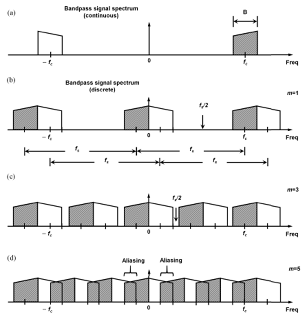
Example of spectral replications for a bandlimited signal centered at with a bandwidth at sampling below Nyquist rate. (a) Its continuous spectrum and (b)–(d) discrete spectrums with different sampling frequencies in accordance with , which is an arbitrary, positive integer satisfying .
Fig. 2 illustrates the minimum normalized sample rate curve for various . As shown in Fig. 2, the minimum acceptable sampling frequency not only decreases, as the center frequency increases, but also approaches without exceeding .
Fig. 2.

Minimum normalized sample rate curve as a function of (the normalized highest frequency in the bandpass signal) for various values of to avoid aliasing in sub-Nyquist sampling.
Similarly, a sampling frequency that satisfies (2) can also be determined as follows:
| (4) |
where is an odd positive integer and the selection of must satisfy . This property can be favorable since the sampled signal is located at one fourth the sample rate (i.e., ) [26]–[28].
In this article, the bandpass sampling rate of was chosen, since a fractional bandwidth of (i.e., ) for HFUS array transducers can be typically assumed [31], [32]. For example, for the use of a HFUS array transducer with a center frequency of bandpass sampling is performed at to sample the passband signal between and , whereas traditional sampling requires a high sampling frequency, i.e., .
B. Postfiltering-Based HFUS Beamformer With 4/3 Sampling
Conventional dynamic receive focusing typically uses a sampling frequency at four times the center frequency and interpolation (two- to fourfold) to satisfy the delay resolution (i.e., 8 to ) [12]. However, this configuration with the HFUS imaging system necessitates high-speed ADCs (e.g., a sampling rate of at ) and corresponding high-speed front-end circuits. In addition, interpolators for every channel further increase the computational complexity [8].
To address these issues, a postfiltering beamformer based on bandpass sampling is proposed to mitigate the system complexity. In addition, a polyphase filter is used for interpolator implementation to minimize the hardware burden while maintaining an adequate delay resolution. Fig. 3 represents the proposed HFUS beamformer architecture with sampling frequency. As shown in Fig. 3, to avoid unwanted spectral mixing during bandpass sampling, RF signal, , passes through the analog bandpass filter (BPF) prior to ADC. Then, the filtered analog signal is digitized by ADC at a sampling rate of , which is the minimal sampling frequency for the HFUS array transducers with a fractional bandwidth of . Coarse delays corresponding to the sampling resolution from the delay calculator are applied to read out echo data from the dual-port memories for each channel. Then, the echo data are fed into a serial-in parallel-out shift register that consists of registers, where the number of is determined by the number of taps used for interpolation. Moreover, the block data (i.e., data stored in the shift register) having the same FD (i.e., a fine delay of interpolation factor) are sent into one of the adders by 1-to- demultiplexer and are aggregated, as illustrated in Fig. 3. Each summed block data are subsequently fed into a polyphase filter for interpolation, and they are simply added for beamforming. For example, assuming that the FD of 0th and 31st channels is , these block data from two channels are sent into the third adder by demultiplexer and then fed into the corresponding polyphase filter (i.e., in Fig. 3). For the interpolation filter, a BPF was used to retain the original spectrum (see Fig. 4). With this beamformer architecture, the data rate remains at the sampling, rate while the delay resolution increases by a factor of .
Fig. 3.

Postfiltering-based HFUS beamformer architecture based on bandpass sampling. A BPF with polyphase structured filter is used as an interpolator filter to suppress spectral images.
Fig. 4.

Spectrum representations of bandpass sampling and interpolation for the bandlimited ultrasound signals in the proposed HFUS beamformer. (a) Continuous spectrum of the bandlimited signals and (b) its discrete spectrum when . (c) Spectrum result of (b) with interpolation . A BPF is used as an interpolation filter to retain the original spectrum.
Fig. 4 illustrates spectrum representation of the sampling and interpolation for a bandlimited signal () centered at . As shown in Fig. 4(a) and (b), the bandlimited signal in the continuous domain is aliased by bandpass sampling with a sampling frequency of ; the desired signal is reversed (folded) and lies into the band below Nyquist frequency in the discrete domain. However, the sampling still maintains the desired signal components by selecting the Nyquist frequency below the lower edge of the transducer’s passband . Therefore, analog BPF prior to the ADC (see Fig. 3), which is required to limit the out-of-band frequency noise, can directly impact the sensitivity, resolution, and beamforming accuracy. For practical implementation, a combination of a conventional analog antialiasing low-pass filter (typically per octave roll-off) and a high-pass filter in analog front-end (AFE) in a modern ultrasound system can be used for BPF [31]. Consequently, up-sampling produces spectral images by a factor of and increases the delay resolution (i.e., at ). These spectral replicas can be filtered out by BPF, as illustrated in Fig. 4(c).
C. Experimental Setup
Simulation, in vitro and in vivo experiments were conducted using ultrafast coherent compounding imaging, where 21 plane waves with steering angles ranging from to were used. The proposed postfiltering-based HFUS beamformer with bandpass sampling and the interpolation beamformer with Nyquist sampling were compared for evaluation. The delay resolution of the proposed method was set to (i.e., sixfold interpolation with sampling frequency), whereas the conventional approach was implemented with (i.e., fourfold interpolation at sampling frequency). Hanning apodization was used for both the methods.
In the Field II simulation [33], five-point targets were placed in the center region, and pre-beamformed RF data were generated using 256-element HFUS transducer with an element pitch of . The center frequency was 31.25 MHz. The sampling frequency of the conventional beamformer was , while the sampling frequency was for the bandpass sampling beamformer. With these two beamformers, three transmit pulses with different numbers of cycles (one, two, and three) were applied to two transducers with fractional bandwidths of and , respectively, for quantitative evaluation. In addition to the point target simulation, cyst targets were simulated to measure the contrast-to-noise ratio (CNR), which is defined as
| (5) |
where and are the average intensities in the cyst and speckle regions, respectively, and and are the variances of each region.
For the in vitro and in vivo experiments, a single-wire target phantom and a murine model of primary breast cancer were scanned using a preclinical high-frequency (20–46 MHz) linear array transducer (MX400, FUJIFILM VisualSonics Inc., Toronto, ON, Canada). Animal procedures were conducted in accordance with the policies of the Institutional Animal Care and Use (IACUC) of the Georgia Institute of Technology (Protocol A16018). Transmit pulses with one to three cycles were used to compare the spatial resolution similar to the simulation study. Each RF data at the sampling frequencies of and were obtained using an ultrasound programmable research platform (Vantage 256, Verasonics Inc., Redmond, WA, USA). To achieve sampling frequency, interleaved acquisitions by two transmissions were used since the ADC rate was limited to in the system [31].
To quantitatively assess the image quality, spatial resolution and were used. The axial and lateral profiles at the point target regions were plotted, and the axial resolutions were measured from the envelope signals.
III. Results
A. Simulation Study
Fig. 5 represents the B-mode results (a dynamic range of of coherent compounding imaging from three transmit pulse cycles (i.e., one, two, and three cycles) with the transducer bandwidth of . Fig. 5(a) shows the results of the conventional interpolation beamformer with the delay resolution of based on Nyquist sampling , and Fig. 5(b) shows the results of the postfiltering-based HFUS beamformer with the delay resolution of using sub-Nyquist sampling . Overall, the bandpass sampling approach produced visually similar image quality to the conventional beamformer for all the three cases (i.e., one to three transmit cycles). However, the bandpass sampling beamformer slightly increased sidelobes along the axial direction for the near-field targets (i.e., 2, 4, and ). These sidelobe levels decreased as the pulse duration (or the pulse cycle) increased, as shown in Fig. 5(b).
Fig. 5.

Simulation results (five-point targets) for plane wave B-mode imaging reconstructed by (a) conventional interpolation beamformer with Nyquist sampling and (b) postfiltering-based beamformer with bandpass sampling with different transmit pulse cycles (i.e., one, two, and three) using the transducer with a fractional bandwidth of .
The axial and lateral profiles from the point target at a depth of were also plotted as shown in Fig. 6. Fig. 6(a) illustrates the axial profiles and Fig. 6(b) the lateral profiles. In the axial profiles, a main lobe width was slightly broadened, as the number of pulse cycles increased for both the methods (i.e., conventional Nyquist sampling and bandpass sampling). The main lobe width of the bandpass sampling (4/3x sampling) was similar to that of the conventional method (4x sampling) for all three cycles, as depicted in Fig. 6(a). However, sidelobes along the axial direction, which are generally shown in ultrafast coherent compounding method as a clutter noise [34], increased compared to the conventional method as indicated by the arrows in Fig. 6(a). These sidelobe levels were reduced with increasing the pulse duration. For the lateral profiles, the same −6-dB resolutions were obtained from the conventional and proposed beamformer for all three transmit pulses.
Fig. 6.
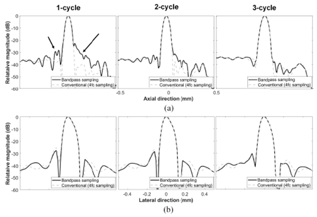
(a) Axial and (b) lateral profiles according to the pulse duration (one to three cycles) from the point target located at in Fig. 5.
A transducer with a fractional bandwidth of was also simulated to investigate the potential of wide bandwidth transducers. Fig. 7 represents B-mode images reconstructed by the conventional and bandpass sampling methods. Compared with the transducer with a fractional bandwidth of , the sidelobes along the axial direction were further noticeable in the bandpass sampling method. These sidelobe levels decreased as the pulse duration increased, which is similar to the previous results in Fig. 5. Fig. 8 also illustrates the axial and lateral profiles for the point target located at . Despite the increased fractional bandwidth (from to ), the axial main lobe width of the bandpass sampling was comparable to the conventional sampling for all three transmit pulse cycles. These axial main lobes increased as the pulse duration increased, as shown in Fig. 8(a). The sidelobe levels of the bandpass sampling were increased due to the wide fractional bandwidth of the transducer, as indicated by the arrows in Fig. 8(a), and the sidelobe levels decreased as the number of pulse cycles increased. The −6-dB lateral resolution profiles for the two beamformers were identical, as illustrated in Fig. 8(b).
Fig. 7.

Simulation results (five-point target) for plane wave B-mode imaging reconstructed by (a) conventional interpolation beamformer with Nyquist sampling and (b) postfiltering-based beamformer with bandpass sampling with different transmit pulse cycles (i.e., one, two, and three) using the transducer with a fractional bandwidth of .
Fig. 8.

(a) Axial and (b) lateral profiles according to the pulse duration (one to three cycles) from the point target located at in Fig. 7.
The axial beam widths at were measured to quantify the resolution of two beamformers with two sampling rates versus . Fig. 9 shows the measurement results as a function of transmit pulse cycles (one to three) for the transducer with two fractional bandwidths of and 98%. As shown in Fig. 9(a) and (b), the transducer with wider bandwidth () showed overall slightly narrower beam widths than those by the transducer with a bandwidth of for all cases. The axial beamwidth increased, as the transmit pulse cycle (i.e., pulse duration) increased. The postfiltering-based beamformer based on bandpass sampling (solid lines) showed marginally thicker beam widths over the conventional beamformer (dashed lines). For example, axial beamwidths for two methods were 63.5 and , respectively, with a bandwidth transducer, and with a bandwidth transducer when the two-cycle transmit pulse was used, respectively. The same axial beam widths were achieved for the three-cycle pulse.
Fig. 9.

Measured −6-dB axial resolutions for the two beamformers (i.e., conventional beamformer with sampling versus HFUS beamformer with sampling) as a function of the number of transmit cycles in the fractional bandwidth of (a) and (b) , respectively.
Fig. 10 shows the simulated cyst phantom images by the transducer with a fractional bandwidth of . Under visual assessment, it is difficult to identify a difference between the conventional [see Fig. 10(a)] and postfiltering-based HFUS beamformers with sub-Nyquist sampling [see Fig. 10(b)]. To quantitatively compare the performance, we measured the CNR values from the regions indicated with white circles for each image and they are listed in Table I. The same CNRs were obtained from two- and three-cycle transmission, but a slightly lower CNR value was measured for the one-cycle case in the proposed method because of its increased axial sidelobe. Similar results were obtained from the transducer with fractional bandwidth.
Fig. 10.

Simulation results (cyst phantom) by (a) conventional interpolation beamformer with Nyquist sampling and (b) postfiltering-based beamformer with bandpass sampling according to the transmit pulse cycles (i.e., one, two, and three) at a fractional bandwidth of .
TABLE I.
CNR Values From Simulated Cyst Phantoms by the Conventional (Conv.) and Proposed Methods
| Fractional bandwidth | Method | CNR | ||
|---|---|---|---|---|
| 1-cycle | 2-cycle | 3-cycle | ||
| Conv. | 0.28 | 0.32 | 0.37 | |
| Proposed | 0.27 | 0.32 | 0.37 | |
|
| ||||
| Conv. | 0.19 | 0.27 | 0.36 | |
| Proposed | 0.17 | 0.27 | 0.36 | |
B. In Vitro and in Vivo Studies
Similar to the simulation study, the performance of postfiltering-based beamformer based on sub-Nyquist sampling was compared with that of the conventional interpolation beamformer with Nyquist sampling using a custom-made single wire phantom and a small animal model (i.e., a murine model of breast cancer). Fig. 11 represents the B-mode results (a dynamic range of ) of the wire phantom acquired using a commercialized high-frequency linear array transducer (MX400, FUJIFILM VisualSonics Inc., Toronto, ON, Canada). Although the computational complexity was considerably reduced by the proposed beamformer architecture (data rate , thus threefold reduction in computational complexity), the image quality was preserved in the proposed approach, as shown in Fig. 11.
Fig. 11.

Simulation results (cyst phantom) by (a) conventional interpolation beamformer with Nyquist sampling and (b) postfiltering-based beamformer with bandpass sampling according to the transmit pulse cycles (i.e., one, two, and three) at a fractional bandwidth of .
Fig. 12(a) illustrates the axial profiles from the conventional and proposed methods with two sampling rates, and Fig. 12(b) depicts the lateral profiles. For the axial profiles, the main lobe widths of the bandpass sampling approach (solid lines) were similar to those of the conventional approach (dashed lines) for all cycle cases. The axial resolution decreased, as the pulse duration increased. However, the sidelobe along the axial direction, which is one of clutter noise in plane wave imaging, was more pronounced in the bandpass sampling method, as indicated by the arrow in Fig. 12(a). The sidelobe level decreased, as the number of transmit cycle increased. The lateral resolutions from the two approaches were the same for all three cases, as depicted in Fig. 12(b), which was consistent to the simulation results.
Fig. 12.

(a) Axial and (b) lateral profiles in accordance with the pulse duration (one to three cycles) from the point target results in Fig. 11.
The axial resolutions were measured for quantitative comparison. Fig. 13 shows the measured values for each beamformer as a function of the transmit pulse cycle (one to three). As illustrated in Fig. 13, the bandpass-sampling-based beamformer produced a larger axial beamwidth over the conventional beamformer. The axial resolutions with the two-cycle pulse were 59.5 and for the proposed and conventional methods, respectively. From the simulation and in vitro experiments, it was found that in the two-cycle transmission, there were slightly larger axial beam widths and lower sidelobe levels compared with those by the one-cycle transmission.
Fig. 13.

Measured −6-dB axial resolutions for the two beamformers (i.e., conventional beamformer with sampling versus HFUS beamformer with sampling) as a function of the number of transmit cycles in the in vitro study.
Fig. 14 shows the in vivo B-mode imaging results with a dynamic range of from the conventional and proposed beamformers from a thigh region of a tumor-bearing mouse model. In this experiment, we used a two-cycle transmit pulse for both the methods. The HFUS beamformer based on bandpass sampling produced the comparable image quality to the conventional interpolation beamformer. The hyperechoic regions from muscle fibers were clearly visualized in both the images. Hypoechoic and anechoic regions from the tumor were successfully reconstructed for both the beamformers with appropriate speckle representation. For quantitative comparison, CNRs were measured from the regions indicated with white boxes. Consistent with the visual assessment, similar CNR values were obtained; they were 1.46 and 1.42 for the conventional and proposed bandpass sampling methods, respectively.
Fig. 14.

In vivo B-mode imaging results using (a) conventional interpolation beamformer with Nyquist sampling and (b) proposed HFUS beamformer with bandpass sampling in a thigh region of a tumor-bearing mouse model.
IV. Discussion
In this article, a postfiltering-based HFUS beamformer using sub-Nyquist sampling was proposed. To lower the computational complexity while increasing delay resolution in beamforming, a polyphase structure was also implemented to support the interpolation process. Thus, threefold data rate reduction was achieved. Due to the attribute of the bandlimited signal, bandpass sampling can be a feasible solution for ultrasound imaging. Using sub-Nyquist sampling, Fourier domain beamforming techniques based on compressive sensing have been recently proposed and used in a wireless ultrasound system [22]–[25]. More recently, bandpass sampling was applied to Doppler imaging application and marginal differences were observed in color flow imaging and vector flow imaging [30]. Although RF bandpass sampling techniques with a limited ADC sampling rate (bandwidth sampling and interleaved acquisition) were previously presented for HFUS transducers [31], no image quality evaluation or feasibility studies for HFUS imaging have been reported.
From the simulation and in vitro imaging experiments, the qualitative and quantitative assessment was conducted using point targets and cysts. The sidelobes along the axial direction by the bandpass sampling technique increased with a wideband excitation pulse (i.e., one transmit cycle), whereas the main lobe widths were comparable to the conventional method, as the spectral components out of the sampling bandwidth such as noise or signal boundaries were aliased during bandpass sampling . Note that we used a BPF with fractional bandwidth of in the simulation, and thus, the spectral contents out of band can still exist. Thus, the axial and sidelobe levels were further increased by the wider transducer bandwidth (i.e., 98%), as illustrated in Figs. 7 and 8. The lateral beam widths of the bandpass sampling were identical to those of the conventional sampling, since it is determined by the center frequency and the transmit configuration (i.e., angle spans in plane wave imaging [35]). Although wideband HFUS array transducers have been introduced for various applications, the nominal fractional bandwidth for commercial HFUS array transducer over is still not as typical as general clinical transducers because of technical difficulties in fabrication [36]–[38]. For the in vivo results from the commercial HFUS array transducer (MX400, FUJIFILM VisualSonics Inc., Toronto, ON, Canada), the image quality including speckle representation for the bandpass sampling method was similar to that of the conventional Nyquist sampling method ( ) as illustrated in Fig. 14.
One of the limitations in this study is that we relied on the transducer specifications, provided by the manufacturer. The bandwidth of the transducer was , which does not meet the bandwidth requirement. In the in vitro results, the axial resolutions at for one- and two-cycle transmission were identical. With this, it can be assumed that the bandwidth of the transducer was not measured at , which could lead to a discrepancy between the simulation and experimental results.
Although the HFUS beamformer based on sub-Nyquist sampling reduced the computational complexity in terms of sampling rate, memory size, and beamforming samples, it has several limitations. First, the implementation of greater interpolation to obtain sufficient delay resolution may introduce more interpolation errors. Moreover, additional analog BPF prior to sampling to limit the signal bandwidth may increase the hardware complexity. In addition, the out-of-band frequency components could be aliased during signal processing including fractional decimation after beamforming. Our on-going study is to implement a real-time HFUS system that is cost-effective and suitable for portable designs. In addition, the efficient HFUS beamformer will be applied to various applications, including photoacoustic imaging [38].
V. Conclusion
In this article, a postfiltering-based beamformer architecture with sub-Nyquist sampling was presented for efficient HFUS array imaging systems. Simulation, in vitro and in vivo studies were conducted to demonstrate the feasibility of the proposed method in HFUS applications. From these studies, we have demonstrated that the proposed method can reduce the computational complexity (threefold in beamforming), while maintaining spatial resolution and contrast for HFUS imaging.
Acknowledgments
This work was supported in part by the Korea Medical Device Development Fund Grant funded by the Korean Government (the Ministry of Science and Information and Communication Technologies (ICT), the Ministry of Trade, Industry and Energy, the Ministry of Health & Welfare, and the Ministry of Food and Drug Safety) under Grant NTIS 9991001111, in part by the National Research Foundation of Korea (NRF) Grant funded by the Korean Government (MSIP; Ministry of Science, ICT & Future Planning) under Grant NRF-2022R1C1C1012107 and Grant NRF-2021R1A6A3A14039529, in part by the National Institutes of Health under Grant R01CA149740, and in part by the Breast Cancer Research Foundation under Grant BCRF-18-043.
Footnotes
This work involved human subjects or animals in its research. Approval of all ethical and experimental procedures and protocols was granted by Institutional Animal Care and Use (IACUC) of the Georgia Institute of Technology, Protocol A16018.
Contributor Information
Jinbum Kang, uWAMIT Center, Department of Bioengineering, University of Washington, Seattle, WA 98105 USA.
Heechul Yoon, School of Electronics and Electrical Engineering, Dankook University, Yongin-si 16890, South Korea.
Changhan Yoon, Department of Biomedical Engineering, Inje University, Gimhae 50834, South Korea.
Stanislav Y. Emelianov, School of Electrical and Computer Engineering, Georgia Institute of Technology, Atlanta, GA 30332 USA; The Wallace H. Coulter Department of Biomedical Engineering, Georgia Institute of Technology and Emory University School of Medicine, Atlanta, GA 30332 USA.
References
- [1].Pavlin CJ and Foster FS, Ultrasound Biomicroscopy of the Eye. New York, NY, USA: SpringerLink, 1995 [Google Scholar]
- [2].McDaniel MC, Eshtehardi P, Sawaya FJ, Douglas JS, and Samady H, “Contemporary clinical applications of coronary intravascular ultrasound,” JACC Cardiovascular Intervent, vol. 4, no. 11, pp. 1155–1167, Nov. 2011. [DOI] [PubMed] [Google Scholar]
- [3].Foster FS, Hossack J, and Adamson SL, “Micro-ultrasound for preclinical imaging,” Interface Focus, vol. 1, no. 4, pp. 576–601, 2011. [DOI] [PMC free article] [PubMed] [Google Scholar]
- [4].Liu J-H, Jeng G-S, Wu T-K, and Li P-C, “ECG triggering and gating for ultrasonic small animal imaging,” IEEE Trans. Ultrason., Ferroelectr., Freq. Control, vol. 53, no. 9, pp. 1590–1596, Sep. 2006. [DOI] [PubMed] [Google Scholar]
- [5].Sun L, Lien C-L, Xu X, and Shung KK, “In vivo cardiac imaging of adult zebrafish using high frequency ultrasound (45–75 MHz),” Ultrasound Med. Biol, vol. 34, no. 1, pp. 31–39, Jan. 2008. [DOI] [PMC free article] [PubMed] [Google Scholar]
- [6].Qiu W, Yu Y, Tsang FK, and Sun L, “An FPGA-based open platform for ultrasound biomicroscopy,’ IEEE Trans. Ultrason., Ferroelectr., Freq. Control, vol. 59, no. 7, pp. 1432–1442, Jul. 2012. [DOI] [PubMed] [Google Scholar]
- [7].Hu CH, Snook KA, Cao P-J, and Shung KK, “High-frequency ultrasound annular array imaging—Part II: Digital beamformer design and imaging,” IEEE Trans. Ultrason., Ferroelectr., Freq. Control, vol. 53, no. 2, pp. 309–316, Feb. 2006. [DOI] [PubMed] [Google Scholar]
- [8].Yoon C, Kim HH, and Shung KK, “Development of a low-complexity, cost-effective digital beamformer architecture for high-frequency ultrasound imaging,” IEEE Trans. Ultrason., Ferroelectr., Freq. Control, vol. 64, no. 6, pp. 1002–1008, Jun. 2017. [DOI] [PubMed] [Google Scholar]
- [9].Foster FS et al. , “A new 15–50 MHz array-based micro-ultrasound scanner for preclinical imaging,” Ultrasound Med. Biol, vol. 35, no. 10, pp. 1700–1708, Oct. 2009. [DOI] [PubMed] [Google Scholar]
- [10].Zhang L et al. , “A high-frequency, high frame rate duplex ultrasound linear array imaging system for small animal imaging,” IEEE Trans. Ultrason., Ferroelectr., Freq. Control, vol. 57, no. 7, pp. 1548–1557, Jul. 2010. . [DOI] [PMC free article] [PubMed] [Google Scholar]
- [11].Hu C, Zhang L, Cannata JM, Yen J, and Shung KK, “Development of a 64 channel ultrasonic high frequency linear array imaging system,” Ultrasonics, vol. 51, no. 8, pp. 953–959, Dec. 2011. [DOI] [PMC free article] [PubMed] [Google Scholar]
- [12].Steinberg BD, “Digital beamforming in ultrasound,” IEEE Trans Ultrason., Ferroelectr., Freq. Control, vol. 39, no. 6, pp. 716–721, Nov. 1992. [DOI] [PubMed] [Google Scholar]
- [13].Chernyakova T and Eldar Y, “Fourier-domain beamforming: The path to compressed ultrasound imaging,” IEEE Trans. Ultrason., Ferroelectr., Freq. Control, vol. 61, no. 8, pp. 1252–1267, Aug. 2014. [DOI] [PubMed] [Google Scholar]
- [14].Song TK and Park SB, “A new digital phased array system for dynamic focusing and steering with reduced sampling rate,” Ultrason. Imag, vol. 12, no. 1, pp. 1–16, Jan. 1990. [DOI] [PubMed] [Google Scholar]
- [15].Ranganathan K, Santy MK, Blalock TN, Hossack JA, and Walker WF, “Direct sampled I/Q beamforming for compact and very low-cost ultrasound imaging,” IEEE Trans. Ultrason., Ferroelectr., Freq. Control, vol. 51, no. 9, pp. 1082–1094, Sep. 2004 [DOI] [PubMed] [Google Scholar]
- [16].Agarwal A, Yoo YM, Schneider FK, Gao C, Koh LM, and Kim Y, “New demodulation method for efficient phase-rotation-based beamforming,” IEEE Trans. Ultrason., Ferroelectr., Freq. Control, vol. 54, no. 8, pp. 1656–1668, Aug. 2007. [DOI] [PubMed] [Google Scholar]
- [17].Ma J, Karadayi K, Ali M, and Kim Y, “Ultrasound phase rotation beamforming on multi-core DSP,” Ultrasonics, vol. 54, no. 1 , pp. 99–105, Jan. 2014 [DOI] [PubMed] [Google Scholar]
- [18].Laakso TI, Valimaki V, Karjalainen M, and Laine UK, “Splitting the unit delay [FIR/all pass filters design],” IEEE Signal Process. Mag, vol. 13, no. 1, pp. 30–60, Jan. 1996. . [Google Scholar]
- [19].Cho J, Lee J-Y, Song J-H, Kim Y, and Song T-K, “A fractional filter-based beamformer architecture using postfiltering approach to minimize hardware complexity,” IEEE Trans. Ultrason., Ferroelectr., Freq. Control, vol. 54, no. 5, pp. 1076–1079, May 2007. [DOI] [PubMed] [Google Scholar]
- [20].Jensen JA and Mathorne J, “Sampling system for in vivo ultrasound images,” Proc. SPIE, vol. 1444, pp. 221–231, May 1991. [Google Scholar]
- [21].Peyton G, Farzaneh B, Soleimani H, Boutelle MG, and Drakakis EM, “Quadrature synthetic aperture beamforming front-end for miniaturized ultrasound imaging,” IEEE Trans. Biomed. Circuits Syst, vol. 12, no. 4, pp. 871–883, Aug. 2018. [DOI] [PubMed] [Google Scholar]
- [22].Burshtein A, Birk M, Chernyakova T, Eilam A, Kempinski A, and Eldar YC, “Sub-Nyquist sampling and Fourier domain beamforming in volumetric ultrasound imaging,” IEEE Trans. Ultrason., Ferroelectr., Freq. Control, vol. 63, no. 5, pp. 703–716, May 2016. [DOI] [PubMed] [Google Scholar]
- [23].Chernyakova T et al. , “Fourier-domain beamforming and structure-based reconstruction for plane-wave imaging,” IEEE Trans. Ultrason., Ferroelectr., Freq. Control, vol. 65, no. 10, pp. 1810–1821, Oct. 2018. [DOI] [PubMed] [Google Scholar]
- [24].Wagner N, Eldar YC, and Friedman Z, “Compressed beamforming in ultrasound imaging,” IEEE Trans. Signal Process, vol. 60, no. 9, pp. 4643–4657, Sep. 2012. [Google Scholar]
- [25].Mamistvalov A and Eldar YC, “Compressed Fourier-domain convolutional beamforming for sub-Nyquist ultrasound imaging,” IEEE Trans. Ultrason., Ferroelectr., Freq. Control, vol. 69, no. 2, pp. 489–499, Feb. 2022. [DOI] [PubMed] [Google Scholar]
- [26].Vaughan RG, Scott NL, and White DR, “The theory of bandpass sampling,” IEEE Trans. Signal Process, vol. 39, no. 9, pp. 1973–1984, Sep. 1991. [Google Scholar]
- [27].Lyons RG, Understanding Digital Signals Processing. Upper Saddle River, NJ, USA: Prentice-Hall, 2011. [Google Scholar]
- [28].Mishali M and Eldar YC, “Sub-Nyquist sampling,” IEEE Signal Process. Mag, vol. 28, no. 6, pp. 98–124, Nov. 2011. [Google Scholar]
- [29].Tortoli P, Bessi L, and Guidi F, “Bidirectional Doppler signal analysis based on a single RF sampling channel,” IEEE Trans. Ultrason., Ferroelectr., Freq. Control, vol. 41, no. 1, pp. 1–3, Jan. 1994. [Google Scholar]
- [30].Madiena C, Faurie J, Poree J, and Garcia D, “Color and vector flow imaging in parallel ultrasound with sub-Nyquist sampling,” IEEE Trans. Ultrason., Ferroelectr., Freq. Control, vol. 65, no. 5, pp. 795–802, May 2018. [DOI] [PubMed] [Google Scholar]
- [31].Kaczkowski P, “Bandwidth sampling data acquisition with the Vantage system for high frequency transducers,” Verasonics, Kirkland, WA, USA, White Paper, 2016, pp. 1–5. [Online]. Available: http://verasonics.com/wp-content/uploads/2016/07/Vantage_bandwidth_sampling_white_paper_Jul.2016.pdf [Google Scholar]
- [32].Zhou Q, Lau S, Wu D, and Kirk Shung K, “Piezoelectric films for high frequency ultrasonic transducers in biomedical applications,” Prog. Mater. Sci, vol. 56, no. 2, pp. 139–174, Feb. 2011. [DOI] [PMC free article] [PubMed] [Google Scholar]
- [33].Jensen JA, “FIELD: A program for simulating ultrasound systems,” in Proc. IEEE 10th Nordic-Baltic Conf. Biomed. Imag., vol. 34, Mar. 1996, pp. 351–353. [Google Scholar]
- [34].Rodriguez-Molares A, Avdal J, Torp H, and Lovstakken L, “Axial lobes in coherent plane-wave compounding,” in Proc. IEEE Int. Ultrason. Symp. (IUS), Sep. 2016, pp. 1–4. [Google Scholar]
- [35].Kang J, Go D, Song I, and Yoo Y, “Wide field-of-view ultrafast curved array imaging using diverging waves,” IEEE Trans. Biomed. Eng vol. 67, no. 6, pp. 1638–1649, Jun. 2020. [DOI] [PubMed] [Google Scholar]
- [36].Kim HH et al. , “Characterization and evaluation of high frequency convex array transducers,” in Proc. IEEE Int. Ultrason. Symp., Oct. 2010, pp. 650–653. [Google Scholar]
- [37].Cha JH and Chang JH, “Development of 15 MHz 2–2 piezocomposite ultrasound linear array transducers for ophthalmic imaging,” Sens. Actuators A, Phys, vol. 217, pp. 39–48, Sep. 2014. [Google Scholar]
- [38].Cha JH, Kang B, Jang J, and Chang JH, “A 15-MHz 1–3 piezocomposite concave array transducer for ophthalmic imaging,” IEEE Trans. Ultrason., Ferroelectr., Freq. Control, vol. 62, no. 11, pp. 1994–2004, Nov. 2015. [DOI] [PubMed] [Google Scholar]
- [39].Lakshman M and Needles A, “Screening and quantification of the tumor microenvironment with micro-ultrasound and photoacoustic imaging,” Nature Method, vol. 12, pp. 3–5, Mar. 2015. [Google Scholar]