Abstract.
Purpose
Minimally invasive surgery has advantages in terms of quality of life and patient outcomes. Recently, near-infrared (NIR) fluorescence guided surgery has widely used for preclinical and clinical trials. However, NIR fluorescence has a maximum penetration capability of 10 mm. Radiographic imaging can be a solution to overcome the depth issue of NIR fluorescence. For this reason, the performance of the multimodal imaging system, which integrates annihilation gamma (511 keV) rays, NIR fluorescence, and color images, was evaluated.
Approach
The multimodal imaging system consisted of a laparoscopic module, containing an internal detector for annihilation gamma events and cameras for optical imaging, and a flat module for coincidence detection with the internal detector. The acquired images were integrated by an algorithm with post image processing and registration. To evaluate the performance of the proposed multimodal imaging system, the images of a resolution target, a square bar target filled with a fluorescence dye, and a sodium-22 point source were analyzed. A preclinical test for axillary sentinel lymph node (SLN) biopsy with a rat model was conducted.
Results
The spatial resolution of color images was equivalent to 4 lp/mm. The modulation transfer function of NIR fluorescence at 1 lp/mm was 0.83. The 511 keV gamma sensitivity and spatial resolution of the point source were 0.54 cps/kBq and 2.1 mm, respectively. The image of 511 keV gamma rays showed almost the same intensity regardless of the thickness of the tissue phantom. In the preclinical test, an integrated image of the SLN sample of the rat model was obtained with the proposed multimodal imaging system.
Conclusions
With the proposed laparoscopic system, a merged image of the sample was obtained with the rat model. The annihilation gamma rays showed penetration capability with the tissue-mimicking phantom superior to that of NIR fluorescence.
Keywords: multimodal imaging system, minimally invasive surgery, fluorescence guided surgery, annihilation gamma ray, image reconstruction, near-infrared fluorescence
1. Introduction
Minimally invasive surgery (MIS) with hand-assisted and robot-assisted laparoscopic surgery has advantages in terms of quality of life and patient outcomes compared to conventional open surgery.1–3 Lymph node biopsy is promising technique for the MIS procedure to diagnose initial metastasis of breast, prostate, and other cancers because of its low morbidity and mortality.4–6 Recently, image-guided surgery with fluorescence dye, which has high contrast and sensitivity, has been widely used for preclinical and clinical purposes.7–13 The guide image with the fluorescent dye offers the surgeon a clear margin of the target tissues during the intraoperative surgery. Among the fluorophores, near-infrared (NIR) fluorophores, such as the Food and Drug Administration (FDA)-approved indocyanine green (ICG), with an emission wavelength above 760 nm, are used because of their better penetration capability and sensitivity than fluorophores with an emission wavelength below 700 nm.14–16
Many commercial and developing imaging devices for intraoperative image-guided surgery provide real-time color video, fluorescence, and dual images. However, NIR fluorescence has a maximum penetration capability of 10 mm because of its low energy and interaction with scattered tissues in the human body.17–20 To overcome the tissue penetration limit of NIR fluorescence, several supplemental imaging systems have been developed with different approaches. One research group has developed a prototype hybrid probe-detecting NIR fluorescence and 140 keV gamma signals for sentinel lymph node (SLN) identification during prostate cancer surgery.21 However, this system cannot provide the gamma images, which can guide surgeons to the SLN locations more intuitively than those of gamma probes. Recently, our groups have developed hybrid laparoscopic imaging system using wavelength multiplexing method22 and ultracompact gamma camera23 to provide the simultaneous single gamma, NIR fluorescence, and visible images for SLN detection. However, those hybrid imaging systems were designed to detect single gamma photons (i.e., 140 keV), thereby limiting its applications only for single photon emission tomography radiotracers.
Several groups have developed prototype intraoperative positron emission tomography (PET) system24,25 and forceps-type coincidence detector26 to provide the fluorine-18 fluorodeoxyglucose (FDG) uptake information during cancer surgery. Recently, many types of hybrid tracers labeled as radionuclides that emit 511 keV high-energy photons and NIR fluorophores have been developed for use in intraoperative surgery.27–29 Since images with radionuclides and fluorophores labeled with specific target particles, such as proteins, enzymes, and colloids, can provide metabolic information, the MIS procedure with the hybrid tracer is an ideal technique to show the anatomical image with a real-time laparoscopic surgery and the physiological image of the distribution of the hybrid tracer. Recent studies have shown the feasibility of using hybrid images with the distribution of radionuclides and (emission) fluorescence from a hybrid tracer.30,31 In addition, a hybrid portable mini-camera32 and robot-assisted endoscopic system,33 which are suitable for the surgical environment, have also been developed for the MIS procedure. Recently, our group developed a prototype multimodal laparoscopic imaging system, which can provide the spatial information of positron emitting radionuclides and NIR fluorophores along with the white reflectance light at same time.34 The physical performance of the multimodal laparoscopic system was characterized with a phantom study demonstrating the feasibility of hybrid imaging for use in SLN detection. In this study, we present the in vivo imaging performance of the multimodal imaging system in a rodent model for SLN identification using a hybrid tracer.
2. Materials and Methods
2.1. Multimodal Imaging System with a Coincidence Detector
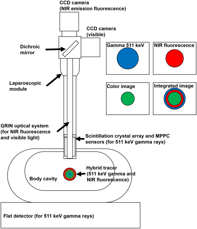
Figure 1 shows a structure of the multimodal imaging device that collects gamma events and optical signals. If a hybrid tracer that emits annihilation gamma rays and NIR fluorescence is injected into the human body, the coincidence detector and optical image sensors collect and visualize the signals of the hybrid tracer distribution. In case of gamma events, the coincidence detector, which consisted of a small detector inserted into the laparoscopic module and a flat detector placed under the body, detected a pair of annihilation gamma rays. Both detectors were coupled with the scintillation crystal array and multi-pixel photon counter (MPPC) sensors. The gamma ray entered into the crystal array produced scintillation light and generated an electric signal by the MPPC sensors. The pulse signals of the coincidence detectors were converted into pixel images using algorithms to build an event map for image reconstruction. The optical signals transferred by a gradient index (GRIN) lens system were separated into visible photons and NIR fluorescence using a dichroic beam splitter box. Two charge-coupled device (CCD) cameras attached to the edge of the beam splitter box obtained digital images of visible photons and NIR fluorescence. Each of the color (visible), NIR fluorescence, and reconstructed gamma images were subjected to post-image processing and merged into a single image in almost real time.
Fig. 1.
The structure of the multimodal imaging device with the coincidence detector.
2.2. Structure of the Coincidence (511 keV) Gamma Detector
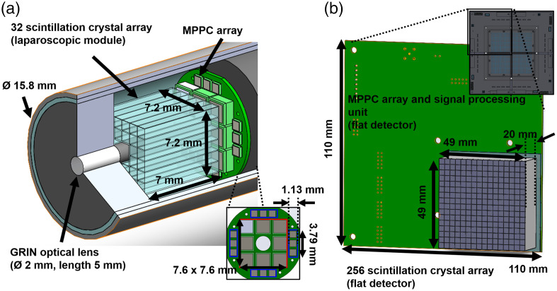
The small detector in the laparoscopic module was assembled with 32 lutetium-yttrium orthosilicate (LYSO) scintillation crystals (Epic crystal, China) of size and an array module (BASP-10006, Brightonix Imaging, South Korea) with the MPPC sensors (S13361-2050 VE and S13190-1050HDR, Hamamatsu, Japan), as shown in Fig. 2(a). To improve the collection efficiency of the edge of the crystal array, 12 MPPC sensors of the 1-mm size cell (blue box) were attached to the array module. The crystals of the whole crystal array and the whole MPPC array sensors with a 2-mm cell (red box) were removed for the GRIN optical system. The crystal array and the MPPC sensors were separated to the GRIN optical lens. Between the contact surface of the crystal array and MPPCs of the array module, a 0.5-mm thickness polyvinyl chloride lightguide was inserted with an optical grease (BC630, Saint-Gobain, France) to increase collection efficiency of scintillation light. Except for the contact surface with the MPPC sensors, all the crystal surfaces of the small detector were covered with Teflon tape of 0.1-mm thickness to prevent escaping scintillation light from the crystals. Figure 2(b) shows one block of a array of the flat detector. Each of the blocks consisted of a scintillation crystal () array coupled to the MPPC module with 16 MPPC sensors (S13361-3050 NE, Hamamatsu, Japan) and a signal processing unit (BASP-10002, Brightonix Imaging, South Korea). The signal-processing unit amplified the pulse signal of the anodes in the MPPC sensors and generated four position signals and one trigger signal. All surfaces of the crystals in the array were coated with barium sulphate (BaSO4) powder. The contact surface of the crystal array was not coated and was coupled to the MPPC module without any lightguide.
Fig. 2.
The coincidence detector: (a) the small detector in the laparoscopic module and (b) one block of the flat detector.
The analog signal from the small detector, which had four position signals, was amplified by an interface board (BASP-10004, Brightonix Imaging, Republic of South Korea), which generated a trigger pulse for coincidence detection. Through the trigger signal from the small detector and four signals from the flat detector, the coincidence trigger signal was generated by a coincidence logic (BASP-10005, Brightonix Imaging, Republic of South Korea), which has two AND gates and four OR gates with a coincidence window of 40 ns. All the trigger signals from the four blocks in the flat detector were chained to the OR gate of the logic, and the AND (coincidence) gate generated a common (coincidence) signal by the trigger signal from the small detector and the output signal of the OR gate. Twenty position signals from the coincidence detector were changed into a 12-bit digital data using a waveform digitizer (DT5740B, Caen, Italy) with a 62.5 MHz sampling rate and a maximum count rate of 2000 events.
2.3. Optical System and Image Acquisition of the Laparoscopic Module
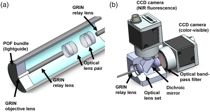
The optical system inserted into the laparoscopic module consisted of one GRIN objective lens (GRINTECH, Germany), three GRIN relay rod lenses (GRINTECH, Germany), and six achromatic lenses (Edmund Optics, United States), as shown in Fig. 3(a). The GRIN objective lens (white cylinder) had a viewing angle of 60 deg and 1.8 mm of clear aperture. The GRIN relay rod lenses with a length of 100 mm and the six optical lenses with an effective focal length (EFL) of 6 mm were used for the optical relay lens system which transports the focused optical photons by the objective lens. The surfaces between the GRIN objective lens and the first GRIN relay lens were coupled using optical cement by the manufacturer. The distance between the end of the relay lens and the principal plane of the achromatic lens was the same EFL of the achromatic lens. The edge of the laparoscopic module was filled with a plastic optical fiber (POF) bundle (Eska CK10, Mitsubishi, Japan) of 0.5 mm thickness. An NIR excitation source (M780LP1, Thorlabs, United States) and a white light source (Tunable 6500K, ScopeLED, United States) were illuminated by a POF light guide in the laparoscopic module.
Fig. 3.
The optical system of the laparoscopic module: (a) the optical parts in the laparoscopic moduel and (b) the optical parts in the image acquisition box.
Figure 3(b) shows the image acquisition box attached to the laparoscopic module, which obtains images from two types of optical photons. The transmitted optical photons were separated into NIR fluorescence and visible light using a dichroic mirror (Edmund Optics, United States) with a reflective wavelength below 800 nm. Two types of CCD cameras (Ace 800-510 uc and um, Basler, Germany) received the reflected visible photons and transmitted NIR fluorescence. Three optical lenses (Edmund Optics, United States) with an EFL of 14 mm were placed at the edge of the image-acquisition box. The distance from the end tip of the laparoscopic tip to the principal point of the first optical lens was 14 mm. The distance from optical lenses to the image planes of respective CCD cameras also was 14 mm as the relay lens with the same spot size (1.8 mm) and diverging angle (60 deg). To improve the quantum efficiency of the NIR fluorescence camera, an optical band-pass filter (Edmund Optics, United States), which has a central wavelength of 832 nm and bandwidth of 37 nm and the average optical density (OD) , was inserted in front of the CCD camera to eliminate the NIR excitation from the light source.
2.4. Image Reconstruction, Post-Processing, and Integration of 511 keV Gamma Events and Optical Signals
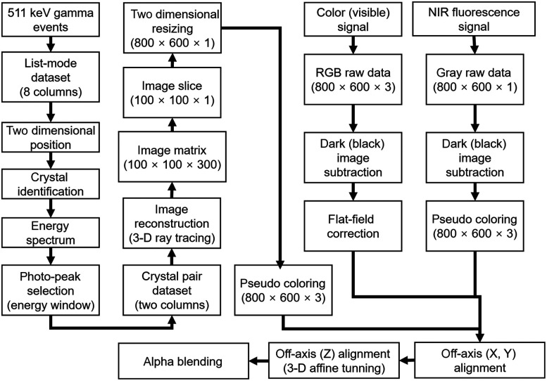
The signals from the gamma detector and respective CCD cameras were processed using an algorithm as shown in Fig. 4. Since the coincidence detector has a position-sensitive resistor chain that enables the determination of two-dimensional position data,35,36 a list-mode dataset with four signals from the laparoscopic module and 16 signals from the flat detector was changed into proportional position information. From the proportional position, the data of 32 crystals of the laparoscopic module and 1024 crystals of the flat detector were segmented, and the individual energy spectrum was calculated. Since the performance of each crystal could be different, all of the energy spectrum were aligned to an average of the total energy spectrum of the coincidence detector. From the true coincidence events selected by the energy window, a three-dimensional (3-D) image matrix was generated using a reconstruction algorithm driven by a ray-tracing method.37 An axial slice of the image with the thickness of 5 to 7 mm was resized into format, corresponding to the pixel width and height of the CCD cameras.
Fig. 4.
Schematic diagram of the image reconstruction, post-processing, and integration processes.
The digital signals of both CCD cameras with a raw 10-bit RGB and gray image were subtracted by a previously acquired dark frame that contained the readout noise and the dark current of the image sensor. The image obtained by the color camera was calibrated using a flat-field correction with three color channels because of the variation in the performance of each pixel in the CCD camera. The grayscale image from the NIR fluorescence camera was also changed to a false-color image with an 8 bit hot-green color palette for visibility. Before merging the 511 keV gamma events, NIR fluorescence, and color (visible) images, the central axis of the images was calibrated to the same point using an off-axis calibration and 3-D affine coordinate transformation method with a square grid having a line pitch of 1 mm and a checkerboard pattern with a square size of 5 mm.
2.5. Performance of NIR Fluorescence, Visible Light, and 511 keV Gamma Images with the Multimodal Imaging System
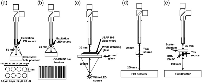
The intensity and spatial resolution of the acquired NIR fluorescence images were evaluated, as shown in Figs. 5(a) and 5(b). In the plastic phantom, which had a size of , eight circular holes with 3 mm diameter and 3 mm depth were filled with a solution of dimethyl sulfoxide (DMSO) and ICG powder. The molar concentration (M) of each hole is shown in Fig. 5(a). To calculate the spatial resolution of the NIR fluorescence image, a plastic phantom covered with a plastic bar target of size was filled with the same ICG-DMSO solution with a molar concentration of . There were nine groups of three square holes, which have widths of 1, 0.89, 0.79, 0.71, 0.63, 0.56, 0.5, 0.45, and 0.41 mm in the plastic bar target. The width of 27 bars was equivalent to the line pair per millimeter (lp/mm) of 0.5 to 1.22.
Fig. 5.
The performance evaluation of the proposed multimodal imaging system: (a) the intensity of the NIR fluorescence image, (b) the spatial resolution of the NIR fluorescence image, (c) the performance of the color (visible) image, (d) the performance of the 511 keV gamma image, and (e) the penetration depth with a tissue mimicking phantom.
To evaluate the color image obtained by the visible CCD camera, an image of the United States Air Force (USAF) 1951 glass slide resolution target (Edmund Optics, United States) with an area of was obtained, as shown in Fig. 5(c). A white diffusing glass (Edmund Optics, United States) with a transmission efficiency (TE) of 30% at 550 nm and a ground glass (Edmund Optics, United States) with TE of 70% at 550 nm were placed under the resolution target for uniform distribution of visible photons from the back-illuminated white light source. The spatial resolution of the optical images was calculated using the modulation transfer function (MTF) with one-dimensional (1-D) line profiles of the resolution bars on the NIR phantom and USAF 1951 resolution target
| (1) |
where and are the maximum and minimum pixel intensity of the line profile, respectively. The exposure times of the visible and NIR fluorescence cameras were 50 and 100 ms, respectively.
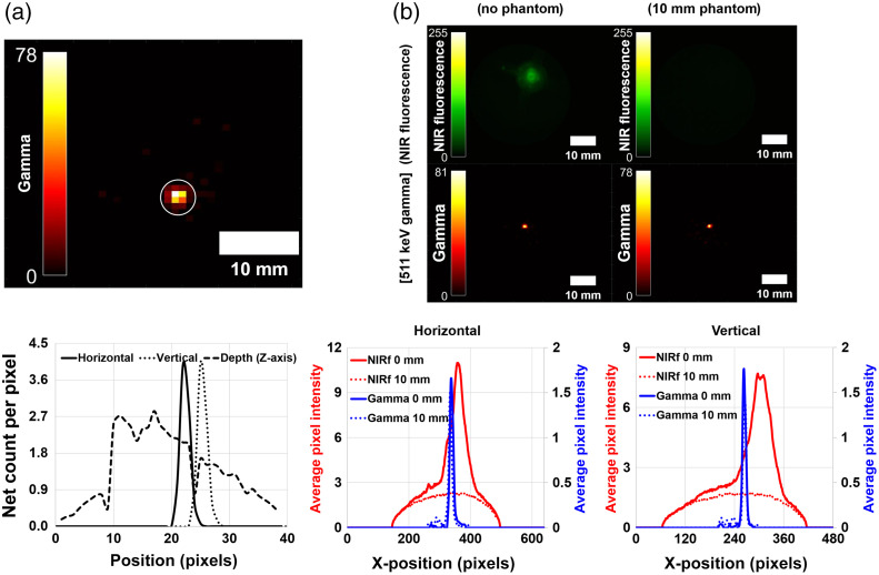
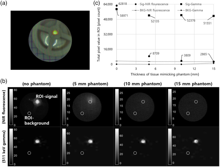
Through the acquired image of a sodium-22 point source with 1.5 mm diameter, the performance of the 511 keV gamma image signal was evaluated, as described in Fig. 5(d). The distances from the point source to the end tip of the laparoscopic module and from point source to the flat detector were 30 and 200 mm, respectively. To evaluate spatial resolution, the gamma image with acquisition time of 60 s was used to obtain sufficient events, instead of 1 s which is appropriate for real-time display in the intraoperative surgery. The sensitivity and the full width of half maximum of the 1-D line profile were obtained at a distance of 30 mm. The penetration capability of 511 keV gamma rays was evaluated with the image of NIRF fluorescence and 511 keV gamma covered with three tissue-mimicking phantoms which has an area of and a thickness of 5, 10, and 15 mm. The phantom, consisting of 89% water, 10% porcine skin gelatin powder (Sigma Aldrich, United States), and 1% intralipid 20% (JW Pharmaceutical, South Korea), was stirred continuously for 30 min at 37°C and cooled at room temperature (24°C) for 20 h. The phantom was placed on the point source, and a plastic phantom with a 3 mm diameter hole was placed under the point source. The acquisition time of respective images for penetration depth evaluation were the same as the acquisition time with an evaluation of optical and gamma images. The NIR fluorescence and annihilation gamma images were resized for the same field-of-view of the images. The total number of pixels was calculated in the images with region of interest (ROI) corresponding to the ICG source point. The total pixel value in the background ROI was also calculated.
2.6. Image of the Multimodal System with the Coincidence Detector for NIR Fluorescence Guide Image: A Feasibility Preclinical Test
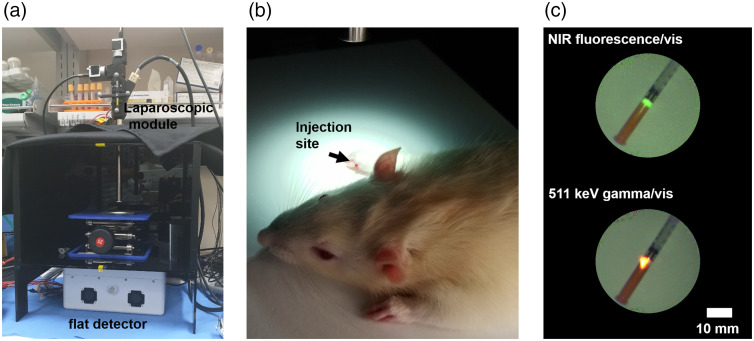
To validate the feasibility of fluorescence guided laparoscopic surgery with the 511 keV gamma image, a preclinical study using a rat model for SLN biopsy was performed, as shown in Fig. 6. In a dark box made of black acrylic plastic, the laparoscopic module and the flat detector were placed with an aluminum support jack [Fig. 6(a)]. The hybrid tracer was injected subcutaneously into the right front foot of the anesthetized rat [Fig. 6(b)]. The 0.7 mg -mannosylated human serum albumin (MSA)38 with an activity of 5.5 MBq was labeled using a commercial ICG labeling kit ( kit, Dojindo Molecular Technologies, Japan) for bifunctional imaging. The labeling process of the ICG kit radiopharmaceuticals was performed according to the manufacturer’s instruction. Ratio of ICG and -MSA was determined by the following equation:
| (2) |
where and are absorbance at 280 and 800 nm. The symbol represents the molar absorption coefficient of protein at 280 nm. Figure 6(c) shows an image of NIR fluorescence (top) emitted by ICG and 511 keV gamma (bottom) of the radionuclide in the hybrid tracer. Approximately 2 h after injection, an SLN sample was dissected, and a merged image of the sample was also acquired. All the preparation and protocol for the preclinical test were supervised by the Seoul National University Bundang Hospital and approved by the Institutional Animal Care and Use Committee (IACUC) (MSRI-53-15-020).
Fig. 6.
Setup of the preclincal test: (a) the laparoscopic module and the flat detector, (b) injection site of the rat model, and (c) acquired images of the hybrid tracer labeled with NIR fluorescence (top) and 511 keV gamma rays (bottom).
3. Results
3.1. Performance of the Color (Visible) Image with the USAF 1951 Target
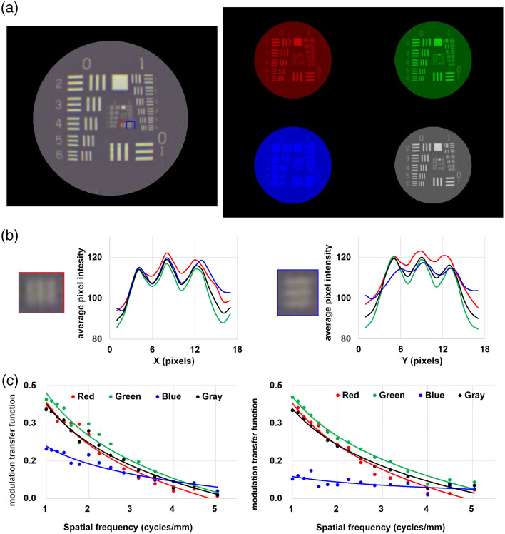
In the color (visible) image of the USAF 1951 resolution target as shown in Fig. 7(a), the three bars in the horizontal (red box) and vertical (blue box) directions in the group 2 and element 1 equivalent to 4 lp/mm were identified [Fig. 7(b)]. The vertical resolution of the blue channel was worse than those of color channels because of the low reflectance of the dichroic mirror at wavelength below 400 nm. The measured MTF and logarithmic curve of all groups and elements in the resolution target were measured, as shown in Fig. 7(c). The MTF of the blue channel was for any groups and elements. Since the dichroic mirror has a high TE at a wavelength of 450 nm, to 40% of blue light can be transmitted, but not reflected. The MTF of the grayscale image at group 0, element 1 and group 2, element 3 was 0.35 and 0.01, respectively.
Fig. 7.
The performance of color (visible) image: (a) the color (left), individual RGB channels, and grayscale (right) images of the USAF 1951 resolution target, (b) 1-D line profile in the ROI, and (c) MTF curves of the acquired image.
3.2. Spatial Resolution and Intensity Measurement of NIR Fluorescence Image
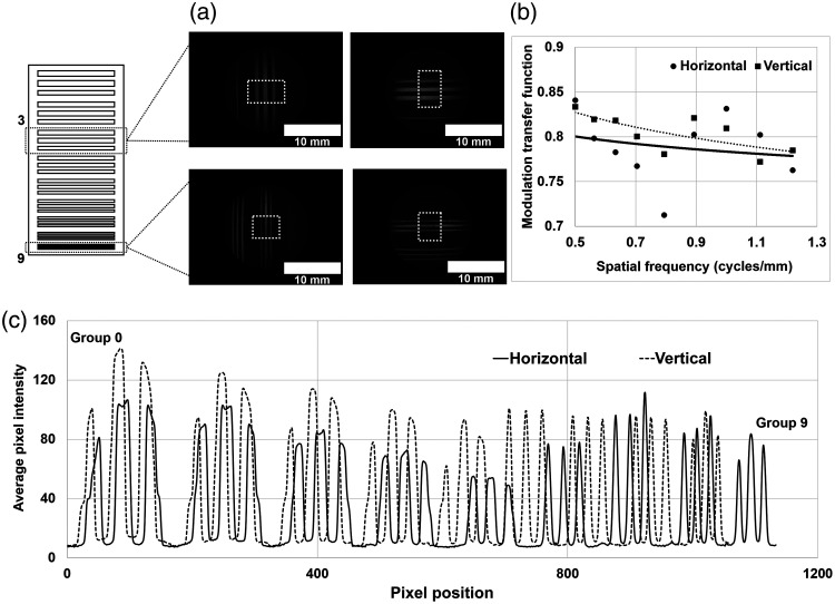
In the acquired image of the bar target containing the ICG-DMSO solution, the horizontal and vertical lines in the three bars are observed [Fig. 8(a)]. To evaluate the spatial resolution of the 27 bars in the image, the images were used in the ROI at the center of the 3 bars (white dotted-line). The measured MTF of three bars at 0.5 and 1.21 lp/mm was 0.83 and 0.78, respectively [Fig. 8(b)]. The measured MTF of NIR fluorescence and the color (visible) image at 1 lp/mm was 0.83 and 0.35, respectively, because the background signal of the NIR fluorescence image was lower than the background signal of the color image. Figure 8(c) shows the 1-D line profile in the horizontal (solid line) and vertical (dashed line) direction. All the line profiles of the three bars in the nine bar groups were resolved clearly without the partial volume effect. The intensities of the three bars in groups 3, 4, and 5 were lower than those in groups 7, 8, and 9 because of the non-uniform distribution of the ICG-DMSO solution. The maximum intensity in the vertical direction was higher than that in the horizontal direction because of the different spatial resolution of the image sensors in the CCD cameras.
Fig. 8.
The spatial resolution of NIR fluorescence image: (a) the image of the bar target, (b) the MTF curve of the image, and (c) the 1-D intensity curve of the image.
The acquired image of the plastic hole phantom is shown in Fig. 9(a). In the 3-D surface plot shown in Fig. 9(b), the intensity of NIR fluorescence increased with increased ICG concentration. The average pixel count was calculated for the eight ROI in the image (white-circle), as shown in Fig. 9(c). The average pixel count at 5 and 10 μM did not show linear growth because of the non-uniform exposure to the NIR excitation light. The maximum average pixel count was obtained at . In contrast, the average pixel count at 50 and was lower than that at because of the concentration-dependent quenching effect.39
Fig. 9.
The intensity measurement of NIR fluorescence image: (a) the acquired image of ICG-DMSO solution, (b) 3-D surface plot of the image, and (c) the bar graph of intensity in the ROI.
3.3. Performance and Penetration Capability of the 511 keV Gamma Ray Image
The reconstructed transaxial image of a Na-22 point source with a slice thickness of 7 mm is shown in Fig. 10(a). At the ROI (white circle) in the 511 keV gamma image, the sensitivity of the point source, which has an activity of 137 kBq, was 0.54 cps/kBq, and the spatial resolution of the point source with 1.5 mm diameter was 2.1 mm in the horizontal direction, 2.1 mm in the vertical direction, and 23.5 mm in the depth (z-axis) direction. The energy resolution of the coincidence detector was at 24°C. The penetration capability of the 511 keV gamma rays was evaluated using the obtained rescaled gamma images and NIR fluorescence images [Fig. 10(b)]. There were no signals in the image (top-right) covered in the 10-mm tissue phantom for NIR fluorescence. The average pixel intensity of the NIR fluorescence covered with the tissue phantom was of the average pixel intensity without the tissue phantom. However, the image of 511 keV gamma rays showed almost the same intensity regardless of the thickness of the tissue phantom.
Fig. 10.
The image and the line profile of (a) the Na-22 point source and (b) the existence of the tissue phantom.
Figure 11 shows the acquired image with the scatter phantom for comparison of penetration depth between NIR fluorescence and an annihilation gamma ray. Before the registration of all images, as shown in Fig. 11(a), grayscale images were individually obtained. In the circular ROI (white line) with a diameter of 18 pixels, the total pixel value was calculated for evaluation of pixel intensity with the scatter phantom. Figure 11(c) shows the total pixel intensity of NIR fluorescence and gamma images in the ROI with the 5, 10, and 15 mm scatter phantom. The pixel intensity of the gamma ray image was not affected by the scatter phantom, and the pixel intensity with the 15-mm scatter phantom was 87% of the intensity without the scatter phantom. However, the pixel intensity of NIR fluorescence with the 5-mm scatter phantom was only 13% of the intensity without the scatter phantom.
Fig. 11.
Comparison of penetration depth with the tissue phantom: (a) a snapshot (8-bit) of the acquired phantom image, (b) the acquired grayscale image of NIR fluorescence (top) and 511 keV gamma rays (bottom), and (c) the total pixel value in the ROI (white line).
3.4. SLN Biopsy with the Rat Model
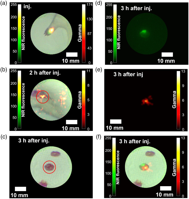
Figures 12(a)–12(f) show the images obtained during SLN biopsy with the rat model. The exposure times of the coincidence detector, the NIR fluorescence camera, and the color (visible) camera were 1 s, 130 ms, and 50 ms, respectively. Since the sensitivity of the coincidence detector is poorer than those of the respective CCD cameras, the gamma image was updated asynchronously every second. After the injection, the merged color image with NIR fluorescence and 511 keV gamma rays showed the injection site in the right foot of the rat model [Fig. 12(a)]. With the acquired image in Fig. 12(b), one SLN sample was dissected from one of the hot spots (red circle). Figure 12(c) shows color image of the biopsied SLN sample. From the NIRF fluorescence image [Fig. 12(d)] and 511 keV gamma image [Fig. 12(e)], an integrated image [Fig. 12(f)] was obtained by the registration algorithm as described in Sec. 2.4.
Fig. 12.
The images of the preclinical study with the rat model: (a) right after injection, (b) 2 h later, (c)–(e) a dissected sample of SLN (color, NIR fluorescence, and gamma) 3 h later, and (f) a merged image of the SLN sample.
4. Discussion
For NIR fluorescence guided laparoscopic surgery, the penetration capability of NIR fluorescence has been questioned because of its low energy and interaction with other organs, which causes scattering in the tissues. Some reports show that conventional laparoscopic surgery with NIR fluorescence is not sufficient for visualization of lesions because of limited penetration depth caused by thick tissues.40,41 A number of approaches have been adopted to overcome the penetration depth problem of NIR fluorescence.42 Brouwer et al. reported that navigation system with preoperative radiographic image for NIR fluorescence-guided laparoscopic surgery can compensate the limited penetration depth of NIR fluorescence.43 However, the repositioning error during image registration still exists caused by respiration and movement of patient. Kose et al. suggested that a laparoscopic ultrasound guided image can help visualizing deep lesions, and a NIR fluorescence guide image is suitable for detection of superficial lesions.44 Although the ultrasound image provides anatomical structure of deeper tissues, it does not show physiological information on specific uptake of certain diseases, such as a cancer. Radiographic imaging with a radioisotope can be a solution to overcome this issue because of its penetration depth in the human body and the possibility of labeling the fluorescent dye and radionuclide with a specific particle.
Nevertheless, patient and occupational exposure is another issue for radio-guided surgery. For the clinical use of radioisotopes that emit 511 keV annihilation gamma rays for PET imaging, a recent study showed that occupational exposure is relatively smaller than the recommended annual exposure limit provided by the International Commission on Radiological Protection guidelines.45 The radiation exposure during intraoperative imaging and surgery can be manageable because most radionuclides that emit annihilation gamma photons have a short lifetime of 2 h. Furthermore, a low-dose injection can be achieved by direct injection to increase the dose delivered to the target lesion during intraoperative surgery.46
With the multimodal system with the coincidence detector, the Na-22 point source images, the plastic phantom containing the ICG-DMSO solution, and the rat model injected with the Ga-68/NOTA-MSA/ICG-NH2 hybrid tracer were obtained. In the evaluation of the optical images and the reconstructed gamma-ray image, the intensity of the blue channel in the color image was lower than that in the other color channels. Since the dichroic mirror in the laparoscopic module had a high TE at the wavelengths of 300 to 420 nm, to 40% of photons with wavelength below 420 nm were transmitted to the mirror. To evaluate the performance of the gamma image, the spatial resolution of the reconstructed gamma image in the z-axis (depth) direction was . Since the area of the small detector in the laparoscopic module was far smaller than that of the flat detector, the response of the small detector can be worse than that of the flat detector. The deterioration of the angular response of the coincidence detector is dependent on the distance between the radioactive point and the small detector. For better spatial resolution in the depth direction, the time-of-flight (TOF) method, which removes the noise signals from the reconstructed image, can be one of the solutions.
5. Conclusion
With the proposed laparoscopic system with the coincidence gamma detector for NIR fluorescence-guided surgery, integrated 511 keV gamma rays, NIR fluorescence, and color images were acquired. The annihilation gamma rays showed better penetration capability with the tissue-mimicking phantom than with NIR fluorescence. A merged image of the SLN sample was obtained using the proposed multimodal system in the preclinical testing with the rat model injected with the hybrid tracer.
Acknowledgments
This research was funded by National Research Foundation (NRF) of Korea of the Ministry of Science, ICT and Future Planning, Nuclear R&D Program (Grant No. NRF-2016M2A2A4A03913619); National Research Foundation (NRF) of Korea of the Ministry of Science, ICT and Future Planning, Nuclear R&D Program (Grant No. NRF-2020R1F1A1054317); and Korea Medical Device Development Fund grant funded by the Korea government (the Ministry of Science and ICT, the Ministry of Trade, Industry and Energy, the Ministry of Health and Welfare, the Ministry of Food and Drug Safety) (Grant Nos. KMDF_PR_20200901_0087 and 1711138120).
Biographies
Seong Hyun Song is a researcher at Eulji University. He received his BS degrees in radiological science from Eulji University in 2015, and his MS and PhD degrees in senior healthcare from Graduate School of Eulji University in 2018 and 2022, respectively. His current research interests include medical imaging, radiographic imaging, and nuclear medicine.
Biographies of the other authors are not available.
Disclosures
The authors declare no conflict of interest.
Contributor Information
Seong Hyun Song, Email: chungak@naver.com.
Seong Jong Hong, Email: hongseongj@gmail.com.
Ho Young Lee, Email: debobkr@gmail.com.
Han Gyu Kang, Email: hangyookang@gmail.com.
Young Been Han, Email: asjkbd@naver.com.
References
- 1.Veldkamp R., et al. , “Laparoscopic surgery versus open surgery for colon cancer: short-term outcomes of a randomised trial,” Lancet Oncol. 6, 477–484 (2005). 10.1016/S1470-2045(05)70221-7 [DOI] [PubMed] [Google Scholar]
- 2.Peng Y., et al. , “Outcomes of laparoscopic repeat liver resection for recurrent liver cancer: a system review and meta-analysis,” Medicine-Baltimore 98, e17533 (2019). 10.1097/MD.0000000000017533 [DOI] [PMC free article] [PubMed] [Google Scholar]
- 3.Magrina J. F., “Outcomes of laparoscopic treatment for endometrial cancer,” Curr. Opin. Obstet. Gynecol. 17, 343–346 (2005). 10.1097/01.gco.0000175350.18308.73 [DOI] [PubMed] [Google Scholar]
- 4.Wyler S. F., et al. , “Laparoscopic extended pelvic lymph node dissection for high-risk prostate cancer,” Urology 68, 883–887 (2006). 10.1016/j.urology.2006.04.037 [DOI] [PubMed] [Google Scholar]
- 5.Casaccia M., et al. , “Laparoscopic lymph node biopsy in intra-abdominal lymphoma: high diagnostic accuracy achieved with a minimally invasive procedure,” Surg. Laparosc. Endosc. Percutan. Tech. 17, 175–178 (2007). 10.1097/SLE.0b013e31804b41c9 [DOI] [PubMed] [Google Scholar]
- 6.Janetschek G., “Laparoscopic retroperitoneal lymph node dissection,” Urol. Clin. North Am. 28, 107–114 (2001). 10.1016/S0094-0143(01)80012-4 [DOI] [PubMed] [Google Scholar]
- 7.Landau M. J., Gould D. J., Patel K. M., “Advances in fluorescent-image guided surgery,” Ann. Transl. Med. 4, 392 (2016). 10.21037/atm.2016.10.70 [DOI] [PMC free article] [PubMed] [Google Scholar]
- 8.Boni L., et al. , “Clinical applications of indocyanine green (ICG) enhanced fluorescence in laparoscopic surgery,” Surg. Endosc. 29, 2046–2055 (2015). 10.1007/s00464-014-3895-x [DOI] [PMC free article] [PubMed] [Google Scholar]
- 9.Daskalaki D., et al. , “Fluorescence in robotic surgery,” J. Surg. Oncol. 112, 250–256 (2015). 10.1002/jso.23910 [DOI] [PubMed] [Google Scholar]
- 10.Wada T., et al. , “ICG fluorescence imaging for quantitative evaluation of colonic perfusion in laparoscopic colorectal surgery,” Surg. Endosc. 31, 4184–4193 (2017). 10.1007/s00464-017-5475-3 [DOI] [PubMed] [Google Scholar]
- 11.Verbeek F. P., et al. , “Image-guided hepatopancreatobiliary surgery using near-infrared fluorescent light,” J. Hepatobiliary Pancreat. Sci. 19, 626–637 (2012). 10.1007/s00534-012-0534-6 [DOI] [PMC free article] [PubMed] [Google Scholar]
- 12.Miyashiro I., et al. , “Laparoscopic detection of sentinel node in gastric cancer surgery by indocyanine green fluorescence imaging,” Surg. Endosc. 25, 1672–1676 (2011). 10.1007/s00464-010-1405-3 [DOI] [PubMed] [Google Scholar]
- 13.Colvin J., Zaidi N., Berber E., “The utility of indocyanine green fluorescence imaging during robotic adrenalectomy,” J. Surg. Oncol. 114, 153–156 (2016). 10.1002/jso.24296 [DOI] [PubMed] [Google Scholar]
- 14.Zhu B., Sevick-Muraca E. M., “A review of performance of near-infrared fluorescence imaging devices used in clinical studies,” Br. J. Radiol. 88, 20140547 (2015). 10.1259/bjr.20140547 [DOI] [PMC free article] [PubMed] [Google Scholar]
- 15.Ankersmit M., et al. , “Near-infrared fluorescence imaging for sentinel lymph node identification in colon cancer: a prospective single-center study and systematic review with meta-analysis,” Tech. Coloproctol. 23, 1113–1126 (2019). 10.1007/s10151-019-02107-6 [DOI] [PMC free article] [PubMed] [Google Scholar]
- 16.Hong G., Antaris A. L., Dai H., “Near-infrared fluorophores for biomedical imaging,” Nat. Biomed. Eng. 1, 10 (2017). 10.1038/s41551-016-0010 [DOI] [Google Scholar]
- 17.Tummers Q. R., et al. , “First experience on laparoscopic near-infrared fluorescence imaging of hepatic uveal melanoma metastases using indocyanine green,” Surg. Innov. 22, 20–25 (2015). 10.1177/1553350614535857 [DOI] [PMC free article] [PubMed] [Google Scholar]
- 18.Schols R. M., Connell N. J., Stassen L. P., “Near-infrared fluorescence imaging for real-time intraoperative anatomical guidance in minimally invasive surgery: a systematic review of the literature,” World J. Surg. 39, 1069–1079 (2015). 10.1007/s00268-014-2911-6 [DOI] [PubMed] [Google Scholar]
- 19.van der Poel H. G., et al. , “Intraoperative laparoscopic fluorescence guidance to the sentinel lymph node in prostate cancer patients: clinical proof of concept of an integrated functional imaging approach using a multimodal tracer,” Eur. Urol. 60, 826–833 (2011). 10.1016/j.eururo.2011.03.024 [DOI] [PubMed] [Google Scholar]
- 20.Vahrmeijer A. L., et al. , “Image-guided cancer surgery using near-infrared fluorescence,” Nat. Rev. Clin. Oncol. 10, 507–518 (2013). 10.1038/nrclinonc.2013.123 [DOI] [PMC free article] [PubMed] [Google Scholar]
- 21.van den Berg N. S., et al. , “First-in-human evaluation of a hybrid modality that allows combined radio- and (near-infrared) fluorescence tracing during surgery,” Eur. J. Nucl. Med. Mol. Imaging 42, 1639–1647 (2015). 10.1007/s00259-015-3109-3 [DOI] [PubMed] [Google Scholar]
- 22.Kang H. G., et al. , “Proof-of-concept of a multimodal laparoscope for simultaneous NIR/gamma/visible imaging using wavelength division multiplexing,” Opt. Express 26, 8325–8339 (2018). 10.1364/OE.26.008325 [DOI] [PubMed] [Google Scholar]
- 23.Han Y. B., et al. , “SiPM-based gamma detector with a central GRIN lens for a visible/NIRF/gamma multi-modal laparoscope,” Opt. Express 29, 2364–2377 (2021). 10.1364/OE.415732 [DOI] [PubMed] [Google Scholar]
- 24.Jiang J., et al. , “Feasibility study of a point-of-care positron emission tomography system with interactive imaging capability,” Med. Phys. 46, 1798–1813 (2019). 10.1002/mp.13397 [DOI] [PMC free article] [PubMed] [Google Scholar]
- 25.Sajedi S., et al. , “Limited-angle TOF-PET for intraoperative surgical applications: proof of concept and first experimental data,” J. Instrum. 17, T01002 (2022). 10.1088/1748-0221/17/01/T01002 [DOI] [Google Scholar]
- 26.Takahashi M., et al. , “A design of forceps-type coincidence radiation detector for intraoperative LN diagnosis: clinical impact estimated from LNs data of 20 esophageal cancer patients,” Ann. Nucl. Med. 36, 285–292 (2022). 10.1007/s12149-021-01701-9 [DOI] [PMC free article] [PubMed] [Google Scholar]
- 27.An F. F., et al. , “Dual PET and near-infrared fluorescence imaging probes as tools for imaging in oncology,” AJR Am. J. Roentgenol. 207, 266–273 (2016). 10.2214/AJR.16.16181 [DOI] [PMC free article] [PubMed] [Google Scholar]
- 28.Chen F., et al. , “In vivo tumor vasculature targeted PET/NIRF imaging with TRC105(Fab)-conjugated, dual-labeled mesoporous silica nanoparticles,” Mol. Pharm. 11, 4007–4014 (2014). 10.1021/mp500306k [DOI] [PMC free article] [PubMed] [Google Scholar]
- 29.Wu J., Pan D., Chung L. W., “Near-infrared fluorescence and nuclear imaging and targeting of prostate cancer,” Transl. Androl. Urol. 2, 254–264 (2013). 10.3978/j.issn.2223-4683.2013.09.05 [DOI] [PMC free article] [PubMed] [Google Scholar]
- 30.van den Berg N. S., et al. , “Multimodal surgical guidance during sentinel node biopsy for melanoma: combined gamma tracing and fluorescence imaging of the sentinel node through use of the hybrid tracer indocyanine green-(99m)Tc-Nanocolloid,” Radiology 275, 521–529 (2015). 10.1148/radiol.14140322 [DOI] [PubMed] [Google Scholar]
- 31.Houston J. P., et al. , “Quality analysis of in vivo near-infrared fluorescence and conventional gamma images acquired using a dual-labeled tumor-targeting probe,” J. Biomed. Opt. 10, 054010 (2005). 10.1117/1.2114748 [DOI] [PubMed] [Google Scholar]
- 32.Lees J. E., et al. , “A multimodality hybrid gamma-optical camera for intraoperative imaging,” Sensors-Basel 17, 554 (2017). 10.3390/s17030554 [DOI] [PMC free article] [PubMed] [Google Scholar]
- 33.Marescaux J., Diana M., “Next step in minimally invasive surgery: hybrid image-guided surgery,” J. Pediatr. Surg. 50, 30–36 (2015). 10.1016/j.jpedsurg.2014.10.022 [DOI] [PubMed] [Google Scholar]
- 34.Song S. H., et al. , “Characterization and validation of multimodal annihilation-gamma/near-infrared/visible laparoscopic system,” J. Biomed. Opt. 24, 096008 (2019). 10.1117/1.JBO.24.9.096008 [DOI] [PMC free article] [PubMed] [Google Scholar]
- 35.Olcott P. D., et al. , “Compact readout electronics for position sensitive photomultiplier tubes,” IEEE Trans. Nucl. Sci. 52, 21–27 (2005). 10.1109/TNS.2004.843134 [DOI] [Google Scholar]
- 36.Siegel S., et al. , “Simple charge division readouts for imaging scintillator arrays using a multi-channel PMT,” IEEE Trans. Nucl. Sci. 43, 1634–1641 (1996). 10.1109/23.507162 [DOI] [Google Scholar]
- 37.Siddon R. L., “Fast calculation of the exact radiological path for a three-dimensional CT array,” Med. Phys. 12, 252–255 (1985). 10.1118/1.595715 [DOI] [PubMed] [Google Scholar]
- 38.Kim E. J., et al. , “Novel PET imaging of atherosclerosis with 68Ga-Labeled NOTA-neomannosylated human serum albumin,” J. Nucl. Med. 57, 1792–1797 (2016). 10.2967/jnumed.116.172650 [DOI] [PubMed] [Google Scholar]
- 39.Gioux S., Choi H. S., Frangioni J. V., “Image-guided surgery using invisible near-infrared light: fundamentals of clinical translation,” Mol. Imaging 9(5), 237–255 (2010). 10.2310/7290.2010.00034 [DOI] [PMC free article] [PubMed] [Google Scholar]
- 40.Ankersmit M., et al. , “Fluorescent imaging with indocyanine green during laparoscopic cholecystectomy in patients at increased risk of bile duct injury,” Surg. Innov. 24, 245–252 (2017). 10.1177/1553350617690309 [DOI] [PMC free article] [PubMed] [Google Scholar]
- 41.Tomassini F., et al. , “Indocyanine green near-infrared fluorescence in pure laparoscopic living donor hepatectomy: a reliable road map for intra-hepatic ducts?” Acta Chir. Belg. 115, 2–7 (2015). 10.1080/00015458.2015.11681059 [DOI] [PubMed] [Google Scholar]
- 42.Chi C., et al. , “Intraoperative imaging-guided cancer surgery: from current fluorescence molecular imaging methods to future multi-modality imaging technology,” Theranostics 4, 1072–1084 (2014). 10.7150/thno.9899 [DOI] [PMC free article] [PubMed] [Google Scholar]
- 43.Brouwer O. R., et al. , “Image navigation as a means to expand the boundaries of fluorescence-guided surgery,” Phys. Med. Biol. 57, 3123–3136 (2012). 10.1088/0031-9155/57/10/3123 [DOI] [PubMed] [Google Scholar]
- 44.Kose E., et al. , “A comparison of indocyanine green fluorescence and laparoscopic ultrasound for detection of liver tumors,” HPB-Oxford 22, 764–769 (2020). 10.1016/j.hpb.2019.10.005 [DOI] [PubMed] [Google Scholar]
- 45.Povoski S. P., et al. , “Comprehensive evaluation of occupational radiation exposure to intraoperative and perioperative personnel from 18F-FDG radioguided surgical procedures,” Eur. J. Nucl. Med. Mol. Imaging 35, 2026–2034 (2008). 10.1007/s00259-008-0880-4 [DOI] [PubMed] [Google Scholar]
- 46.Bal C. S., Kumar A., “Radionuclide therapy for hepatocellular carcinoma: indication, cost and efficacy,” Trop. Gastroenterol. 29, 62–70 (2008). [PubMed] [Google Scholar]


