Abstract
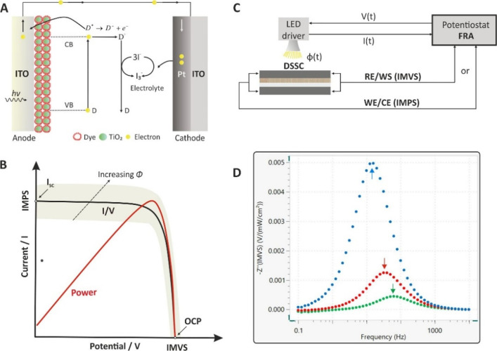
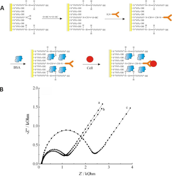
This tutorial provides the theoretical background, the principles, and applications of Electrochemical Impedance Spectroscopy (EIS) in various research and technological sectors. The text has been organized in 17 sections starting with basic knowledge on sinusoidal signals, complex numbers, phasor notation, and transfer functions, continuing with the definition of impedance in electrical circuits, the principles of EIS, the validation of the experimental data, their simulation to equivalent electrical circuits, and ending with practical considerations and selected examples on the utility of EIS to corrosion, energy related applications, and biosensing. A user interactive excel file showing the Nyquist and Bode plots of some model circuits is provided in the Supporting Information. This tutorial aspires to provide the essential background to graduate students working on EIS, as well as to endow the knowledge of senior researchers on various fields where EIS is involved. We also believe that the content of this tutorial will be a useful educational tool for EIS instructors.
Keywords: transfer function; frequency response analyzers; constant phase element; Warburg, reflective and transmissive diffusion; transmission line; porous electrode; metal corrosion; fuel cells; lithium-ion batteries; capacitive and impedimetric biosensors
1. Electrochemical Impedance Spectroscopy at a Glance
Electrochemical impedance spectroscopy (EIS) offers kinetic and mechanistic data of various electrochemical systems and is widely used in corrosion studies, semiconductor science, energy conversion and storage technologies, chemical sensing and biosensing, noninvasive diagnostics, etc. EIS is based on the perturbation of an electrochemical system in equilibrium or in steady state, via the application of a sinusoidal signal (ac voltage or ac current) over a wide range of frequencies and the monitoring of the sinusoidal response (current or voltage, respectively) of the system toward the applied perturbation. Considering that the electrochemical system under study is a linear time-invariant system (that is, the output signal is linearly related to the input signal and the behavior of the system is not changed over time), EIS is a “transfer function” technique that models the output signal (ac current or ac voltage) to the input signal (ac voltage or ac current) over a wide range of frequencies.
The importance of EIS over other electrochemical techniques lies in its ability to discriminate and, thus, to provide a wealth of information for various electrical, electrochemical, and physical processes take place in a real electrochemical system. This task is very challenging as all these different processes exhibit different (from very fast to very slow) time behaviors. The resistance of a liquid electrolyte, the different bulk and grain boundary conductivities when a solid polycrystalline electrolyte is employed, the charging/discharging of the electric double layer at the electrolyte/electrolyte interface, the dependence of the capacitive behavior of the electric double layer on the morphology of the electrode surface and the composition of the electrolyte, the kinetics of an electrode charge-transfer reaction, homogeneous reactions and adsorption/desorption phenomena coupled with the electrode charge-transfer reaction, mass transfer phenomena (diffusion of species to the electrode surface), etc., exhibit different time constants, τ, (a measure of the time behavior of a process). The time constant of a process is given as
| 1 |
where R is the resistance of a resistor in ohms and C is the capacitance of a capacitor in farad, F. Note that time constant is in time units in s. [(1 ohm) × (1 farad) = (1 V/1 A) × (1 coulomb/1 V) = 1 coulomb/ampere = 1 s].
Notably, EIS measurements at an electrochemical system can be simulated to an equivalent electrical circuit, which consists of common passive components (such as resistances, capacitors, and inductors) and others, more complicated (referred to as distributed) elements, connected each other in different ways. In other words, each of these processes can consequently be deemed analog to an equivalent electrical circuit that is characterized by a different time constant. For this purpose, most electrochemical analyzers are provided with suitable software enabling the simulation of the impedance data to a model circuit. Specialized equivalent circuit modeling software, such as Zview and Zplot (Scribner Associates, Inc.) is also available. A prerequisite for the simulation of the EIS data to an equivalent electric circuit is that the validity of the data has prior been evaluated. This can be done by running the so-called Kramers–Kronig test, which is available in most software provided with electrochemical analyzers. Considering that (i) there is not a unique model circuit for a given impedance spectrum and (ii) the quality of the modeling increases with the number of the components included in the circuit (the more the better), it is important that each component is correlated to an individual process by scientific logic.
When working in the time domain, as with one of the commonly used voltammetric techniques (cyclic voltammetry, a chrono technique, etc.), some of these processes is very difficult, if not impossible, to be analyzed. On the other hand, when working in the frequency domain, over a wide range of frequencies, EIS simplifies a complex electrochemical system by deconvoluting it in individual processes with different time constants, which then can be easily analyzed. (Very) slow processes can be probed in (very) low frequencies, while (very) fast processes can be probed in (very) high frequencies.
Practically, the frequency range is dictated by limitations associated with the available instrumentation, the wiring of the electrochemical system with the instrument (high frequency limit), and the stability of the electrochemical system itself over time (low frequency limit). The frequency range in most of the commercially available electrochemical analyzers spans from 10 μHz to 1 MHz. For more specialized applications, such as the study of ionic motion in polycrystalline solid ionic conductors, a very fast process with a very small time constant at the microseconds range,1 some vendors offer instruments enabling excitation frequencies at some MHz. On the other hand, in practical applications the lowest frequency limit is limited to 1 mHz (often, at 10–100 mHz) as the time required for a measurement to be conducted at these frequencies is very long (for example, at 10 μHz, a single measurement takes 1/10–5 Hz = 105 s = 27.8 h). Typically, an EIS spectrum containing measurements at 60 frequencies over the range from 100 kHz to 0.1 Hz (based on a logarithmic distribution, ten frequencies per decade) takes about 2–3 min.
A comprehensive paradigm on how to estimate the frequency range that is required for the EIS study of a typical electrochemical process including a faradaic reaction with a rotating disk electrode is given in refs (2 and 3). The response of this system to a certain perturbation (for example, the resulting ac current to a small amplitude ac voltage perturbation, typically superimposed over a dc voltage related with the formal potential Eo of the redox couple) is governed by three processes: the charging/discharging of the electric double layer at the electrode/electrolyte interface, the kinetics of the faradaic reaction, and the diffusion of the redox species from the bulk solution to the electrode surface. Each process exhibits a different time constant. According to the given set of data, the time constants, and the characteristic frequencies, shown in parentheses, for the charging/discharging of the electric double layer, the faradaic reaction and diffusion are 0.04 ms (4.1 kHz), 0.51 ms (310 Hz), and 0.41 s (0.4 Hz), respectively. Thus, for this specific example, the frequency range necessary to cover sufficiently the high and lower calculated frequencies can be from 10 kHz to 10 mHz.
It is noted, however, that in practice, the frequency range is not calculated but is selected in an experimental logic. Below we will see and explain in detail that in the most typical graph for the representation of impedance data, the so-called Nyquist plot, a time constant can ideally be visualized as a semicircle (most of the EIS textbook’s front pages illustrates Nyquist plots involving successive semicircles).
At the peak frequencies (fp) of these semicircles (the highest point of the arc) holds the equation
| 2 |
and so, it turns out that in order for the full semicircle to be seen, the (2πfp)τ ≫ 1 condition should be satisfied. By extension, well-separated semicircles representing different processes with different time constants, τx, τy, require that τx ≫ τy.
These unique capabilities have established EIS as a powerful and highly competitive technique for the study, optimization, and development of various real electrochemical cells in modern applications in corrosion science, fuel cells, lithium-ion batteries, photovoltaic cells, and (bio)sensing. This tutorial aims to acquaint the reader with the theoretical background, the principles, and the applications of EIS in various research and technological sectors. In this regard, the text has been organized to provide basic knowledge on sinusoidal signals, complex numbers, phasor notation, and transfer functions, to define the impedance in an electric circuit containing common passive elements and to introduce the principles of EIS along with key points in the validation of the experimental data and their simulation to equivalent electrical circuits. To this goal, a user interactive excel file containing some model circuits is provided in the Supporting Information. The user is allowed to change the values of the circuits’ components and to see how the respective Nyquist and (magnitude and phase) Bode plots are transformed. The following sections refer to the instrumentation related with impedance measurements (frequency response analyzers and accuracy contour plots) and the description of a real electrochemical cell. The main electrochemical processes (charging/discharging of the electric double layer, kinetic and mass transfer phenomena) take place in the absence and in the presence of a redox molecule in the measuring cell are explained in detail, and the Randles circuit is introduced. Simulated impedance plots of a Randles circuit for different values of the capacitance of the electrical double layer and of the charge-transfer resistance with respect to the different values of the heterogeneous transfer rate constant of a redox process are provided. The constant phase element, the Warburg impedance element at semi-infinite diffusion and reflective or transmissive boundary elements at finite length diffusion, and finally, the Gerischer element expressing the semi-infinite diffusion of a chemical-electrochemical (C–E) reaction are also presented. Simulated impedance plots for a rotating disk electrode experiment at different angular velocity values, of a reflective boundary element for increasing values of the diffusion related parameter, and of a C-E reaction at different reaction rate values are given. The impedimetric profile of a porous electrode with a transmission line is presented, while the inductive behavior in electrochemical cells and during impedance measurements, as well as additional practical considerations in conducting an EIS experiment are provided. The last part of the tutorial is devoted to the utility of EIS in corrosion, various energy related applications and biosensing, including lithium-ion batteries, solid oxide fuel cells, dye sensitized solar cells (IMVS and IMPS measurements), and capacitive and impedimetric biosensors.
As it is evident, EIS is a multidisciplinary subject which relies on at least basic knowledge of electric theory, mathematics, and electrochemistry. In this regard, the tutorial has been structured to include basics knowledge complementary to EIS and to generate a gradient evolution from these introductory topics to more in-depth analysis of EIS theory. Obviously, the understanding of these concepts requires the minimum mathematical knowledge that we have tried to instill in the reader.
Inevitably, the full comprehension of EIS theory requires a vastness of information that is impossible to fit solely in a tutorial article. For this reason, the reader is also advised to refer to textbooks on fundamental electrochemistry,4−6 to textbooks specialized to EIS1,3,7,8 other tutorials and review articles,2,9−12 fundamental papers,13−17 as well as to various application notes available in the Web sites of various vendors, such as Metrohm,18 Ametek,19 Biologic,20 Gamry,21 Zahner,22 Ivium,23 etc.
As a last note, we would like to encourage the readers to keep reading the text despite possibly coming across difficulties in the beginning, and to advise them not to rush to a section before they find the preceding sections fully understood.
2. Sinusoidal Signals
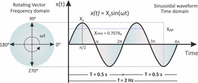
The instantaneous value of a sinusoidal signal, x(t), is given from the projection of a rotating vector of length Xo, that rotates anticlockwise with a constant angular frequency ω, at the cosine axis (perpendicular component) of a trigonometric circle as shown in Figure 1. Starting at t = 0, a complete revolution of 360° (ωt = 2π) will produce a sinusoidal waveform from 0 to 360° or 2π. At ωt = 90° = π/2 and ωt = 270° = 3π/2 the cosine component corresponds to its maximum values, (+Xo) and (−Xo), respectively. Thus, instantaneous values of the sinusoidal signal x are given by the equation
| 3 |
where ω is the angular frequency in rad/s and Xo is the signal amplitude.
Figure 1.
Representation of a vector rotating with a constant angular frequency ω and the corresponding sinusoidal signal, x(t) = Xo sin(ωt).
The Xo is also called as peak signal (Xp), and so, Xpp is the peak-to-peak signal which obviously is double to Xp (Xpp = 2Xp). With respect to the Xo, the effective signal or root-mean-square (rms) value of a sinusoidal signal is defined as
| 4 |
The rms value of a sinusoidal signal, for example current or voltage, corresponds to the value of the respective constant signal that if applied to an ohmic resistance would produce the same power (heating effect).
The time characteristics of the sinusoidal signal can be described from the frequency f (circles per one second) in Hertz, Hz, and the period Τ (the time that is required for a complete circle) in seconds, s, which connected each other and with the angular frequency with the equation
| 5 |
For example, if the period Τ of the sinusoidal signal illustrated in Figure 1 is 0.5 s, the frequency f will be 2. When we want to compare two sinusoidal signals of the same frequency, besides their magnitudes, we also need to consider the phase difference between them, if any. Figure 2 illustrates two sinusoidal signals, x(t) and y(t), of the same frequency and magnitude, Xo = Yo. We can see though that the instantaneous values x(t), y(t), differ because of the phase angle or phase shift (φ) between the two rotating vectors. For simplicity, we can assume one of these signals as the reference and thus the phase shift between them is expressed with respect to it. For example (Figure 2), instantaneous values of the sinusoidal signal y are given by the equation
| 6 |
The immobile vector, “fixed” at time t at a rotating angle ωt is called phasor and is represented with (∼). The phasor is a complex number that represents the amplitude and phase of a sinusoidal signal. In the example illustrated in Figure 2, the phase angle of phasor X̃, which is taken as reference, is zero, and the phase difference between the two phasors X̃ and Ỹ is φ. The two phasors are “out of phase” and the Ỹ phasor is said to be “lagging” (or conversely the X̃ phasor to be “leading”). If φ = 0, the two phasors are “in phase”, that is, they reach their maximum and minimum values at the same time.
Figure 2.
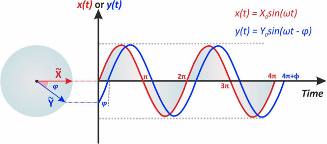
Phasor diagrams for the sinusoidal signals x(t) and y(t). The immobile vectors after a specific time correspond to the phasors X̃ and Ỹ and the phase difference between them.
3. Complex Numbers and Phasor Notation
A periodic or a sinusoidal signal can be expressed as complex number (z)
| 7 |
where the a is the real part on the x-axis, b is the imaginary part on the y-axis, and j the imaginary unit, j2 = −1. Note that both a and b are real numbers; just real numbers on the y-axis are multiplied by the imaginary unit. For the real and imaginary parts of a complex number z, symbols z′ or zr or Re{z} and z″ or zim or Im{z}, can also be used, respectively.
A complex number can also be expressed with respect to its magnitude, |z|, as
| 8 |
where
| 9 |
| 10 |
| 11 |
| 12 |
(note the difference between tan (φ), which is the tangent of angle (φ), and the tan–1or arctan, which gives the angle (φ) in radians that then can be converted to degrees), or, by using the Euler equation
| 13 |
in its exponential form as
| 14 |
The representation of a complex number on the complex plane and its analysis to its real and imaginary parts are shown in Figure 3A. Conversely, since phasor X̃ is a complex number, it can be expressed either with eqs 7, 8, and 14 or be represented on complex plane as shown in Figure 3B.
Figure 3.
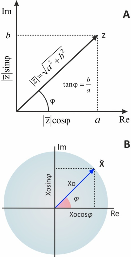
Representation of a (A) complex number z and a (B) phasor X̃ on the complex plane
Based on the Euler equation (eq 13) and eqs 9 and 10, ejφ is a complex number, the real and imaginary parts of which are cos(φ) and sin(φ), respectively. In this regard, the sinusoidal signal x(t), written in the cosine form
| 15 |
can be expressed as the real part of a complex number
| 16 |
and be represented, in phasor notation, as
| 17 |
where
| 18 |
As the angular frequency ω is constant, the term ejωt can be suppressed, and thus, the sinusoidal eq 6, from the time domain, can be expressed by a much simpler way, only by its magnitude and phase, by using phasors, at the frequency domain.
Accordingly, if the phase angle is zero or (−φ), in phasor notation, the respective sinusoidal signals can be expressed as X̃ = X0 and X̃ = X0e–jφ, respectively. We will see below that the expression of a sinusoidal signal in the frequency domain, by phasor notation, is very convenient to the analysis of a linear system signal response (output signal) to a sinusoidal input signal.
4. Transfer Function
An electrical, mechanical, or electrochemical system can be interrogated by applying to that an input signal x(t) to produce an output signal y(t). Considering that (i) the output signal is produced only after the interrogation of the system by the input signal, (ii) under specific experimental conditions, the input/output signals are related in a linear fashion, and (iii) the properties of the system remain constant with time, then the input–output relation for such a linear time-invariant (LTI) system can be modeled by a transfer function H, so that y(t) = H[x(t)] (Figure 4).
Figure 4.
Schematic representation of a linear time-invariant (LTI) system with an input sinusoidal signal x(t) at a frequency ω and the output sinusoidal signal y(t) at the same frequency. The input/output signals are related with the transfer function H(ω).
If the input signal is sinusoidal
| 19 |
with a small amplitude Xo that nonlinear effects can be neglected, the resulting output signal
| 20 |
will also be sinusoidal of the same frequency, shifted by the angle φ with respect of the input signal, which is taken as reference. The transfer function for this LTI system is a complex number at the frequency domain and can be defined as the ratio of the respective phasors, X̃ = Xo and Ỹ = Yoejφ or the various forms apply for a complex number (eqs 7, 8, 14) as
| 21 |
where |H| = Yo/Xo is the magnitude.
Even though both the input/output signals are in the time domain, the transfer function H(ω) is a function of frequency and does not depend on either the time or the amplitude of the input signal.2,3 Examples of various transfer functions are given in Table 1. In this tutorial, we will focus mostly on the impedance transfer function, while other important transfer functions for the study of photovoltaic cells, based on intensity modulated photocurrent spectroscopy (IMPS) and intensity modulated photovoltage spectroscopy (IMVS), are discussed in section 17.3.
Table 1. Various Transfer Functions (TF).
| transfer function | input signal | output signal |
|---|---|---|
| impedancea | voltage (V) or current (I) | current (I) or voltage (V) |
| IMPS24 | light intensity (φ) | photocurrent (I) |
| IMVS24 | light intensity (φ) | photovoltage (V) |
| electrohydrodynamic impedance25 | rotation speed (Ω) | current (I) or voltage (V) |
| thermoelectrochemical TF26,27 | electrode temperature (T) | current (I) |
| pneumatochemical impedance spectroscopy28 | pressure (P) | voltage (V) |
When the input signal is voltage (V), measurements correspond to admittance (see below), the inverse of impedance.
5. The Impedance of an Electrical Circuit
Impedance represents the total opposition to the current flow in an electrical circuit composed of resistors (R), capacitors (C), and inductors (L). Depending on the different passive elements (R, C, L) included in the electrical circuit under test and the way they are connected with each other, the impedance of the electrical circuit will differ. If we assume that a low amplitude alternating voltage at a particular frequency
| 22 |
is applied to the electrical circuit and the resulting alternating current at the same frequency
| 23 |
is measured, the impedance of the circuit at this frequency Z(ω), based on eq 21, is defined as
| 24 |
where Z′ is the real part representing resistance on the x-axis and Z″ is the imaginary part representing reactance on the y-axis, |Z|, the module of impedance, and φ = ωt, is the phase. With respect to eqs 9–12, the following equations are held:
| 25 |
| 26 |
| 27 |
| 28 |
It should be noted that despite its complex nature, the equivalent impedance of circuit elements in series, still follow Kirchhoff’s rule, is
| 29 |
while the impedance of circuit elements in parallel is
| 30 |
In those cases, it is often advantageous to the use the admittance, which is the inverse parameter of impedance (Y = 1/Z), where the equivalent admittance of circuit elements in parallel is
| 31 |
Admittance itself is a complex number that can be expressed as the complex equivalent of conductivity. When written in an algebraic form, it can be defined as
| 32 |
where G is called conductance (the inverse parameter of resistance) and B is called susceptance (the inverse parameter of reactance), (see section 6). In correlation with the corresponding impedance parameters, when the imaginary part is positive it is called capacitive susceptance (BC), and when it is negative, it is called inductive susceptance (BL).
We will see below that when the measurements of impedance are conducted over a wide range of excitation frequencies in order to produce the impedance spectrum, that is, an Electrochemical Impedance Spectroscopy experiment, impedance values are determined by the orthogonality of sines and cosines method, which is compatible with the operation of the frequency response analyzers (FRA) (see section 9) that are commonly used in such measurements. Before that, however, it is important to examine the behavior of the major passive components (R, C, L) in dc circuits (f = 0) and ac circuits (f ≠ 0), in order to understand why an impedance spectrum can provide data for analyzing an electrical circuit, and by extension, a real electrochemical cell.
6. Resistance and Reactance
In dc circuits the current flow is impeded only by resistors. This opposition is called resistance, which is given by Ohm’s law as the quote of the applied constant voltage V in volt, V, and the resulting constant current i in ampere, A, flows through a resistor.
| 33 |
Constant current does not flow through a capacitor. However, depending on the applied constant voltage the capacitor stores an amount of electrical charge (q), which equals the product of the applied potential and its capacitance (capacitance C in farad, F) according to the equation:
| 34 |
The voltage across an inductor of inductance L, in henry, H, is given by equation
| 35 |
For a constant current, di/dt = 0, the voltage across its terminal is zero, and thus, the current flows thought it without any resistance.
In ac circuits on the other hand, the current flow is also impeded by capacitors and inductors. This opposition is called reactance, denoted as XC and XL, respectively, and measured also in Ohm. The voltage/current time characteristics and the equations of impedance at each of these passive components is given below.
As can be seen in Figure 5A, when an ac voltage is applied to a resistor, the resulting ac current follows the ac voltage without delay. The sinusoidal waveforms v(t) and i(t) are in-phase (φ = 0), and thus ejφ = 1, sin(φ) = 0 (eq 21). As a result, the impedance in this case is independent of the frequency and contains only the real component:
| 36 |
Figure 5.
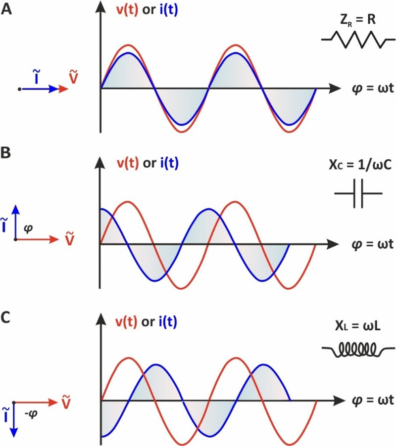
(Left) phasor diagrams and (right) the respective sinusoidal waveforms v(t) and i(t) when a low amplitude alternating voltage is applied to (A) a resistor, (B) a capacitor, and (C) an inductor.
If an ac voltage, v(t) = Vo sin(ωt), is applied to a capacitor C, the resulting ac current flowing in the circuit, as a result of the fluctuation of the electrical charge stored in the capacitor, is given as29
| 37 |
The solution of the differential eq 37 gives
| 38 |
By combining eqs 37 and 38, one gets
| 39 |
For ωt = π/2, the magnitude of the current is
| 40 |
and the reactance is given as
| 41 |
eq 41 shows that XC is inversely proportional to the frequency and capacitance. The eq 39 can also be written as
| 42 |
showing that the voltage applied to the capacitor lags the current by 90° as it also illustrated by the respective sinusoidal waveforms in Figure 5B. According to the eq 21, for φ = 90°, the real part of impedance is zero. In a similar way can be found that when the circuit contains only an inductor, inductive reactance XL is given by equation
| 43 |
indicating that XL increases at higher frequencies. As can be seen in Figure 5C, the voltage and current waveforms are also “out-phase”, however, in this case, the voltage is leading the current by 90° (the real part of impedance is also zero).
The different properties of ZR, XC, and XL in ac circuits (ZR, contains only a real component and is independent of the frequency, XC contains only an imaginary component and decreases upon the increase of frequency, while XL that also contains the imaginary part only, is increasing upon the increase of the excitation frequency) provide us the possibility, by measuring the impedance of a complex electrical circuit over a wide range of excitation frequencies, to discriminate the response of the individual passive elements.
7. Electrochemical Impedance Spectroscopy
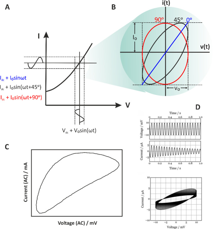
EIS technique relies to the application of a small-amplitude stimulus (voltage or current), usually superimposed on a dc signal (voltage or current) to an electrochemical system and measurement of the resulting response (current or voltage, respectively) over a wide range of frequencies. It is essential that measurements are conducted by applying a small-amplitude perturbation in order to ensure a linear relationship between the applied signal and the response of the system. However, as can be seen in Figure 6A, the current–voltage relationship in real electrochemical cells is not linear. Measurements at a linear domain can sufficiently be approximated only by using a small-amplitude perturbation signal. Most of the available software in modern electrochemical analyzers provides at real time during the impedimetric measurements the so-called Lissajous plots that display the alternating voltage at the x-axis and the alternating current at the y-axis signals over time (Figure 6B). Depending on the magnitude of the signals and the phase difference between them, a typical oval plot is obtained. It turns out that when the phase difference is 0° or 90°, the plot appears as a diagonal or circle, respectively. The symmetry and the motion of the Lissajous plot over time indicate whether the electrochemical system conforms to the constrain of linearity (for nonlinear systems the shape of the plot is distorted)30 and time-invariance (when the system is stable over time, the plot is immobile).31 To highlight the difference in the Lissajous plots in the cases mentioned above, Figure 6C shows a nonlinear Lissajous plot with an apparent distorted shape, while Figure 6D shows an unstable Lissajous plot where the amplitude of the current response decreases over time.
Figure 6.
(A) Schematic representation of an electrochemical system’s response to a low-amplitude (Vo) sinusoidal signal superimposed to a constant voltage Vdc and (B) the respective Lissajous plots if we consider that the phase shift between the perturbating and response alternating signals is 0°, 45°, or 90°. (C) A Lissajous plot showing a nonlinear response. Courtesy of Metrohm Autolab B.V.30 (D) Lissajous plots of a system interrogated with an ac voltage with amplitude ±10 mV, at 20 Hz, where the amplitude of the current response decreases with time. Reprinted in part with permission from ref (31). Copyright 2021 Wiley.
The validity of the impedimetric data can be further evaluated by using the Kramers–Kronig relations. The Kramers–Kronig relations enable the calculation of the real part of the impedance from the imaginary part, and vice versa by using the following equations
| 44 |
| 45 |
The interdependence between the real and imaginary parts of impedance is the essential element of this transformation. These relations allow the detection of various errors present in impedance measurements of an electrochemical system. In general, their satisfaction is depended by four different criteria:
7.1. Linearity
The system under investigation should be linear. In other words, the input and output signals should involve the same frequency. However, as mentioned above most electrochemical systems tend to exhibit nonlinear behavior, unless small amplitude perturbation signals are used.
Experimental Advice
Impedance measurements at different small-amplitude perturbation signals should yield identical results, since the impedance of linear systems is independent of the amplitude used.
7.2. Causality
This condition implies an exclusive cause-to-effect relationship between the input signal and the response of the system. In other words, system’s response should be entirely dependent on the applied perturbation.
7.3. Stability
A stable system is stable until excited by an external stimulus and should be able to return to its original state when the perturbation stops.
Experimental Advice
Repetitive recording of the impedance spectra must yield identical results.
7.4. Finiteness
The real and the imaginary components of the system must have finite values over the entire frequency range 0 < ω < ∞. This also means that the impedance must tend to a constant value when ω → 0 or ω → ∞.
Kramers–Kronig transformations can detect errors in the impedance spectrum of an electrochemical system, through data integration over the entire frequency range, which is admittedly experimentally impossible. For this reason, a number of approximations have been developed to assess the Kramers–Kronig compliance of an impedance spectrum. Boukamp32,33 proposed fitting of the impedance spectrum with a Voigt circuit (n(RC)) with a fixed distribution of time constants to approximate the behavior of real electrochemical systems. If a system is well approximated by this circuit, then it is considered to be Kramers–Kronig transformable.
Once the impedimetric data have been received and validated, they can be analyzed by plotting them in different formats, among others, such as −Z″ = f(Z′), Z′ = f(ωZ″), Y″ = f(Y′), Z″/ω = f(Y′/ω), Z′, −Z″ = f(f), log|Z|, −phase = f(log f), Z′, – Z″ = f[sqrt(ω)], etc. These graphs can be easily constructed by the software of the electrochemical analyzers by using the data have been collected by a single experiment, thus providing a flexible tool to retrieve a plethora of information for the components of the examined electrochemical system. The most widely used formats are the Nyquist and Bode plots.
In the Nyquist plot, −Z″ = f(Z′), the imaginary part of the impedance, usually as −Z″, is plotted versus the real part of impedance, Z′, at each excitation frequency. As a rule, in a Nyquist diagram the two axes should be of the same range; however, very often, incorrectly, for reasons of clarity in the presentation of spectra, the data in y-axis are zoomed in. The presentation of the impedance spectra as Nyquist plots has two major disadvantages: (a) the nondistinct display of the spectrum in the high-frequency range, since the large impedance values in the low-frequency range determine the scale of the axes and (b) the lack of direct frequency-impedance matching.
The Bode plot shows two curves: the log|Z| = f(log f), and the −phase = f(log f), thereby providing an easy matching of the excitation frequency with the module of impedance and the phase values. In addition, since |Z| and frequency data are presented in a logarithmic scale, impedance data over a wide range of frequencies is clear. Also, the use of the Bode plot is convenient when the spectrum includes scattered values. Of course, the validity of these values should be checked, as indicated above, and should be removed, if found invalid.
8. Simulation of Impedance Data to Model Electrical Circuits
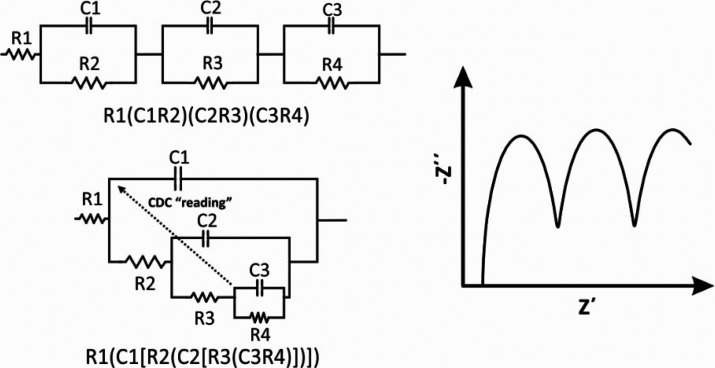
As mentioned above, a great advantage of EIS is the simulation of the data (an impedance spectrum) to an equivalent electrical circuit and in this way to retrieve numerical values for the components included in the circuit. For this purpose, one can use the software that comes with the frequency response analyzers, or more dedicated software, such as Zview, Zplot, and others. The quality of the data modeling to a specific equivalent electrical circuit is defined by the chi-square (x2) value (see section 16). It is noted however that there is not a unique model circuit for a given impedance spectrum. The simulation of an impedance spectrum with more than one circuit is possible, as some circuits are mathematically identical. An example is illustrated in Figure 7. In this case, the selection of the most appropriate circuit requires a deep knowledge of the electrochemical system.
Figure 7.
Examples of different electrical circuits that generate identical impedance spectra.
Electrical circuits can be denoted by using the “circuit description code” (CDC) proposed by Boukamp.34 The simplest case where single elements are connected in series, for example a resistor and a capacitor, the circuit is denoted as RC. When single elements are connected in parallel are enclosed in parentheses. For example, a parallel connection between a resistor and a capacitor is denoted as (RC). It follows that at a circuit, in which the “(RC)” complex element is connected in series with a resistor, the circuit is denoted as R(RC). In a more complex circuit in which the complex “R(RC)” element is connected in parallel with a resistor, the complex element “R(RC)” is enclosed in square brackets, [R(RC)], and the circuit is denoted as (R[R(RC)]). Examples of two more complex circuits, designated as R1(C1R2)(C2R3)(C3R4) and R1(C1[R2(C2[R3(C3R4)])]), are given in Figure 7.
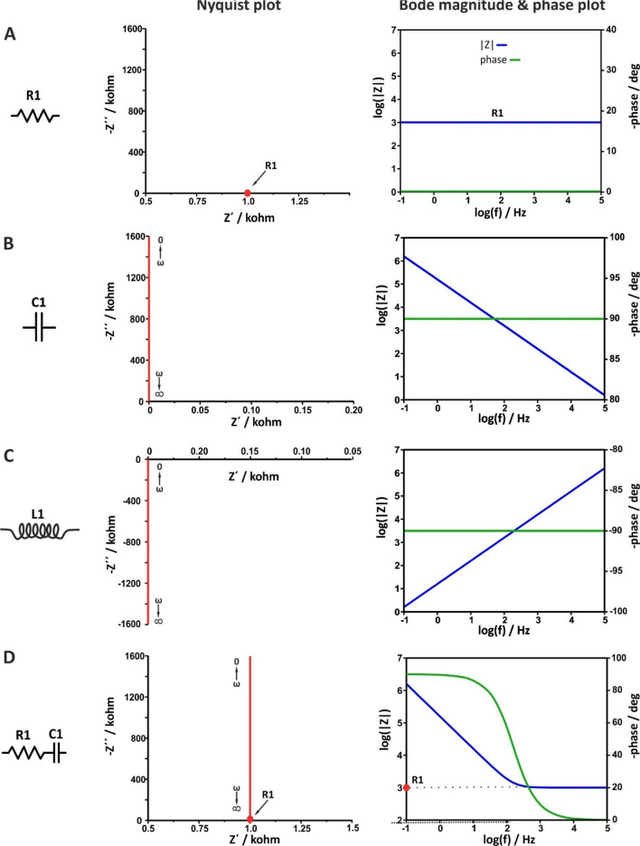
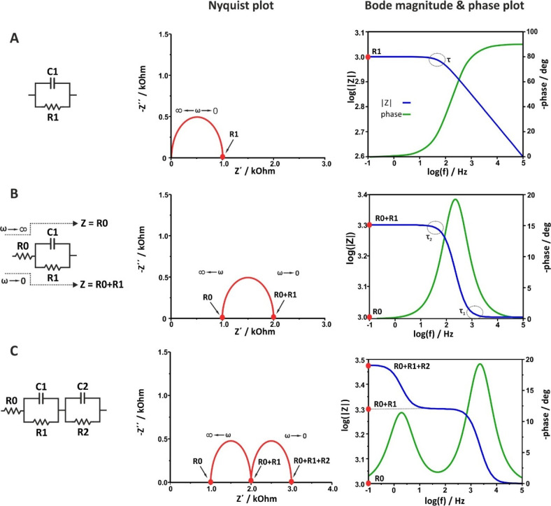
The Nyquist and Bode plots for various simple electrical circuits containing a single passive element (R, C, or L) as well as combinations of them in different arrangements (in series or in parallel) are illustrated in Figure 8 and Figure 9, respectively.
Figure 8.
Nyquist, Bode magnitude and phase angle plots of some model circuits. R1 = 1 kOhm.
Figure 9.
Nyquist, Bode magnitude, and phase angle plots of some model circuits. R0 = R1 = R2 = 1 kOhm.
When the circuit contains only a resistor, Figure 8A, the equation of the impedance is Z = R + j0. The real part equals R, while the imaginary part is zero. As a result, the Nyquist plot shows a single point lying in the real axis. That is, the impedance values at all the excitation frequencies are exactly the same and equal to the value of the resistance of the resistor (in this example, R1 = 1 kOhm). As a result, the Bode magnitude plot shows a straight line that crosses the left axis at |Z| = R1, as
| 46 |
while the Bode phase angle plot shows a straight line that crosses the right axis at φ = 0°, as in accordance with Figure 5A, through a resistor, the voltage and current waveforms are “in-phase”.
When the circuit contains only a capacitor, Figure 8B, the equation of the impedance is Z = 0 + 1/jωC = 0 – j(1/ωC). The real part is zero, while the imaginary part is reversely proportional to the capacitance and frequency. As a result, the Nyquist plot shows a straight line lies in y-axis (the real impedance is zero). Values close to zero corresponds to high frequencies, while at lower frequencies the impedance values are higher. The Bode magnitude plot shows a straight line with slope −1, while the Bode phase angle plot shows a straight line that crosses the right axis at φ = −90°, as in accordance with Figure 5B, through a capacitor, the voltage and current waveforms are “out-of-phase” with π/2. Note that in real electrochemical cells the phase between voltage and current due to a “capacitive” element is typically lower than π/2. In this case, the impedimetric data can be sufficiently modeled only if instead of an ideal capacitor (C), the so-called constant phase element (CPE) is used (see section 12).
When the circuit contains only an inductor, Figure 8C, the equation of the impedance is Z = 0 + jωL. The real part is zero, while the imaginary part is proportional to the inductance of the coil and frequency. As a result, the Nyquist plot shows a straight line lies in y-axis, below the real axis, as in this case the phase difference between voltage and current is φ = 90°. Values close to zero corresponds to low frequencies, while at higher frequencies the impedance values become higher. The Bode magnitude plot shows a straight line parallel to the frequency axis. At all the measurements the phase difference is 90°, in accordance with Figure 5C where the voltage leading the current π/2.
When the circuit contains a resistor and a capacitor connected in series, Figure 8D, the equation of the impedance is
| 47 |
In this case, the real part is Z′ = R1 and the imaginary part is Z″ = 1/ωC1. Note that the pattern of the Nyquist plot is a combination of the Nyquist plots described above when the circuit contains only a resistor, Figure 8A, or only a capacitor, Figure 8B.
The Bode magnitude plot shows, at high frequencies, a straight line parallel to x-axis the extension of which crosses the axis of the impedance modulus at |Z| = R1 (that is, the response is dominated by the resistance and thus is independent of the frequency). At lower frequencies, the imaginary part increases, at a specific frequency, ω = 1/R1C, equals the real part, while at even lower frequencies, the response is dominated by the imaginary part. This transition is shown at the Bode phase plot as an S-shaped curve leveling, at high frequencies, at φ = 0ο and, at very low frequencies, at φ = −90ο.
When the circuit contains a resistor and a capacitor connected in parallel, Figure 9A, the equation of the impedance is
| 48 |
and the Nyquist plot corresponds to a semicircle.
In this case, at very high frequencies the capacitive reactance tends
to zero (ω → ∞, Xc → 0), and thus, all the current passes through the capacitor.
The circuit acts as a short circuit and the impedance is zero. At
very low frequencies, the capacitive reactance tends to infinity (ω
→ 0, Xc →
∞), and all the current passes through the resistor. The impedance
contains only real part and Z′ = R1. In response to the discussion above, when the ω →
0 the current is constant. The constant current cannot flow through
the capacitor, it flows only though the resistor. At intermediate
frequencies, the current passes at the same time through the capacitor
and the resistor, while the ratio of the respective currents is defined
by the opposition of the current flow through each branch. Traversing
from high to medium frequencies, the capacitive reactance becomes
larger (see eq 41) but
remains still lower than the ohmic resistance (Xc < R1), which causes more alternating current to go through
the capacitor while less constant current goes through the resistor.
However, there is a single characteristic frequency corresponding
to equal values of reactance and resistance (Xc = R1). At this frequency the imaginary part of the impedance
is maximum (ωZmax″). By substituting Xc with R1, in eq 41, we get that  , and consequently
| 49 |
where τ = R1C1 is the characteristic
time constant of the system. Note that by substituting  to eq 48, it becomes
  , thus manifesting that in a RC parallel
circuit, and τ is found when the imaginary and real part of
the impedance are equal.
Looking at the Bode magnitude plot,
according to the eqs 46 and 48,
at very low frequencies, |Z| = R1, while at very
high frequencies  The slope of the curve is changing (this
breaking point is highlighted in Figure 9A with a dotted-line circle) around the frequency
that corresponds to the time constant of the system.
If a resistor R0 is connected in series with the circuit in Figure 9A, the equation of the impedance for the resulting circuit (Figure 9B), denoted as R0(R1C1), will be
| 50 |
At both very high and very low frequencies,
the behavior of the circuit is resistive and thus the semicircle is
shifted to the real axis to a value equal to the ohmic resistance
of R0. As indicated in Figure 9B, at very high frequencies, (ω → ∞; XC → 0), Z = R0, while
at very low frequencies (ω → 0; XC → ∞), Z = R0 + R1. These boundaries
conditions are illustrated in the Nyquist plot as the first and the
second crossing points of the semicircle on the axis of the real impedance,
respectively. In contrast with the previous circuit (Figure 9A), this circuit has two time
constants indicating the two breaking points appear at the Bode magnitude
plot. The τ1 at the high frequency domain is influenced
by R0 and can be calculated as τ1 = [(R0R1)/(R0 +
R1)]C1. The τ2, at lower frequencies, which as the
slowest one is considered as the characteristic time constant of the
system, can be calculated from the Nyquist plot as in the case of
the simple RC parallel circuit, as  . Looking at the Bode plot of this circuit,
the change of |Z| and phase over a wide frequency
range is described by an S-shaped and a bell-shaped curve, respectively.
If the circuit in Figure 9B is connected in series with a second parallel (R2C2) circuit, the circuit in Figure 9C, denoted as R0(R1C1)(R2C2), will occur. The equation of the impedance for this circuit is
| 51 |
Similar to the above analysis, this circuit exhibits two characteristic time constants, τ1 and τ2, corresponding to the ωZmax″ at each semicircle. Depending on the ratio of τ1 and τ2 values, the Nyquist plot displays two well-resolved (τ1 ≫ 100τ2) or poorly resolved (τ1 < 100τ2) semicircles, while when τ1 = τ2 a single semicircle is appeared. The ratio between the τ1 and τ2 values also shapes the pattern of the Bode magnitude and phase plots. When τ1 ≫ 100τ2, the second time constant results in the inclusion of a second step and peak, in the resulting plots, respectively.
8.1. Tutorial Material
A user interactive excel file containing eight different model circuits is provided in the Supporting Information. The user is allowed to change the values of the circuits’ components and to see how the respective Nyquist and (magnitude and phase) Bode plots are transformed.
9. Frequency Response Analyzers and Contour Plots
As mentioned above, an EIS experiment involving the measurement of the impedance of the cell under study after its excitation with a small-amplitude sinusoidal perturbation signal (for example, voltage) at several excitation frequencies, usually over the range from some mHz to 1 MHz. Even though for many applications excitation frequencies up to 100 kHz are sufficient, in applications involve solid electrolytes, the full resolution of the impedimetric behavior at the high frequency range requires measurements to be conducted up to some MHz. Depending on the application, the sinusoidal perturbation signal is usually superimposed over a dc signal, such as the open circuit potential (OPC) at which the current flowing in the cell is zero, or the formal potential of a redox probe, for example in faradaic EIS experiments in various biosensing applications.
Nowadays, several vendors offer electrochemical analyzers that comprise of a potentiostat-galvanostat and a FRA. The potentiostat ensures the application of a dc voltage (or current by the galvanostat), while the FRA ensures the application of the sine-wave perturbation signal to the cell and the analysis of the response into its real and imaginary components.
A simplified schematic of a potentiostat-FRA apparatus for a potentiostatic EIS experiment is illustrated in Figure 10. FRA determines the impedance of the cell under study by correlating the sinusoidal response, in this case i(t), with two synchronous reference signals, one that is in-phase [sin (ωt)] and a second one that is out-of-phase by 90° [cos(ωt)] with the sinusoidal voltage perturbation.11,35
Figure 10.
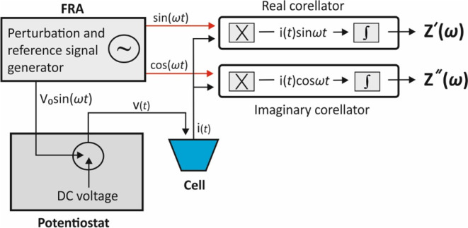
Simplified experimental setup for potentiostatic EIS and working principle of a frequency response analyzer. “X”, stands for multipliers and “∫” for integrators.
In specific, the generator produces a sinusoidal voltage excitation signal at a particular frequency, Vo sin(ωt), which is applied to the cell and the real part correlator at the same time (the voltage excitation signal is usually superimposed over a dc voltage signal and applied to the cell via the potentiostat). The generator also produces a second waveform, [cos(ωt)], which is out-of-phase by 90° with the excitation waveform, that is driven to the imaginary part correlator. The cell response i(t) is fed into both correlators and multiplied with the generated waveform. The signals are then driven to the integrators which remove all harmonic responses effectively except from the fundamental, and both the real and the imaginary components of the impedance are calculated. This process is repeated at various frequencies set by the user and the impedance spectrum is constructed. For more details, the reader is referred to refs (11 and 35). The real and the imaginary components of the impedance are given by the following equations
| 52 |
| 53 |
where NT is the number of periods over which the integration of the signal is performed. At the cost of a prolonged measurement time, which may impart the stability of the electrochemical system, when the number of the periods increases, the integration of the signal results in a more effective removal of noise to the response signal.
The accuracy of the impedance measurements for a given potentiostat/galvanostat FRA analyzer are illustrated in the so-called accuracy contour plot (ACP). A typical ACP for potentiostatic modulation is illustrated in Figure 11. ACP maps areas labeled with numbers indicating the maximum percentage error in impedance measurements and maximum error in phase angle readings within these areas (errors’ values in Figure 11 are given as an example). When measurements result in higher or lower impedance values or when impedance measurements are conducted at higher excitation frequencies, the errors are higher.
Figure 11.
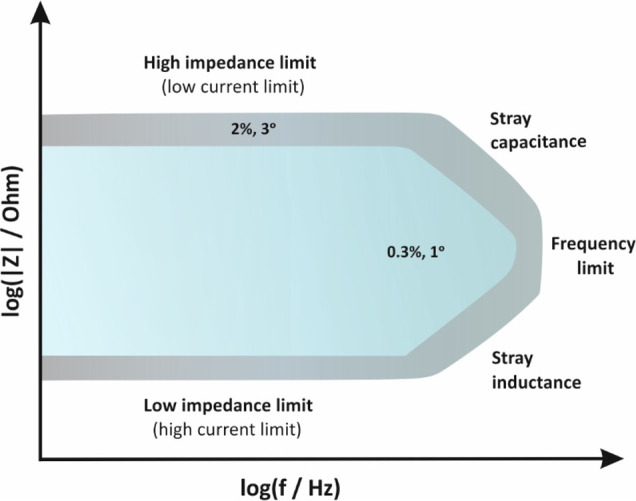
Accuracy contour plot indicating that within the blue area and under specific experimental conditions, impedance and phase angle readings are recorded with a maximum error 0.3% and 1°, respectively. Outside this area and within the gray area, the errors increase up to 2% and 3°, respectively. Errors’ values are given as an example.
In order to compare the accuracy of two different instruments, ACPs should be constructed under the same experimental conditions. Measurements are conducted at an amplitude lower than 10 mV rms, by using the instrument’s complementary cables, and by placing the cell under test in a Faraday cage. Under other conditions, that is, without using a Faraday cage and/or by using longer cables or cables which are not properly shielded, the results will differ (see section 16). Note that the high and low limits of the impedance measurements indicated in the ACP in the y-axis are not those correspond to open- (when the cables are not connected) or short- (when the cables are connected with each other) lead measurements, respectively. Under these conditions, impedance limits are much higher and lower, respectively; however, the accuracy of the measurements is very poor.36−39
At high frequencies, the accuracy of impedance measurements is dictated by cabling effects. In specific, the capacitance of the cables (which depends on the shielding quality) defines the upper limit, while their inductance (which depends on their length) define the lower limit of the measurable impedance.
At low frequencies, the accuracy of impedance measurements is dictated by hardware limitations. The upper impedance limit at low frequencies is associated with the lowest current that the potentiostat can measure in the sense that for a certain voltage perturbation at a high impedance cell (for example, at dielectric coatings) the resulting current will be very low. For this purpose, some electrochemical analyzers offer models or modules that enable measuring currents at the pA level (normally, the lowest measuring current is a few nA). On the other hand, the low impedance limit at low frequencies refers mostly to galvanostatic measurements at low impedance cells (for example, batteries and supercapacitors). At these low impedance cells, high currents are needed to cause a measurable voltage signal, since it is easier to measure μV ac signals than to control them. For this purpose, impedance measurements under these conditions are preferably conducted with instruments equipped with current boosters.
10. The Electrochemical Cell
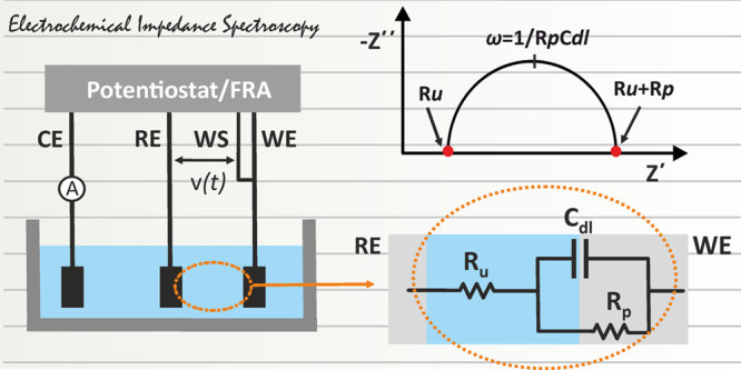
The most common electrochemical setup refers to a 3-electrode configuration consisting of the working electrode (WE), the reference electrode (RE), and the counter electrode (CE) in connection with a potentiostat. The working electrode offers the electrocatalytic surface on which a redox reaction takes place under a desirable potential, or in other words, under a desirable potential difference with respect to the (stable) potential of the reference electrode. If no current flows through it, the potential of the reference electrode is stable. The potentiostat measures the potential difference between the working and the reference electrode and corrects any deviation from the desirable value (the value set by the user) by circulating a current between the working and the counter electrodes. To ensure that all the current passes through the counter electrode, its surface is usually larger compared with that of the working electrode. Each of these electrodes are connected with the potentiostat with the appropriate current carrying (WE, CE) or voltage measure (RE) leads (terminals). The lead which carries current is also called force lead, while the lead that measures voltage, is also called sense lead. Modern electrochemical analyzers are 4-terminal devices incorporated with an extra sense lead, the working sense (WS) lead, which is usually sorted to the WE and is used for a more accurate measurement of the applied voltage to the electrochemical cell.
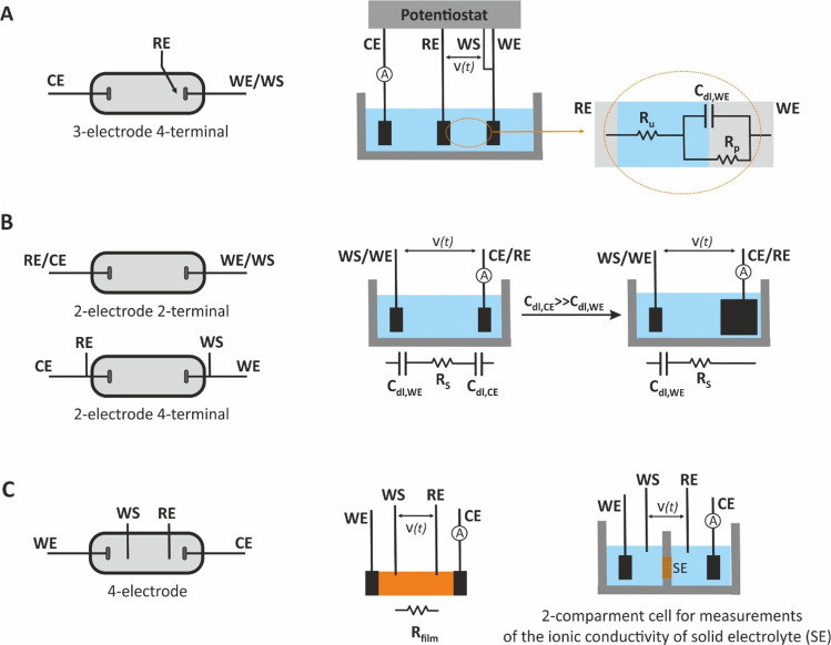
Besides the 3-electrode cell, other cells of 2-electrodes (such as the batteries, fuel cells or the interdigitated electrodes) or 4-electrodes also exist (Figure 12). At a 2-electrode cell, the reference sense lead is connected to the counter electrode (in a 2-electrode cell is named auxiliary electrode), which thus plays a dual role; It is used for both the application of the voltage and the current measurement. As a result, in 2-electrode cells, the potential of the WE cannot be precisely controlled. Depending on the way the electrodes are connected with the terminals of the potentiostat, the impedance of a particular area in the cell can be measured. This area is defined between the electrodes at which the voltage is applied.
Figure 12.
Different types of electrochemical cells of 2-, 3-, and 4-electrodes and different connection modes with the working (WE), working sense (WS), counter (CE), and reference (RE) electrodes.
In a 3-electrode, 4-terminal, setup (Figure 12A) the voltage is applied between the working and the reference electrodes. In this setup, under a small amplitude voltage perturbation, the impedance to the current flow, is due to (i) the ohmic resistance of the electrolyte between the reference and the working electrode, which is called uncompensated resistance (Ru). For a given electrolyte, Ru is defined by the distance between the reference and the working electrodes. In practice, this ohmic resistance also includes the ohmic resistance of the connection cables and the ohmic resistance of the working electrode, which in most cases can be neglected, (ii) the charging/discharging of the electric double layer; under ac conditions the electrical double layer at the electrode/electrolyte interface behaves as a capacitor and is symbolized as Cdl, and (iii) the polarization resistance Rp, which is defined as the slope of the voltage/current curve Rp = ΔV/Δi, at steady-state measurements. In EIS, steady-state conditions are approximated when the frequency tends to zero (f → 0). The equivalent electrical circuit of the cell is shown at an enlarger scale in Figure 12A. If we consider that the WE is an ideally polarizable electrode, then the charge transfer between the electrode and the electrolyte is not possible or it takes place in an infinitesimal rate and thus, the polarization resistance is infinite. In this case, all the current passes through Ru and Cdl and the impedance of the cell can be simulated to an electrical circuit in which Ru and Cdl are connected in series.
In a 2-electrode, 2-terminal setup, Figure 12B, the voltage is applied between the working and the counter (auxiliary) electrodes. Considering that both electrodes are ideally polarizable, the impedance to the current flow is due to the Cdl of each electrode and the ohmic resistance of the measuring solution Rs (in the absence of RE, the term Ru cannot be used) and the impedance of the cell can be simulated to an electrical circuit in which Rs, Cdl,WE, and Cdl,CE are connected in series. As the total capacitance (Ctot) of the cell is given by
| 54 |
Cdl,CE can be neglected if the surface of CE is considerable higher compared with that of WE.
In accordance with the discussion above, the measurable impedance of the 2-electrode, 2-terminal setup in Figure 12B, also includes the impedance due to the ohmic resistance of the wires. In some low impedance 2-electrode cells, such as batteries, the ohmic resistance of the wires cannot be neglected, and thus impedance measurements at a 2-electrode, 4-terminal mode is suggested. An example demonstrating the difference of the measurable impedance in each case is given in section 16.
In a 4-electrode (or 4-terminal) setup, Figure 12C, an ac current perturbation (galvanostatic measurements) is applied between the WE and CE, while the potential difference between RE and WS, due to the impedance of the sample, is measured. These measurements are quite common for measuring the conductivity of a thin polymer film or solid electrolytes.
11. Faradaic EIS—The Randles Circuit
The term faradaic EIS is used when the impedance of an electrochemical cell (for example, a 3-electrode 4-terminal setup in potentiostatic mode) is measured in the presence of a redox couple (Ox/Red) by applying a small sinusoidal voltage perturbation superimposed on a dc potential which matches the standard potential E° of the redox reaction
| 55 |
In this case, the total current which passes through the Ru is divided into the current related with the charging/discharging of the electrical double layer, iC, and the current related to the faradaic process, iF. At the equivalent electrical circuit illustrated in Figure 13A, the faradaic process is represented as a general impedance, ZF, which accounts for both the kinetics of the redox reaction and the diffusion of the redox species to the surface of the working electrode. In this regard, ZF can be divided into two components:
| 56 |
-
(i)the charge-transfer resistance, Rct, which is related with the kinetics of the heterogeneous electrochemical process assuming that the redox species are not absorbed on the electrode surface, as per equation
where k0 is the heterogeneous electron transfer rate in cm s–1, n is the number of electrons transferred in the electrochemical reaction, F is Faraday’s constant (96485 C mol–1), R is the gas constant (8.314 J mol–1 K–1), T is the temperature (K), A is the electroactive surface area of the working electrode in cm2, and C is the concentration of the redox species assuming that this concentration is the same as the one in the bulk solution and that Cox = CRed = C.
57 -
(ii)the so-called, Warburg impedance, ZW, which expresses the difficulty of mass transport of the redox species to the electrode surface considering a semi-infinite linear diffusion. ZW behaves as an RW – CW circuit in series, where both RW and CW are frequency dependent, and thus, the ZW can be written as4,7,16
where
58
D is the diffusion coefficient (cm2 s–1) of the redox couple assuming that DOX = DRED = D, while the rest of the symbols have their aforementioned meaning.
59
Figure 13.
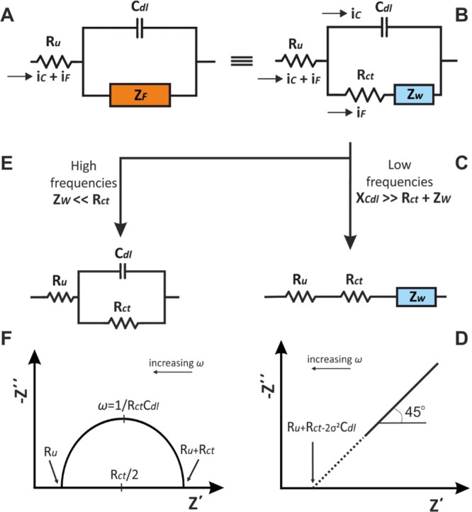
(A, B) The Randles equivalent circuit and its behavior at (C, D) low and (E, F) high frequencies. Adapted with permission from ref (4). Copyright 2022 Wiley.
The equivalent electrical circuit involving the charge-transfer resistance, Rct and the Warburg impedance, ZW, (Figure 13B) is the most common representation of the so-called Randles circuit.13 Based on the above analysis, the impedance values of the Randles equivalent circuit over a wide range of frequencies can be separated into the real (in-phase), Z′, and imaginary (out of phase), Z″, given by the equations4,5
| 60 |
| 61 |
The physical meaning for the combination of the individual components (Ru, Cdl, Rct, and ZW) is the following: Ru is connected in series with the parallel combination of Cdl and ZF (or according to the eq 56, Rct and ZW) indicating that all the current will pass through the electrolyte. The parallel combination between Cdl and Rct and ZW indicates that the total current, it = iCdl + iF, will be spilt to the current for the charging of Cdl (iCdl) and the faradaic current (iF) for the redox reaction depending on the relative values of the components Cdl, Rct, and ZW at different frequencies.
At low frequencies, the reactance of Cdl is very high, such as XCdl ≫ Rct + ZW, and thus, the current will pass through the Ru, Rct, and ZW (Figure 13C). The respective limiting conditions (ω → 0) for the eqs 60 and 61 are
| 62 |
| 63 |
By replacing the term σω–1/2 from the eq 62 to the eq 63 occurs:
| 64 |
Setting −Z″ = 0 (low frequency range), the low frequency limit is a straight line (Figure 13D) with slope 1 (φ = 45°), which extrapolated crosses the real axis (x-axis) at
| 65 |
At higher frequencies, iCdl becomes significant, while considering Rct ≫ ZW, the current flow is impeded by Ru, Cdl, and Rct (Figure 13E). The respective limiting conditions (ω → ∞) for the eqs 60 and 61 are
| 66 |
| 67 |
By eliminating the angular frequency (ω) from the eqs 66 and 67, we obtain
| 68 |
As a result, the alteration of Z′ with respect to Z″ leads to a circled plot, centered at Z′ = Ru + Rct/2 and – Z″ = 0, of radius Rct/2 (Figure 13F).
Under these conditions (Rct ≫ ZW) and at very high frequencies, Z″ = −1/ωCdl is very low and thus the current flow is impeded only by the Ru (Z′ = Ru), while at very low frequencies, Z″ = −1/ωCdl is very high, and thus, the current flow is impeded by Ru and Rct (Z′ = Ru + Rct). So, at both high and low frequencies the behavior of the Randles circuit is resistive and the respective values Ru and Ru + Rct can be found as intercepts of the semicircle on the real axis. On the other hand, the imaginary part of the impedance, due to Cdl, receives its maximum value at an intermediate frequency within this range, where ω = 1/CdlRct.
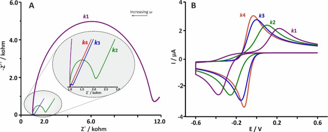
In real electrochemical systems, (Figure 14) the pattern of the Nyquist plot for a faradaic impedance spectrum over a wide range of frequencies usually involves both the semicircle (at this frequency region the electrochemical process is controlled by charge transfer phenomena) and the straight line (at this frequency region the electrochemical process is controlled by mass transfer phenomena) parts which can differ depending on the respective values of Cdl, Rct, and ZW. The effect of Rct, in relation to the heterogeneous transfer kinetics rate k0 (eq 57) of the redox species in the solution, as well as of Cdl are shown at the simulated Nyquist plots in Figures 15A and 16, respectively.
Figure 14.
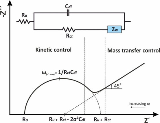
Randles equivalent electrical circuit over a wide frequency range.
Figure 15.
(A) Nyquist plots for an electrochemical process involving a redox reaction at different Rct corresponding to different heterogeneous transfer kinetics rates (k0) and (B) the respective cyclic voltammograms at the same k0 values. Ru = 1 kOhm, Cdl = 10–6 F, and Zw = 10–2 Ohm–1/2 s1/2.
Figure 16.
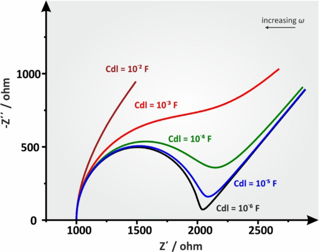
Simulated Nyquist plots of a Ru(Cdl[RctZw]) circuit at different Cdl values. Ru = 1 kOhm, Rct = 1 kOhm, and Zw = 10–2 Ohm–1/2 s1/2.
Most readers are presumably quite familiar with
cyclic voltammetry
measurements and thus the effect of Rct, as calculated by eq 57 for different k0 values, at the pattern
of a Nyquist plot for a specific electrochemical experiment, is presented
along with the simulated cyclic voltammograms of one electron (n = 1) redox reaction at the respective k0 values, provided by the Electrochemical Simulation Package
version 2.4 (developed by Prof. Carlo Nervi). Theoretically, a peak
potential separation value, ΔEp =
57/n, indicates a reversible redox reaction and increases
at semi reversible redox reactions at which k0 is lower (Figure 15B). In reversible electrochemical systems which typically
show fast kinetics, Rct becomes inconsequentially
small in comparison with the Ru and the Zw dominates over nearly the whole available
range of σ. When the system is so kinetically facile, the current
is limited by mass transfer phenomena, and the semicircular region
is not well-defined. The visibility of the kinetic region over the
mass transfer region (the clear distinction between the semicircle
and 45° straight line) is influenced by the relationship between
the Rct and RW. For the semicircle to be clearly seen the Rct ≥ RW = σ/√ω,
which leads to  , as usually happens for semireversible
electrochemical systems.4
Figure 16 shows the effect of the Cdl value on the pattern of a simulated Nyquist plot for the Randles circuit when all other parameters remain constant. It is obvious that distortion increases along with Cdl, eventually causing a complete disruption of the semicircle at extreme values (maroon line). In a real electrochemical system, the graphical approximation of the Rct value, for instance, would yield a systematic error in moderately increased Cdl values up to 10–4 F and would be unrealizable in even larger values. In such cases, the estimation of the Rct and σ values are possible only by using a proper fitting simulation software.
12. Constant Phase Element (CPE)
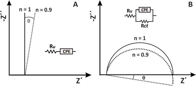
In the example illustrated in Figure 17A, the Nyquist plot for an ideally polarizable (blocking) electrode RuCdl shows a vertical line crossing the real impedance axis at Ru, while in Figure 17B, in the presence of a redox molecule, considering that the electrochemical reaction is not limited by mass transfer, the Nyquist plot shows a semicircle that can be modeled to an Ru(CdlRct) equivalent electrical circuit. Note that the semicircle is symmetric in the sense that the diameter (equals Rct) is two times the radial which corresponds to the maximum imaginary impedance of the system. In both cases, Cdl has been considered as an ideal capacitor the impedance of which is given as
| 69 |
This behavior can be experimentally obtained only in the case of perfectly flat electrodes, as for example the liquid Hg drop electrode. Working with common solid electrodes, such as macroscopically flat metal (monocrystalline or polycrystalline), or graphite electrodes, even more so with screen-printed or 3d-printed electrodes, the use of which in various (bio)sensing applications is continuously increasing,40,41 the impedimetric profile at the respective Nyquist plot will differ, indicating a deviation from the ideal case described above.
Figure 17.
Nyquist plots for CPE at (A) RuCdl and (B) Ru(CdlRct) circuits.
In the case of the blocking electrode, RuCdl, the impedimetric spectrum is tilted by an angle θ (Figure 17A), while in the case of a Ru(CdlRct) electrochemical cell the semicircle is depressed (Figure 17B). In these cases, the impedimetric data can be sufficiently modeled if instead of an ideal capacitor (Cdl), the so-called constant phase element (CPE) is used. The impedance of the CPE is sufficiently described by equation
| 70 |
where Yo in Ohm–1 sn or more correctly in F sn–1, is the parameter containing the capacitance information, and n is a constant ranging from 0 to 1. The exponent n defines the deviation from the ideal behavior and is related to the angle θ as
| 71 |
where θ is the phase deviation from
the ideal case (φ = 90°). As can be seen in Table 2, for n = 0.9,
θ = 9°, and φ is 81°, for n = 0.8, θ = 18°, and φ is 72°, etc. Moreover,
for n = 1, eq 70 equals eq 69 (Yo = Cdl). Yo has Farad units indicating that
CPE behaves as an ideal capacitor. On the other hand, for n = 0, eq 70 is written as ZCPE = Yo–1 (the
units of Yo are in Ohm) indicating that in this
case the CPE behaves as a resistor. Finally, for n = 0.5, eq 70 can be
written as  , that is, is equivalent to the Warburg
impedance (ZW).
Table 2. Behavior of CPE at Different n Values and the Corresponding Equations of Impedance.
| n | φ, degree | deviation (θ) from the ideal behavior, degree | impedance equation | |
|---|---|---|---|---|
| 1 | 90 | 0 | ||
| 0.9 | 81 | 9 | ||
| 0.8 | 72 | 18 | ||
| 0 | 0 | 90 | ||
| 0.5 | 45 | 45 |
Considering that the equation of the CPE (eq 70) does not directly provide capacitance values, an average double layer capacitance, C̅dl, (or effective capacitance) can be estimated depending on the equivalent circuit containing the CPE. For a blocking electrode (Ru – CPE in series) or when the electrochemical process involves a redox reaction under kinetic control, simulated by a circuit Ru(CdlRct) as in Figure 13F, Brag et al.42 proposed eqs 71 and 73, respectively, while for a film coated surface corresponds to a semicircle, (Rf – CPE connected in parallel), Hsu and Mansfeld43 proposed eq 74
| 72 |
| 73 |
| 74 |
The origin of CPE has been widely attributed to the surface roughness of solid electrodes, which in turn causes an uneven distribution of various properties, such as the solution resistances, interfacial capacitances, of current densities etc. across the electrode surface.44 However, related models have not been sufficiently supported by experimental data. Most of these models lead to a CPE behavior, however at a rather limited frequency range.45−48 Indeed, studies between electrodes with different roughness have shown that the increase of the electrode roughness leads to a CPE behavior closer to the ideal case.7 The behavior of CPE has also been attempted to be explained by fractal theory.49 Related models succeed to explain the behavior of CPE at blocking electrodes (models generate a linear spectrum tilted with respect to the imaginary impedance axis); however, in the presence of a redox probe, they predict asymmetric (skewed) semicircles instead of depressed semicircles obtained experimentally.50−52 Other theories, supported by experimental data, indicate that the origin of CPE is related to the mixed (fast) diffusion- (slow) kinetic-controlled adsorption of ions or other impurities of the electrolyte to the electrode surface.53−55 This explanation is also in line with experimental data showing that electrodes with increasing roughness exhibit lower deviation (the exponent n is closer to unit) in the sense that at a higher surface the coverage due to the adsorbed ions or impurities is smaller.56
13. Mass Transfer Impedance
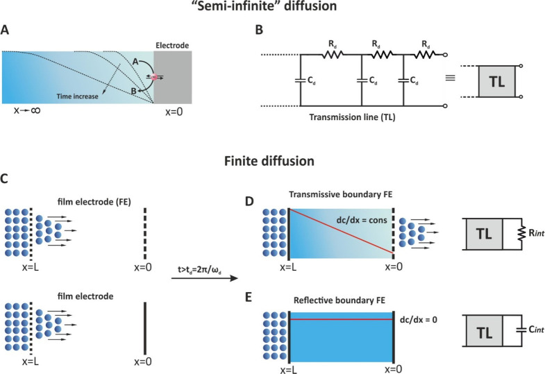
As stated before, Warburg impedance is a complex element which represents the mass transfer of redox species to the electrode surface and is depicted as a 45° line over the low frequency range of the Nyquist plot (Figure 14). This behavior refers to the time dependent (not-steady state) semi-infinite diffusion of the chemical species, in which, as shown in Figure 18A, there is a single boundary at the electrode/electrolyte interface, at a distance x = 0. Toward to the bulk solution, and under quiescent conditions, the diffusion layer is extended to infinite length (x → ∞) delimited by the dimensions of the electrochemical cell, while the concentration gradient is decreased with time.
Figure 18.
(A) The semi-infinite regime of an electrochemical cell, (B) the transmission line (TL) depiction of the semi-infinite regime, (C) finite boundary diffusion at t < td spans, (D) transmissive, and (E) reflective boundary at t > td.
The impedimetric response of Warburg impedance ZW in semi-infinite linear diffusion can be sufficiently modeled by a transmission line, of infinite length, which is represented by a network of resistors and capacitors that designates the diffusion resistance per unit length (Rd) and the chemical capacitance for diffusion per unit length (Cd), respectively (Figure 18B).57 This transmission line of infinite length models sufficiently Warburg impedance ZW as straight line of unity slope, as already discussed (section 11, Figure 13D).
For many electrochemical systems, however, the impedimetric response cannot be described by the Warburg impedance ZW of the semi-infinite linear diffusion model but by a two boundaries steady state diffusion region of finite length, x = L, where L is the length of the material in which the diffusional impedance is measured58 (Figure 18C). This material for example, can be a porous electrode of thickness L, which separate a solid electrolyte and a metal collector electrode in a fuel cell, a porous oxide film of thickness L between a metal base electrode and a lithium anion containing liquid electrolyte in a lithium anion battery, a redox polymer film of thickness L deposited on a metal electrode immersed in a liquid electrolyte, etc. As can be seen in Figure 18C, one of the sides of the material is permeable to the diffusing species (ions) involved in the electrochemical process, while the other side can be either permeable (Figure 18D) or impermeable (Figure 18E) to the diffusing species. Considering however the different geometries of the real electrochemical cell, it is more accurate to say that the finite-diffusion region (not side), after a time span
| 75 |
(D, is the diffusion coefficient of the species) is either permeable or impermeable to the diffusing ions. The time t refers to the time needed until the diffusing species reach the other side of the finite diffusion region. Until this time the concentration gradient is time dependent, and thus the system “behaves” like that the diffusion is semi-infinite. When the diffusing ions reach the other side of the diffusion region, the concentration gradient takes either a constant value different than zero or zero.
In this respect, the so-called finite diffusion can be distinguished into two cases:
-
(a)
When the finite-diffusion region is permeable to the diffusing species, a steady-state concentration gradient (dC/dx = constant) is established with the time and a current flows the electrochemical cell. This is the case of a transmissive or permeable boundary.
-
(b)
When after a time the finite-diffusion region is impermeable to the diffusing species, the charge transfer is not possible, and the concentration gradient of the diffusing species becomes zero (dC/dx = 0). This is the case of a reflective or impermeable boundary.
13.1. Transmissive Boundary
The finite diffusion with a transmissive (or permeable) boundary can be represented by a transmission line of finite length terminated with an interfacial resistance Rint (Figure 18D). The impedance of this shorted transmission line is referred to as ZO and can be modeled by the equation7,34
| 76 |
where Yo (Ohm–1 √s) is the diffusion related parameter and B is given as
| 77 |
where δ (cm) is the thickness of the diffusion layer and D (cm2 s–1) is the diffusion coefficient.
As can be seen in Figure 19, the impedance profile of Zo at low frequencies tends to that of ZW (until the entering species diffuse completely across the film) while at decreasing frequencies a semicircle is obtained indicating that the diffusing species has exited the finite length diffusing layer and a dc current flow within the film. It is noted that the thicker the film the lower the frequency at which the curvature of the impedance spectrum is observed.
Figure 19.
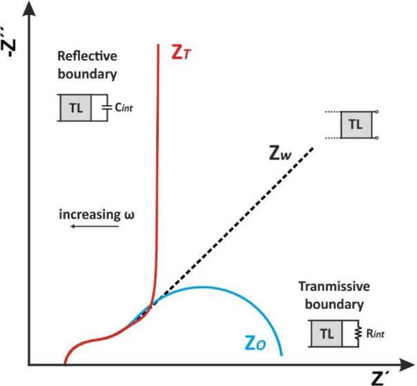
Stylized sketches of total impedance Nyquist plots at different mass transfer regimes.
Typical examples of finite length linear diffusion with a transmissive boundary include solid oxide59 or polymer membrane fuel cells,60 and the diffusing layer in a rotating disk electrode (RDE) experiment.7 At RDE voltammetry, we can easily achieve a finite length diffusion layer (mass transfer steady state), which is not changed with the time,61 in contrast with a stationary electrochemical system where the thickness of the diffusion layer is increasing with the time elapsed after a potential step [δ = (Dt)1/2]. In RDE voltammetry, the thickness of the diffusing layer is inversely proportional to the rotating speed as per equation
| 78 |
where ω is the angular rotation velocity of the electrode in rad s–1 and ν is the kinematic viscosity of the solution in m2 s–1. The effect of angular rotation velocity on the RDE’s impedance profile is shown at Figure 20. It can be observed that when the rotation speed of the RDE is very low (the diffusion layer is thick) the pattern of the impedimetric spectrum at low frequencies is approaching that of Warburg impedance ZW for semi-infinite linear diffusion.
Figure 20.
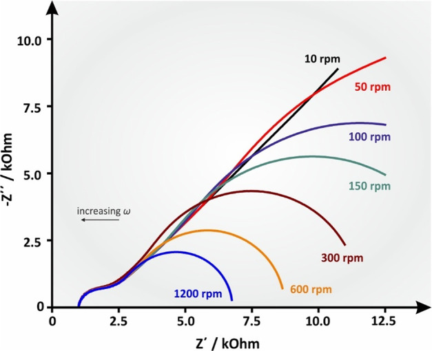
Simulated Nyquist plot of an RDE experiment with increasing angular velocity (ω) values, leading to increasing B values. Ru = 1000 Ohm, Cdl = 10–6 F, Rct = 1000 ohm, Y0 = 10–4 s1/2 ohm–1, B = 5.222 s–1 (ω = 10 rpm), B = 2.335 s–1 (ω = 50 rpm), B = 1.651 s–1 (ω = 100 rpm), B = 1.348 s–1 (ω = 150 rpm), B = 0.953 s–1 (ω = 300 rpm), B = 0.674 s–1 (ω = 600 rpm), and B = 0.477 s–1 (ω = 1200 rpm). D was deemed to be 7.6 × 10⁻⁶, as per the well-known redox couple ferro/ferricyanide, and ν was 0.01 cm2 s–1, which is the approximate value of water’s kinematic viscosity at 25 °C.
13.2. Reflective Boundary
As can be seen in Figure 18E, the concentration gradient of the redox species is zero and thus no charge transfer is possible. Typical examples of finite diffusion with reflective boundary include lithium diffusion in thin solid state oxide films,62,63 hydrogen diffusion into thin films of various hydrogen absorbing materials64 or mass transport of charge carriers at redox polymer film-coated electrodes65 etc. As can be seen in Figure 19, at low frequencies the diffusion of charges within the (polymer or oxide) films give rise to a Warburg impedance ZW with a unity slope while at decreasing frequencies the finite thickness of the film in combination with blocking properties of the impermeable interface, results in a (purely) capacitive behavior that shifts the phase angle from 45° to (almost) 90°. In this case, the diffusion impedance, referred to as ZT, is described by a transmission line of finite length terminated with an interfacial capacitor Cint and can be modeled by the equation7,34
| 79 |
where the symbols have the same meaning as indicated above in the case of the transmissive boundary. Figure 21 shows a simulated Nyquist plot of the total impedance consisting of a reflective boundary mass transfer impedance at increasing B values.
Figure 21.
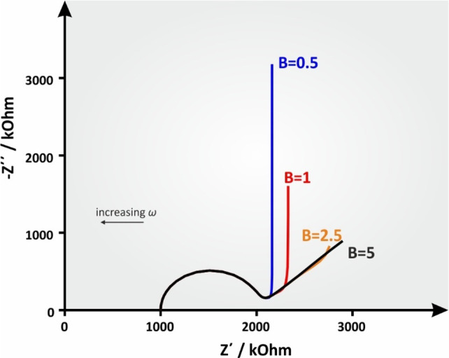
Simulated Nyquist plots of an ideal electrode surface with a reflective boundary at various (from 0.5 to 5 s–1) B values. Ru = 1000 ohm, Cdl = 10–6 F, Rct = 1000 ohm, Y0 = 10–3 s1/2 ohm–1.
Note: The only difference between eqs 76 and 79 relies
on that the eq 76 for
the transmissive boundary Zo(ω)
contains tanh, while the eq 79 for the reflective boundary ZT(ω) contains coth. Symbols Zo (from
coth) and ZT (from tanh) are originated
by the respective equations, written in admittance:  and
and  , respectively. Remember that coth(x) = 1/tanh(x). In some textbooks, Zo refers as finite length Warburg impedance ZFLW, while ZT refers
as finite space Warburg impedance ZFSW.
Finally, in electrochemical systems where the main heterogeneous electrochemical reaction is coupled with a preceding homogeneous first-order chemical reaction according to the following general scheme for a Chemical-Electrochemical (CE) reaction
the impedance response depends on the reaction rate of the chemical reaction (ka) in s–1, and under specific conditions can be modeled by equation:
| 80 |
This kind of mass transfer impedance was first reported by Gerischer66 and for this reason it is known as Gerischer impedance (ZG) for semi-infinite diffusion. Besides its original use for the interpretation of impedance measurements in CE reactions, it also has been used for fitting impedimetric data in polymer electrolyte membrane fuel cell,67 to interpret impedimetric data of the coupled bulk oxide ion diffusion and surface oxygen exchange reaction in solid oxide fuel cells,68 etc. More details on the use of ZG can be found in refs (7 and 69).
Figure 22 shows a simulated Nyquist plot of a redox electrochemical process coupled with a chemical reaction, with increasing ka values, to provide a concise view of the impact of the kinetics of the chemical reaction to the impedance spectrum.
Figure 22.
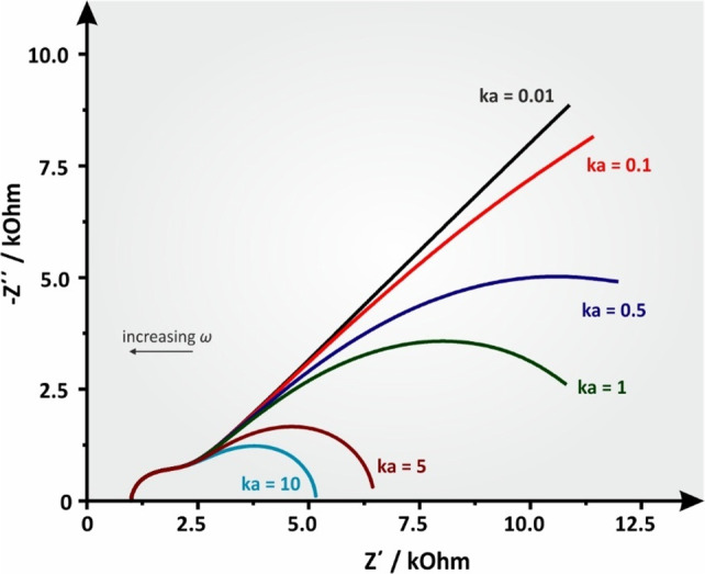
Simulated Nyquist plot of an ideal electrode surface at various (from 0.01 to 10 s–1) reaction rate values (ka). Ru = 1000 Ohm, Cdl = 10–6 F, Rct = 1000 Ohm, Y0 = 10–4 s1/2 ohm–1.
14. Porous Electrodes
Porous electrodes present an admittedly more complex pattern of impedance than common planar electrodes and should not be confused with rough electrodes having a random profile height. The size and the shape of pores govern the properties of a porous material. The first establishment of a complete impedimetric profile of a porous electrode was introduced in 1963 by De Levie.70 The term porous electrode refers to a porous conductive material (e.g., carbon black) or an electroactive film (e.g., a conductive polymer at its oxidized state) deposited on a base metal electrode. The impedance of a porous electrode can be represented by a uniform transmission line in a similar fashion to the mass transfer models described in Figure 18. In this model, pores are considered as circular cylinders of uniform diameter and of semi-infinite length while their external surface facing the solution is not taken into consideration. The pores are completely and homogeneously filled by the solution and since the resistance of the pore material is negligible, the only resistance present is the ohmic drop of the electrolyte. Thus, a uniform resistance (r1) and capacitance (C) per unit length is presented across the pore’s wall length. If we do consider that the electric properties of the solution/base electrode interface can be represented by a capacitor, then this simplified model (--RC-base electrode), depicted in (Figure 23A), approximates better a porous metal film or a conductive polymer, reaching the form of a reflective boundary (Figure 19). In this case, the impedance spectrum in the form of a Nyquist plot exhibits a straight line at 45° at high frequencies and a straight (perpendicular to y-axis) capacitance at low frequencies attributed to the charge saturation at the end of the pore which blocks any DC current from passing through the electrode substrate.
Figure 23.
Adapted illustration of De Levie’s model for a flooded porous electrode (A) in the absence and (B) in the presence of a redox molecule.
A modified transmission line can be used in the presence of a redox molecule, by adding a faradaic impedance element (ZF) in parallel to the capacitor, as depicted in Figure 23B. In fact, the De Levie model for the porous electrode in the absence of a redox molecule depicted in Figure 23A can be considered as a transmission line of a reflective boundary where the pore/base electrode interface is terminated by a capacitance much like the reflective boundary model explained for finite diffusion in section 13. Conversely, the De Levie model for the porous electrode in the presence of a redox molecule depicted in Figure 23B can be considered as a transmission line of a transmissive boundary terminated with a resistance like the transmissive boundary model explained in section 13. Since De Levie’s original model, various models have been introduced, e.g., by substituting C with a CPE or by considering different values of C (or CPE) along the pore length and the terminal C (or CPE) at the solution/base electrode interface. Examples of such complex porous models can be found in ref.71
15. Inductive Behavior
In section 6, we saw that when the circuit involves an inductor (a coiled wire) the latter gives rise an inductive reactance, XL = 2πfL, which is proportional to the frequency and inductance, while the current flow through the inductor lags the voltage by 90°. As a result, in the typical Nyquist plot −Z″ = f(Z′), we have considered so far in this tutorial, the inductive impedance appears below the x-axis (positive values) in the first quadrant (Z′ positive, −Z″negative). Depending on the origin of XL, actual inductance (ideally a straight line parallel to the positive part of the Z″ axis) or “inductive behavior” appears at the impedance spectrum at (very) high frequencies, while at (very) low frequencies the effect of inductance to the impedance spectrum appears as an “inductive loop”.
Inductive behavior at high frequencies is mainly associated with the length and the positioning of the cell cables, the contacts between the cables and the electrodes, the high impedance of the reference electrode, and instrumental artifacts. When ac current flows through a wire, a magnetic field surrounding the wire is generated and the change of rate of this magnetic field induces an electromotive force (emf) that opposing the cause producing the current. This property is termed self-inductance, is proportional to the length of the cables and appears at high frequencies (where XL is increasing and XC is low), while is more prominent at low impedance cells such as batteries and supercapacitors. The length of the cables also affects the stray capacitance between the WE–CE electrodes and the bandwidth of the potentiostat. As a result, at high frequencies, the use of extended cables might also cause a distortion (inductive behavior) of the measured impedance.37−39,72 A high impedance of the reference electrode, due to the design of the electrode or the fouling of the ceramic plug, slows down the voltage response of the electrode and impacts both the phase and the modulus of the measured impedance. The inductive behavior due to the reference electrode can be effectively compensated if the latter is connected in parallel with a 50 nF–1 μF capacitor and a Pt wire, as shown in Figure 24A.38,73
Figure 24.
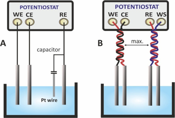
Suggested connections to alleviate inductive behavior due to (A) the high impedance of the reference electrode and (B) mutual inductance between WE-CE and RE-WS leads.
Besides self-inductance in the ac current-carrying leads (WE-CE), mutual inductance can also be generated in the voltage leads (RE-WS) when the magnetic field lines pass from, WE-CE to RE-WS wires. This will create an extra emf to RE-WS wires. As mutual inductance depends on the orientation of the wires with respect to each other and decreases as the distance between them increases, it is recommended, that each pair of cables is twisted with each other and placed to the maximum distance possible, as illustrated in Figure 24B.38 Note that this cable setup is effective only for low impedance systems.
On the other hand, the emergence of an inductive loop at the (very) low frequencies range is often subject to discussions or controversies, and thus, different models have been proposed to explain it depending on the type and operation of the examined electrochemical cell. The consensus view of most electrochemists is that inductive loops at low frequencies are observed when the electrochemical reactions are coupled by the formation of intermediate species absorbed on the electrode surface. A typical example is the dissolution of iron in acidic media (pH ≤ 5), which can be described by a reaction sequence involving up to three intermediate species,74,75 and the formation of soluble ferrous ion, Fe(II), that diffuses to the electrolyte.76,77
Depending on the experimental conditions (the pH of the electrolyte and the polarization–voltage), the impedance spectra exhibit different inductive behaviors. Impedance spectra for the dissolution of iron in 0.5 M H2SO4 at different corrosion potentials, are shown in Figure 25.77 Similar impedimetric profiles have been reported for magnesium corrosion in 0.5 M Na2SO4 where the inductive loop at low frequencies is attributed to absorbed intermediates (MgOHads).78
Figure 25.
Nyquist impedance spectra for the iron electrode in 0.5 M H2SO4 solution at various potentials. (a) Corrosion potential, −530 mV (vs SCE); (b) −450 mV; (c) −400 mV; (d) −350 mV. Reprinted with permission from ref (77). Copyright 2002 Elsevier.
The mechanism of the formation of such an inductive loop remains rather inconclusive since many different theories have been proposed to explain it. However, in general, considering a two-step electrode reaction with an adsorbed intermediate,
| 81 |
where A is the metal, A(I)ads is the adsorbed intermediate formed during the anodic dissolution of A, ka is the rate constant of the faradaic adsorption reaction, and kd is the rate constant of the faradaic desorption reaction, the formation of the inductive loop can be explained as follows:77 If ka ≫ kd or ka ≪ kd throughout the measurement, the inductive loop will not emerge. However, if the applied voltage influences the kinetics of the system dynamically by reversing the relationship of the rate constants during the measurement (for instance, if in the beginning of the measurement the rates’ relationship is ka ≫ kd and then becomes ka ≪ kd), an inductive loop will appear in the impedance spectrum. This can be said as a general rule, but in each system, a certain degree of deviation from that behavior may exist.
Other electrochemical systems exhibiting low frequency inductive loops include polymer electrolyte membrane (PEM) fuel cells and lithium-ion batteries. In PEM fuel cells, low frequency inductive loops have been attributed to side reactions and intermediates involved in the operation of the cells (for example, the formation of the electrochemically generated H2O2, during the oxygen reduction reaction, which imparts both the lifetime and the performance of the electrodes and the polymer electrolyte membrane), the formation of oxide layers onto the Pt catalyst and the subsequent dissolution of PtO as well as to the water transport through the membrane.79,80 In lithium-ion batteries, low frequency inductive loops have been explained by the formation of the so-called solid electrolyte interface81,82 while other studies attribute their origin in drift and corrosion phenomena.83
16. Practical Considerations
16.1. Frequency Range
The frequency range in an EIS experiment should be sufficiently wide to cover all the time constants of the processes (charging of the double layer, electron-transfer reactions, mass transfer phenomena) occurring in the electrochemical system under test. The highest frequency range is limited by the bandwidth of the potentiostat. Most analyzers offer a maximum frequency up to 1 MHz, which is sufficient to attain the high frequency limit of the impedance equal the uncompensated resistance of the electrolyte.84 In common electrochemical cells, the Ru can be measured at ca. 100 kHz, while in electrochemical systems involving solid electrolytes, the very fast time constant associated with the measurement of ionic conductivity within the bulk of the grains dictates measurements to be conducted at frequencies >5 MHz.85 Some vendors offer FRA analyzers enabling measurements up to 10 MHz along with cables suitable for measurements at high frequencies. Remember that at such high frequencies, especially at low impedance electrochemical systems, the inductance and the capacitance of the wires as well as the way they are connected with the cell (Figure 24B) will contribute to the overall impedance measured. The use of short wires suitable for such measurements is mandatory.
On the other hand, the lowest applied frequency is usually ranged from some mHz up to 0.1 Hz depending on the electrochemical system under test. Generally, measurements at low frequencies are time-consuming. For example, a measurement at 1 mHz takes (0.001 s–1 = 1000 s) ca. 17 min. Considering that in order to eliminate the noise of the signal is suggested that each spectrum to be taken more than one times (this option is provided by the acquisition software), measurements at these low frequencies are not practical. Moreover, at this time scale the condition of “stability” (see above) might be violated. Time consuming measurements at the mHz frequency range can be addressed by using the multisine option available in the acquisition software of the frequency response analyzers, which enables the simultaneous application of more than one excitation signals at different frequencies (for example, 5, 10 or even more) that are summed up to form a multisine excitation signal. The impedance response to this multisine excitation signal is recorded and deconvoluted by applying fast Fourier transforms to the impedance data for its discrete frequency. The use of multisine option is usually accompanied by a slightly disordered spectrum compared with that obtained by applying each frequency at a time; however, as stated above, it leads to faster acquisition of the spectrum.
16.2. Amplitude
The amplitude of the perturbating signal (voltage or current when the measurement is taken under potentiostatic or galvanostatic mode, respectively) should be high enough to induce a high signal-to-noise ratio response (a reliable, not noisy signal) and at the same time not so high in order to keep the system in a linear regime. The optimum amplitude of the excitation signal is different for high and low frequencies; however, for convenience, a single value is used for all the applied frequencies. Remember that an easy way to select the maximum permissible amplitude of the perturbation signal is to refer to the shape of the resulting Lissajous plots (Figure 6). A symmetric and stable ellipsis denotes that under the applied experimental conditions the system is both linear and stable, while a disordered ellipsis imposes the application of a lower amplitude signal.
Under potentiostatic modulation, a voltage amplitude of 5–10 mV is commonly used. When a value is adapted from the literature, the user should check if this value refers to the peak, peak-to-peak or the rms value (Figure 1). A Vp = 10 mV is translated into Vpp = 20 mV and Vrms = 7 mV. For measurements at fluids with high resistivity (nonaqueous electrolytes) the application of a considerably higher amplitude perturbating signal might be necessary. The ac excitation voltage amplitude is usually superimposed on a dc voltage. Depending on the application, the dc voltage usually refers to the OCP, or to the formal potential of the redox probe involved in the measuring solution, in the case of faradaic impedance measurements. For example, EIS measurements in an electrolyte containing the ferro/ferricyanide redox couple are commonly conducted at ca. 0.2 V.86
16.3. Connections
As mentioned above, EIS measurements can be conducted by using 2-, 3-, or 4-electrodes, while modern potentiostats feature four cables, two (WE, CE) for carrying the current and two (RE, WS) for measuring the voltage. Besides the length and the technical specifications of the wires, the influence of which on the impedance data is discussed above, the connection of these cables to the cell under study is also very important. A challenging case is that of a 2-electrode cell, such as a common battery.37,38,87,88 A 2-electrode battery can connect with the four cables of the potentiostat either in a two terminal (2T) or a four terminal (4T) configuration, as illustrated in Figure 26A.
Figure 26.
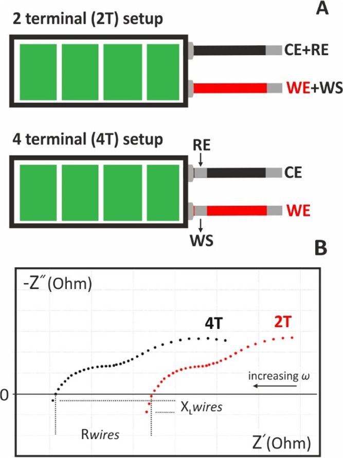
(A) 2-terminal and 4-terminal connections of a 2-electrode cell with the potentiostat and (B) the respective Nyquist plots adapted from ref.87 Courtesy of Metrohm Autolab B.V.
In both cases, the current IWE-CE that flows through the cell is the same, while the voltage in each case is given by the following equations
| 82 |
| 83 |
where ZBAT is the impedance of the battery and ZWIRE is the impedance of the wires. The impedance spectra obtained at each measuring configurations are illustrated in Figure 26B. The difference in the real impedance (at Z″ = 0) due to the resistance of the wires (R wires) and the difference of the imaginary impedance at the first quadrant due to the inductance of the wires (XL wires) are indicated.
16.4. Faraday Cage and Distortion of the Impedance Data by Other Equipment
The use of a Faraday cage, especially when measuring impedance at low-current electrochemical cells is highly recommended. In addition, the generation of time-varying magnetic fields by other equipment operating a short distance from the cell, such as the computer, stirrers etc. or even the power line, might induce mutual inductance thus impairing the impedance measurements. The influence is more severe when extended or unshielded cables are used. Where it is possible, other equipment should not be in operation during the impedance measurements.38,72
16.5. Data Validation and Simulation
Once a spectrum is obtained, the validity of the data should be checked by running the Kramers–Kronig test provided by the control software. By default, the number of RC circuits or RC serial arrangements is equal to the number of data points. If there is a chance that the measured signal is subject to noise, the number of circuits may be reduced to avoid both overfitting and the consequent incorporation of noise in the model. The “Tau-range factor” is a special parameter set to 1 by default. It is related to the distribution of RC-times in the circuits, which are kept fixed during the fit. In the Kramers–Kronig test, fit is only done on the R-value of each RC-circuit. The result of the test is the value of pseudo-χ2, the sum of squares of the relative residuals. In each case, the χ2 for the real and the imaginary part is reported (overall χ2 is a sum of real and imaginary χ2). Large χ2 value means bad fit, small value–good fit. In this case, the definition of “large” or “small” depends on the number and the value of data points. As a rule of thumb, values lower than 10–6 usually mean an excellent fit, reasonable between 10–5 and 10–6, marginal between 10–4 and 10–5 and bad for even higher values. Moreover, the residuals should be small and randomly distributed around zero. The test can be conducted on the real part, imaginary part or both parts of admittance/impedance (complex fit). When fitting is performed on a single part only, the second part of the measured data set is generated using Kramers–Kronig transformation (based on the assumption that the system obeys Kramers–Kronig criteria), and then, the χ2 for the second part is computed. Once the Kramers–Kronig test has been run successfully, data can be simulated to an equivalent electrical circuit in order to gain insight for the various electrochemical physical processes involved. Every set of data can be simulated to a complicated equivalent electrical circuit. It is important though for the circuit to be as simple as possible containing passive or distributed elements that can be correlated to electrochemical physical processes.
17. Utility of EIS in Energy Applications and Biosensing
17.1. Lithium-Ion Batteries
Since their commercialization in 1991, lithium-ion batteries have established themselves as the prime energy source in common everyday devices.89 As seen in Figure 27A a Li-ion battery presents a complex assembly starting with two current collectors on its sides (copper and aluminum foil, respectively), as well as the anode, which is commonly graphite or other porous carbon materials like carbon black, and the cathode which is commonly a lithium-intercalated metal oxide (LiMxOx where M can be Co, Ni, Mo, V etc.).90 Moreover, lithium salt-containing liquid electrolyte (e.g., LiPF6 in propylene carbonate) lies between the anode and the cathode to enable ion transfer between the electrodes. In real batteries, however, the anode and the cathode are in proximity, so a lithium-conducting separator electron-insulating membrane is also applied between them preventing electronic current from crossing each side to avoid short-circuits. To understand the impedimetric profile of a lithium-ion battery, we must consider how it works first. When a lithium-ion battery is charging, lithium ions are deintercalated from the lithium metal oxide of the cathode due to the loss of an electron by the positive bias of the charger. That electron flows through copper foil and through the charger creating a negative charge in the graphite in the anode. For this reason, the produced lithium ions are diffused through the separator and are consequently intercalated in the anode. Eventually, when charging is completed, the cathode will be completely deintercalated while the anode will be completely intercalated with lithium. Reversely, during a discharging process, lithium ions will be deintercalated from the now unstable anode producing one electron which flows through the battery connection until it reaches the cathode, which causes lithium ions to be diffused back to it, forming the stable LiMxOx. With that being said, it is evident that each part of a lithium-ion battery can be analyzed into different equivalent circuits as depicted in Figure 27A since it forms different interfaces with its adjacent elements.91,92 An actual impedimetric profile of a real battery is closer to that of Figure 27B, since the contribution of each distinctive element can be summed up to a more general equivalent circuit (for instance Rb stands for the bulk resistance of the half-cell, including the electrolyte, the electrode, and the separator).93 In the Nyquist plot presented here, a semicircle attributed to the interfacial characteristics and the charge transfer of the lithium ions is evident, coupled with the Warburg impedance attributed to the diffusion of the lithium ions from the electrolyte to the electrode or vice versa.
Figure 27.
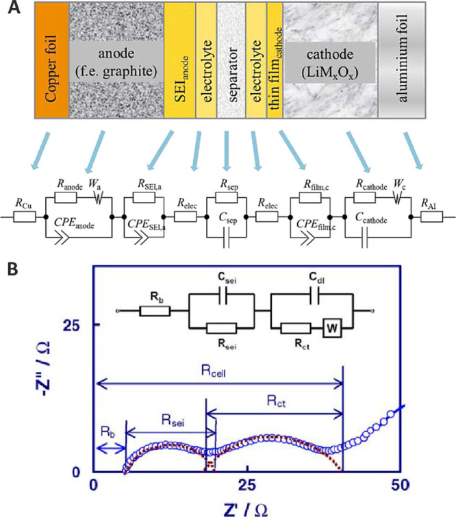
(A) Description of individual cell components with equivalent circuit elements. Reprinted with permission from ref (91). Copyright 2016 Wiley. (B) Equivalent circuit model of a lithium-ion half-cell system. Reprinted with permission from ref (93). Copyright 2004 Elsevier.
However, an additional semicircle is visible at the higher frequencies attributed to the interfacial characteristics of the solid electrolyte interface (SEI), that is, an organic layer created due to the decomposition of the liquid electrolyte near the anode surface, which mostly influences the electrochemical properties of the anode’s metal oxide.93−95 The existence of the SEI influences the inherent properties of the battery itself, such as its cycling stability. Additionally, there have been reported cases when an inductive loop also emerged in high frequencies due to the initial instability of the SEI while the eventual disappearance of the inductive loop can be used as a clue to the stabilization of the SEI layer.93
As explained above, standard lithium-ion batteries have been established using liquid electrolytes as charge carriers. However, contemporary literature has been occupied with the possibility of replacement of liquid electrolyte with solid electrolytes which exhibit faster ion conduction.96 When solid electrolytes are used, the impedimetric spectrum at the high frequencies region is expected to involve two different semicircles representing the difference in charge transfer within the bulk of the grains of the solid electrolyte (intragrain charge transfer) and the more conductive grain boundaries (intergrain charge transfer).97 Nevertheless, all-solid-state systems suffer from contact issues at “solid–solid” interfaces between the cathode and electrolyte composite.96 That is why hybrid solid/liquid electrolyte (SE/LE) systems have been proposed to improve cathode performance, which present a very interesting impedimetric system currently under investigation.
Fuchs et al.85 employed a mixed solid/ionic liquid electrolyte (SE/ILE) system between two symmetrical lithium metal electrodes (Li) and its impedimetric profile is shown in Figure 28A. The Nyquist plot of this setup exhibiting four semicircles, which have been divided to five different time constants [indicated as [RCPE](1), [RCPE](2), ... [RCPE](5)] using a proportional weighing method, is analyzed as follows: two in low frequencies for the transfer across the SE/ILE phase boundary, (RCPESLEI) and (RCPESEI), one related to the ion mobility between the grain boundaries (GB) of the solid electrolyte (RCPEGB) in intermediate frequencies, and one attributed to the ion mobility within the bulk grain (BG) of the solid electrolyte (RCPEBG) at higher frequencies. The uncompensated resistance of the liquid electrolyte is considered to be nil, since the electrolyte is present only as a very thin interlayer. Another semicircle is attributed to the electrochemical reaction (RCPEECR) in lithium metal anode. Note that complete identification of the (RCPEBG) related semicircle requires measurements at very fast excitation frequencies (typically over 5 MHz) for which high performance frequency response analyzers are required to produce safe results. A schematic of the whole cell separated by different interphases with the respective equivalent circuits is shown in Figure 28B.
Figure 28.
(A) Nyquist plot of Li|ILE|SE|Li (green line) cell with its respective fit and characteristic peak frequencies. (B) Schematic of the Li|ILE|SE|Li cell and the equivalent circuit used for fitting the impedance data. Li, Lithium electrode, SE, solid electrolyte, ILE, ionic liquid electrolyte, ECR, electrochemical reaction. Adapted with permission from ref (85). Copyright 2021 Wiley.
17.2. Solid Oxide Fuel Cells
Much like a battery, solid oxide fuel cells (SOFC) are also galvanic cells which operate in a similar fashion, using typically hydrogen as a fuel.98 These cells are composed of two thin, porous electrodes (deposited on metal collectors), which are separated by the solid electrolyte. Figure 29A shows a general schematic of a SOFC based on an oxygen ion conducting solid electrolyte. The most common solid electrolyte of this type is yttria-stabilized zirconia (YSZ),68,99 which at high temperatures (ca. >650 °C) exhibits a satisfactory conductivity. The procedure begins with molecular hydrogen flow toward the porous anode, at which two atoms of hydrogen are adsorbed and react with an oxygen ion initially provided by the electrolyte’s crystal lattice. This reaction produces water and releases 2 electrons, as per the half reaction:
| 84 |
Figure 29.
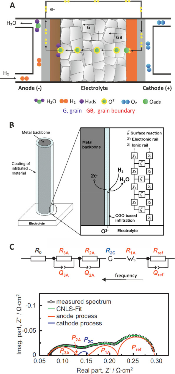
(A) Schematic of the working principle of a SOFC based on an oxygen ion conducting solid electrolyte. (B) Sketch of the situation where the anode microstructure is modeled as stainless-steel columns coated with a Ce0.8Gd0.2O1.9 (CGO) based infiltration and the electrochemical profile can be described by a transmission line. Reprinted with permission from ref (104). Copyright 2012 Elsevier. (C) CNLS-fit of impedance data to an equivalent electrical circuit that was developed by a preidentification of the impedance response by calculating and analyzing the corresponding distribution of relaxation times (DRT). Reprinted with permission from ref (103). Copyright 2013 Elsevier.
The produced water flows out of the system, while the released electrons travel through the anode’s current collector (depicted in gray) to the current collector/cathode/solid electrolyte three phase boundary. At this side, molecular oxygen of the gas inflow, is atomically adsorbed on the cathode and reacts with the electron pair, as per the half reaction:
| 85 |
producing oxygen ions which flow freely through the solid electrolyte until they reach the anode where this procedure repeats itself.
The operation of a SOFC, and consequently its impedimetric profile is highly dependent on the resistance of the solid electrolyte, that is, the ionic conduction within and between the grains as well as the electrochemical reactions at both the anode and cathode. Considering that the time constants for these processes are considerably different each other, over a wide frequency range from a few mHz to some MHz (see discussion in section 17.1), these processes can be ideally identified in an impedance spectrum, as three semicircles.
However, the impedimetric response due to the electrochemical processes at the anode and cathode are strongly dependent on the type of the electrodes, the type of the solid electrolyte, the type of the fuel, the water content, the working temperature, the gas supply etc. In this regard, even though a plethora of impedimetric studies on different SOFC have been reported, a consensus still does not exist regarding which processes are limiting the overall performance of a SOFC as well as on the discrimination of the respective impedance contribution to the whole spectrum. So far, impedimetric data have been analyzed and interpreted either with a porous transmission line modeling (Figure 29B),100 or with the distribution of relaxation times (DRT) method.101−103 This method enables the transformation of a Nyquist plot showing poorly separated semicircles to a DRT = f(frequency) plot showing well resolved peaks attributed to the different time constants involved in the spectrum, which then can be attributed to individual processes. An example of the DRT method for analyzing the impedimetric profile of a reformate fueled Ni/YSZ anode based SOFC103 is shown in Figure 29C.
The deconvolution of the impedimetric data to these five different semicircles (indicated in Figure 29C as processes (P); P3A, P2A, P2C, P1A, and Pref) can be conducted via a complex nonlinear least-squares (CNLS) method available in Zview software. The physical processes represented in this spectrum are as follows: Ro, overall ohmic losses; R3A/Q3A (Q stands for CPE) and R2A/Q2A, gas diffusion coupled with charge transfer reaction and ionic transport within the anode functional layer; R2C, a Gerischer element corresponding to the activation polarization of the cathode; R1A, a generalized finite length Warburg element representing the gas diffusion of H2/H2O within the anode substrate, and Rref/Qref representing the reformate operation of the fuel cell. Details are available in ref (103).
17.3. Dye Sensitized Solar Cells, IMVS, and IMPS Measurements
Dye-sensitized solar cells (DSSCs), developed by Michael Grätzel in 1991,105 are low-cost photovoltaic cells that convert light energy into electrical energy with an efficiency up to 14%. The construction of DSSCs is relatively simple. They are composed of two transparent conductive electrodes (ITO of FTO), separated by a liquid or gel electrolyte containing iodide/triiodide (I–/I3–) redox couple, which are pressed together to form a nonleaking cell. The anode is covered by a thin layer of a high surface area porous semiconductor (typically TiO2) impregnated with a dye, the sensitizer (typically the ruthenium complex-based dye N719). The principle of operation of a DSSC is depicted in Figure 30A. The basic characterization of a DSSC involves the construction of a dc current–voltage (I/V) curve under, different, constant light intensities. Under potentiostatic control the voltage is scanned from V = 0 (short-circuit potential where the Isc = max) until reaching the OCP where I = 0. The product of each I/V pair values gives the power (P = VI), as illustrated in the stylized sketch in Figure 30B.
Figure 30.
(A) Schematic representation of a DSSC and (B) current–voltage plot of a DSSC. The gray area denotes the voltage perturbation around OCP and the current perturbation around Isc defining the examined IMVS and IMPS areas under modulated light intensity (C) A simplified experimental setup for the generation of modulated light intensities and cables connection at IMPS and IMVS measurements (D) Imaginary component −Z″(IMVS) of the IMVS transfer function versus the frequency range from 10 kHz to 100 mHz at three light intensities 5 (blue dots), 10 (red dots), and 50 mW/cm2 (green dots) with a DSSC, using the N719 dye. Courtesy of Metrohm Autolab B.V.109
Besides dc measurements, EIS measurements at different, constant light intensities can also provide mechanistic data for the DSSC. Details on the EIS analysis of the DSSCs, available in refs (106−108), will be skipped and our attention will be focused to two other measurements in which the DSSC is illuminated, not by a constant light intensity, but by a frequency-depended light intensity Φ(ω) (mW cm–2).109,110 That is, at high frequencies the light blinks fast, at lower frequencies blinks slower while at very low frequencies (f → 0) the light tends to be constant. A simplified experimental setup for the generation of modulated light intensity (the input signal) is shown in Figure 30C. Depending on the cabling, two different sinusoidal output signals which have the same frequency with the input signal, but differ in magnitude and phase, can be measured: The current (when the electrodes of the DSSC are connected with the WE-CE leads) or the voltage (when the electrodes of the DSSC are connected with the RE-S leads). Therefore, two new transfer functions enabling the description of the input/output relation in each case occur:
-
(a)The Intensity Modulated Photocurrent Spectroscopy (IMPS) transfer function
that can be calculated by measuring the ac current generated at the DSSC
86
when it is illuminated by modulated light intensity
87
under potentiostatic control at V = 0 (short-circuit conditions) and subsequent analysis of the signals. From the peak frequencies, fp(IMPS), of the resulting plots of the imaginary component −Z″(IMPS) versus the frequency, at the different light intensities, the electron transport time constants, τtr = 1/2πfp(IMPS), can be evaluated. Data show that the electron transport is faster when the light intensity increases.
88 - (b)
From the peak frequencies, fp(IMVS), of the resulting plots of the imaginary component −Z″(IMVS) versus the frequency, at the different light intensities (indicated with arrows in Figure 30D), the electron recombination time constants, τrec = 1/2πfp(IMVS), can be evaluated. Data show that upon the increase of the light intensity the recombination rate increases or otherwise, the electron lifetime decreases. The above time constants are also very useful to evaluate the efficiency of a DSSC by calculating the charge-collection efficiency, as per equation, ηcc = 1–(τtr/τrec). It stands to reason that high efficiencies can be achieved by increasing the time for electron recombination or decreasing the electron transport time through the pores of the anode.
17.4. Capacitive and Impedimetric Biosensors
Biosensors are analytical devices integrating a physical transducer (for example, an electrode) and a biochemical transducer (for example, an enzyme, an antibody, a single-stranded DNA, an aptamer etc.) that are in ultimate contact, and translate the concentration of the target analyte(s) into an electrical signal.111 The operation of capacitive biosensors is based on the alteration of the dielectric properties and/or the expansion of the dielectric layer at the electrode/electrolyte interface due to the specific interaction between a surface confined receptor (for example, an antibody, Ab) with an analyte specific to the receptor (for example, an antigen, Ag). According to equation,
| 91 |
where ε, is the dielectric constant of the medium at the electrode/electrolyte interface, εo, is the permittivity of free space, A, is the surface area of the electrode, and, d, is the thickness of the attached layers onto the electrode surface, the capacitance of the resulting biosensor (electrode/Ab) is decreasing due to the specific interaction between the immobilized receptor and the soluble target and the formation of the Ab-Ag immunocomplex on the electrode surface (electrode/Ab-Ag) (Figure 31). Obviously, the response of a capacitive biosensor is dependent on the size and the concentration of the target analyte and thus this biosensor type is mostly indicated for the sensing of bulky targets, such as proteins or even better, cells.112−117 As regards, the formation of the Ab-Ag immunocomplex results in alteration of the dielectric properties of the medium as water molecules (ε = 80) are replaced by compounds with lower dielectric constants (for example, the dielectric constant of a protein is ca. ε = 20.118 Capacitance changes due to Ab-Ag interactions are measured at low excitation frequencies, typically up to a few kHz. The performance of capacitive immunosensors is greatly affected by the nonideal capacitive behavior of the various layers that build the biosensor. Commonly, the immobilization of Abs onto the electrode surface is implemented through an insulating layer deposited or developed on the electrode surface (self-assembled monolayers of thiols, anodic oxide layers, electropolymerized nonconductive films etc.) that bears proper functional groups aiming (i) the effective immobilization of the recognition molecules (Abs) and (ii) the electrode assembly to behave as an ideal capacitor. However, the inherent nonideal dielectric character of biomolecules as well as surface defects at the insulating layer cause the whole assembly to deviate from the ideal capacitive behavior thus impairing the detection capabilities of the biosensor.
Figure 31.
Schematic representation of a capacitive biosensor showing the buildup of the biosensor and the biorecognition event where the total capacitance is described by various capacitors in series. Cdl, capacitance of the electric double layer; IL, insulating layer; Ab, antibody; Ag, antigen (the target analyte).
As a result, faradaic impedance measurements, in the presence of a redox couple in the measuring solution, have been considered as an alternative property for probing biomolecules interactions.112−115,119,120 In this case, the impedance spectra can be modeled by a Randles circuit in which the charge-transfer resistance (Rct) varies in a concentration dependent fashion, depending on the flux rate of the redox molecules to the electrode surface that is being polarized to the formal potential of the redox couple (an equimolar mixture of [Fe(CN)6]3–/4– is often used for this purpose). The flux rate of the redox probe is controlled by the extent of the formation of the Ab–Ag immunocomplex. The latter acts as a physical barrier which causes a concentration dependent lowering of the flux that is manifested by the respective increase of the charge-transfer resistance. Depending on the measuring pH and the isoelectric point (pI) of the biomolecules, the flux rate is also affected by attractive or repulsing forces of columbic nature between the biosensor’s surface and the molecules of the redox probe. The pI of a biomolecule refers to the pH at which the net charge of the biomolecule is zero. Thus, when pH > pI the biomolecule is negatively charged and when pH < pI the biomolecule is positively charged. Figure 32A shows a faradaic impedimetric immunosensor for the detection of Salmonella typhimurium in milk samples, which is based on gold electrodes (AuE) modified with a mixture of thiol-based SAMs which was used as an anchoring layer for the immobilization of Abs specific to the target bacteria though a bifunctional linker (glutaraldehyde). Non-specific binding sites on the electrode surface were blocked by depositing an inert protein (BSA). Impedance spectra were obtained in phosphate buffered saline, pH 7 containing [Fe (CN)6]3–/4– at 0.2 V vs Ag/AgCl 3 M KCl. As shown in Figure 32B, in the presence of the target bacteria (Salmonella typhimurium) in the culture sample, the Rct increases as the electron-transfer reaction is hindered by both the formation of the Ab-Ag immunocomplex and the repulsive forces between the negatively charged cells (more precisely, cell confined proteins) and the negatively charged [Fe (CN)6]3–/4– molecules. Crucially, the response of the biosensor to another bacteria (Escherichia coli) is nil, demonstrating a high selectivity attributed to the immobilized antibodies.
Figure 32.
(A) Tentative view of the different modification and recognition steps of the BSA-blocked Au/MUAM-MH/GA/Anti-SA immunosensors and (B) Nyquist plots showing the impedimetric response of the immunosensor (a) before and after its incubation with (b) E. coli and (c) S. typhimurium culture samples for 1 h. Initial concentration of bacteria, 106 cfu mL–1. Measuring conditions, 0.1–105 Hz at +0.200 V bias (10 mV rms). Electrolyte, 5 mM hexacyanoferrate(II)/(III) (1 + 1 mixture) in PBS solution, pH 7. MUAM, 11-Amino-1-undecanethiol hydrochloride; MH, 6-Mercapto-1-hexanol; GA, glutaraldehyde. Reprinted with permission from ref (86). Copyright 2008 ACS Publications.
Compared with capacitive biosensors, faradaic impedimetric biosensors are usually considered to be more sensitive. However, the ability of the former to operate at a reagentless mode is an attractive feature for point-of-care applications. The analytical features of faradaic impedimetric biosensors also depend on the thickness of the sensing layer, the electrocatalytic properties of the base electrode (or the modified electrode surface) toward the redox probe molecules, the size of the redox probe molecules, the density of the biorecognition layer, the blocking of the nonspecific binding sites as well as the accessibility of the target analytes to the surface of the biosensor. A high signal-to-noise ratio that would ensure a low detection limit and high sensitivity requires that the electron-transfer process, in the absence of the target, is quite facile and thereby offering a very low background signal (that is, a narrow semicircle with a very low Rct) over which small signals changes (corresponding to low concentrations of the target) can be reliably measured. The sensitivity of the measurements can also be improved when bulky redox molecules are used instead of small redox molecules that can freely penetrate through the Ab-Ag immunocomplex. Even though the [Fe (CN)6]3–/4– redox couple, due to its low cost, highly solubility and its low formal potential is widely used in such applications, the use of bulky redox species, such as the silicotungstic acid hydrate (H4SiO4·12WO3·xH2O) heteropolyacid can be evaluated for the enhancement of the sensitivity.121 Note though that in this case, the detection range is expected to be narrower since the penetration (diffusion) rate of the (bulky) redox molecules through the immunocomplex will reach a plateau even at lower concentration of the target.
Another major challenge is that EIS biosensors can also be associated with nonspecific signal changes that could be easily mistaken for specific interactions. Selectivity is particularly important in real samples where the analyte concentration can be much smaller than the concentration of nontarget molecules. Commonly, the blocking of the nonspecific binding sites is attainable by covering the Ab-modified electrode surface with a protein, such as BSA. However, this step should be carefully optimized as extended BSA coverage will also block the specific binding sites, thereby resulting in poor response. Finally, the detection capabilities of EIS biosensors are greatly affected by the bioactivity of the immobilized recognition biomolecules. In this perspective, the surface concentration of the functional groups which are used for the immobilization of the recognition biomolecules should be carefully selected. In the example illustrated in Figure 32, MH serves as a “dilutor” of MUAM that brings the functional amino headgroups for the immobilization of Abs, thus minimizing steric hindrances. High loadings of MUAM might also result in the immobilization of antibodies through multiple binding sites that in turn, can lead to reduced flexibility (rigidity of binding) and binding capacity of Abs to the target molecules.
Acknowledgments
The tutorial material included in the Supporting Information was developed based on the previous work done by Prof. Constantinos Efstathiou, with his permission.
Glossary
Vocabulary
- transfer function
the relationship between the output signal of a linear time-invariant system to the input signal
- EIS
based on the perturbation of an electrochemical system, via the application of a small amplitude sinusoidal signal (ac voltage or ac current) over a wide range of frequencies and the monitoring of the sinusoidal response (current or voltage, respectively) of the system toward the applied perturbation
- time constant (τ)
a measure of the time behavior of a process and corresponds to the time that a system needs to reach the ca. 63% of its maximum response or to decay to the ca. 37% of its original value
- Kramers–Kronig test
a test is used to check the validity of the impedance data. The Kramers–Kronig relations enable the calculation of the real part of the impedance from the imaginary part and vice versa. In a causal system, these parts are related.
- Randles equivalent electrical circuit
the uncompensated resistance of the electrolyte Ru, connected in series with a parallel combination of the capacitance of the electric double layer (C or CPE) with the charge-transfer resistance (Rct) due to a faradaic reaction and the Warburg impedance, ZW
- constant phase element (CPE)
used to model an imperfect capacitor
- Warburg impedance, ZW
expresses the difficulty of mass transport of the redox species to the electrode surface considering a semi-infinite linear diffusion. It is modeled by a straight line with slope 1
Supporting Information Available
The Supporting Information is available free of charge at https://pubs.acs.org/doi/10.1021/acsmeasuresciau.2c00070.
A user interactive excel file containing eight different model circuits (ZIP)
The authors declare no competing financial interest.
Supplementary Material
References
- Barsoukov E.; MacDonald J. R.. Impedance Spectroscopy: Theory, Experiment, and Applications, 2nd ed.; Wiley-VCH, 2018. [Google Scholar]
- Orazem M. E.; Tribollet B. A Tutorial on Electrochemical Impedance Spectroscopy. ChemTexts 2020, 6 (2), 12. 10.1007/s40828-020-0110-7. [DOI] [Google Scholar]
- Orazem M.; Tribollet B.. Electrochemical Impedance Spectroscopy, 2nd ed.; Wiley-VCH, 2008. [Google Scholar]
- Bard A. J.; Faulkner L. R.; White H. S.. Electrochemical Methods: Fundamentals and Applications; Wiley-VCH, 2022. [Google Scholar]
- Brett C. M. A.; Brett A. M. O.. Electrochemistry Principles, Methods and Applications; Oxford University Press, 1994. 10.1515/bmte.1999.44.s2.11. [DOI] [Google Scholar]
- Scholtz F.Electroanalytical Methods, Guide to Experiments and Applications, 2nd revised and extended ed.; Springer Verlag: Berlin, 2010. [Google Scholar]
- Lasia A.Electrochemical Impedance Spectroscopy and Its Applications; Springer: New York, 2014. 10.1007/978-1-4614-8933-7. [DOI] [Google Scholar]
- Lvovich V. F.Impedance Spectroscopy: Applications to Electrochemical and Dielectric Phenomena; Wiley-VCH, 2015. 10.1002/9781118164075. [DOI] [Google Scholar]
- Wang S.; Zhang J.; Gharbi O.; Vivier V.; Gao M.; Orazem M. E. Electrochemical Impedance Spectroscopy. Nat. Rev. Methods Prim. 2021, 1 (1), 41. 10.1038/s43586-021-00039-w. [DOI] [Google Scholar]
- Magar H. S.; Hassan R. Y. A.; Mulchandani A. Electrochemical Impedance Spectroscopy (EIS): Principles, Construction, and Biosensing Applications. Sensors 2021, 21, 6578. 10.3390/s21196578. [DOI] [PMC free article] [PubMed] [Google Scholar]
- Park S.-M.; Yoo J.-S. Electrochemical Impedance Spectroscopy for Better Electrochemical Measurements. Anal. Chem. 2003, 75 (21), 455A–461A. 10.1021/ac0313973. [DOI] [PubMed] [Google Scholar]
- Sluyters-Rehbach M. Impedances of Electrochemical Systems: Terminology, Nomenclature and Representation - Part I: Cells with Metal Electrodes and Liquid Solutions (IUPAC Recommendations 1994). Pure Appl. Chem. 1994, 66 (9), 1831–1891. 10.1351/pac199466091831. [DOI] [Google Scholar]
- Randles J. E. B. Kinetics of Rapid Electrode Reactions. Discuss. Faraday Soc. 1947, 1, 11–19. 10.1039/df9470100011. [DOI] [Google Scholar]
- Sluyters J. H. On the Impedance of Galvanic Cells: I. Theory. Recl. des Trav. Chim. des Pays-Bas 1960, 79 (10), 1092–1100. 10.1002/recl.19600791013. [DOI] [Google Scholar]
- Smith D. E. Theory of the Faradaic Impedance. Relationship between Faradaic Impedances for Various Small Amplitude Alternating Current Techniques. Anal. Chem. 1964, 36 (6), 962–970. 10.1021/ac60212a007. [DOI] [Google Scholar]
- Warburg E. Ueber Das Verhalten Sogenannter Unpolarisirbarer Elektroden Gegen Wechselstrom. Ann. Phys. 1899, 303 (3), 493–499. 10.1002/andp.18993030302. [DOI] [Google Scholar]
- Timmer B.; Sluyters-Rehbach M.; Sluyters J. H. On the Impedance of Galvanic Cells: XIX. The Potential Dependence of the Faradaic Impedance in the Case of an Irreversible Electrode Reaction; Experimental Verification for the Redox Couple Eu3+/Eu2+ In 1 M NaClO4 and The Mechanism of the Zn2+/Zn(Hg) Reac. J. Electroanal. Chem. Interfacial Electrochem. 1967, 14 (2), 181–191. 10.1016/0022-0728(67)80068-8. [DOI] [Google Scholar]
- https://www.metrohm.com (accessed on 10 February 2023).
- https://www.ameteksi.com (accessed on 10 February 2023).
- https://www.biologic.net (accessed on 10 February 2023).
- https://www.gamry.com (accessed on 10 February 2023).
- https://www.zahner.de (accessed on 10 February 2023).
- https://www.ivium.com (accessed on 10 February 2023).
- Peter L. M.; Li J.; Peat R.; Lewerenz H. J.; Stumper J. Frequency Response Analysis of Intensity Modulated Photocurrents at Semiconductor Electrodes. Electrochim. Acta 1990, 35 (10), 1657–1664. 10.1016/0013-4686(90)80022-G. [DOI] [Google Scholar]
- Deslouis C.; Gabrielli C.; Fanchine P. S.; Tribollet B. Electrohydrodynamical Impedance on a Rotating Disk Electrode: I. Redox System. J. Electrochem. Soc. 1982, 129 (1), 107. 10.1149/1.2123728. [DOI] [Google Scholar]
- Citti I.; Aaboubi O.; Chopart J. P.; Gabrielli C.; Olivier A.; Tribollet B. Impedance of Laminar Free Convection and Thermal Convection at a Vertical Electrode. J. Electrochem. Soc. 1997, 144 (7), 2263. 10.1149/1.1837801. [DOI] [Google Scholar]
- Rotenberg Z. A. Thermoelectrochemical Impedance. Electrochim. Acta 1997, 42 (5), 793–799. 10.1016/S0013-4686(96)00337-4. [DOI] [Google Scholar]
- Millet P. Pneumatochemical Impedance Spectroscopy. 1. Principles. J. Phys. Chem. B 2005, 109 (50), 24016–24024. 10.1021/jp053350m. [DOI] [PubMed] [Google Scholar]
- Efstathiou C.Chemical Intrumentation-Microcomputers (in Greek); Self-published, Athens, 2002. [Google Scholar]
- https://www.metrohm.com/en/applications/application-notes/autolab-applikationen-anautolab/an-eis-006.html (accessed on 10 February 2023).
- Szekeres K. J.; Vesztergom S.; Ujvári M.; Láng G. G. Methods for the Determination of Valid Impedance Spectra in Non-Stationary Electrochemical Systems: Concepts and Techniques of Practical Importance. ChemElectroChem. 2021, 8 (7), 1233–1250. 10.1002/celc.202100093. [DOI] [Google Scholar]
- Boukamp B. A.; Ross Macdonald J. Alternatives to Kronig-Kramers Transformation and Testing, and Estimation of Distributions. Solid State Ionics 1994, 74 (1), 85–101. 10.1016/0167-2738(94)90440-5. [DOI] [Google Scholar]
- Boukamp B. A. A Linear Kronig-Kramers Transform Test for Immittance Data Validation. J. Electrochem. Soc. 1995, 142 (6), 1885. 10.1149/1.2044210. [DOI] [Google Scholar]
- Boukamp B. A. A Nonlinear Least Squares Fit Procedure for Analysis of Immittance Data of Electrochemical Systems. Solid State Ionics 1986, 20 (1), 31–44. 10.1016/0167-2738(86)90031-7. [DOI] [Google Scholar]
- https://www.ameteksi.com/-/media/ameteksi/download_links/documentations/library/princetonappliedresearch/app_note_ac-1.pdf?revision=8886108d-2d8f-4320-96eb-a4c724c37658 (accessed on 10 February 2023).
- https://www.gamry.com/application-notes/EIS/eis-of-organic-coatings-and-paints/ (accessed on 10 February 2023).
- https://www.biologic.net/documents/impedance-from-the-experimental-side-impedance/ (accessed on 10 February 2023).
- https://www.gamry.com/assets/uploads/resources/EIS-Difficult-Samples.pdf (accessed on 10 February 2023).
- Erinmwingbovo C.; La Mantia F. Estimation and Correction of Instrument Artefacts in Dynamic Impedance Spectra. Sci. Rep. 2021, 11 (1), 1362. 10.1038/s41598-020-80468-x. [DOI] [PMC free article] [PubMed] [Google Scholar]
- Randviir E. P.; Banks C. E. Electrochemical Impedance Spectroscopy: An Overview of Bioanalytical Applications. Anal. Methods 2013, 5 (5), 1098–1115. 10.1039/c3ay26476a. [DOI] [PubMed] [Google Scholar]
- Taleat Z.; Khoshroo A.; Mazloum-Ardakani M. Screen-Printed Electrodes for Biosensing: A Review (2008–2013). Microchim. Acta 2014, 181 (9), 865–891. 10.1007/s00604-014-1181-1. [DOI] [Google Scholar]
- Brug G. J.; van den Eeden A. L. G.; Sluyters-Rehbach M.; Sluyters J. H. The Analysis of Electrode Impedances Complicated by the Presence of a Constant Phase Element. J. Electroanal. Chem. Interfacial Electrochem. 1984, 176 (1), 275–295. 10.1016/S0022-0728(84)80324-1. [DOI] [Google Scholar]
- Hsu C. H.; Mansfeld F. Concernng the Conversion of the Constant Phase Element Parameter Y0 into a Capacitance. Corrosion 2001, 57 (9), 747–748. 10.5006/1.3280607. [DOI] [Google Scholar]
- Lasia A. The Origin of the Constant Phase Element. J. Phys. Chem. Lett. 2022, 13 (2), 580–589. 10.1021/acs.jpclett.1c03782. [DOI] [PubMed] [Google Scholar]
- Kerner Z.; Pajkossy T. On the Origin of Capacitance Dispersion of Rough Electrodes. Electrochim. Acta 2000, 46 (2), 207–211. 10.1016/S0013-4686(00)00574-0. [DOI] [Google Scholar]
- Pajkossy T.; Jurczakowski R. Electrochemical Impedance Spectroscopy in Interfacial Studies. Curr. Opin. Electrochem. 2017, 1 (1), 53–58. 10.1016/j.coelec.2017.01.006. [DOI] [Google Scholar]
- Huang V. M.-W.; Vivier V.; Orazem M. E.; Pébère N.; Tribollet B. The Apparent Constant-Phase-Element Behavior of an Ideally Polarized Blocking Electrode: A Global and Local Impedance Analysis. J. Electrochem. Soc. 2007, 154 (2), C81. 10.1149/1.2398882. [DOI] [Google Scholar]
- Emmanuel B. Computation of Ac Responses of Arbitrary Electrode Geometries from the Corresponding Secondary Current Distributions: A Method Based on Analytic Continuation. J. Electroanal. Chem. 2007, 605 (2), 89–97. 10.1016/j.jelechem.2007.03.015. [DOI] [Google Scholar]
- de Levie R. Fractals and Rough Electrodes. J. Electroanal. Chem. Interfacial Electrochem. 1990, 281 (1), 1–21. 10.1016/0022-0728(90)87025-F. [DOI] [Google Scholar]
- Pajkossy T.; Nyikos L. Impedance of Planar Electrodes with Scale-Invariant Capacitance Distribution. J. Electroanal. Chem. 1992, 332 (1), 55–61. 10.1016/0022-0728(92)80340-A. [DOI] [Google Scholar]
- Pajkossy T. Impedance of Rough Capacitive Electrodes. J. Electroanal. Chem. 1994, 364 (1), 111–125. 10.1016/0022-0728(93)02949-I. [DOI] [Google Scholar]
- de Levie R. On the Impedance of Electrodes with Rough Interfaces. J. Electroanal. Chem. Interfacial Electrochem. 1989, 261 (1), 1–9. 10.1016/0022-0728(89)87121-9. [DOI] [Google Scholar]
- Pajkossy T.; Wandlowski T.; Kolb D. M. Impedance Aspects of Anion Adsorption on Gold Single Crystal Electrodes. J. Electroanal. Chem. 1996, 414 (2), 209–220. 10.1016/0022-0728(96)04700-6. [DOI] [Google Scholar]
- Pajkossy T. Capacitance Dispersion on Solid Electrodes: Anion Adsorption Studies on Gold Single Crystal Electrodes. Solid State Ionics 1997, 94 (1), 123–129. 10.1016/S0167-2738(96)00507-3. [DOI] [Google Scholar]
- Kerner Z.; Pajkossy T. Measurement of Adsorption Rates of Anions on Au(111) Electrodes by Impedance Spectroscopy. Electrochim. Acta 2002, 47 (13), 2055–2063. 10.1016/S0013-4686(02)00073-7. [DOI] [Google Scholar]
- Martin M. H.; Lasia A. Influence of Experimental Factors on the Constant Phase Element Behavior of Pt Electrodes. Electrochim. Acta 2011, 56 (23), 8058–8068. 10.1016/j.electacta.2011.02.068. [DOI] [Google Scholar]
- Kim J.-S.; Pyun S.-I. Comparison of Transmissive Permeable and Reflective Impermeable Interfaces between Electrode and Electrolyte. J. Solid State Electrochem. 2011, 15 (11), 2447–2452. 10.1007/s10008-011-1393-9. [DOI] [Google Scholar]
- Yu H.-C.; Adler S. B.; Barnett S. A.; Thornton K. Simulation of the Diffusional Impedance and Application to the Characterization of Electrodes with Complex Microstructures. Electrochim. Acta 2020, 354, 136534. 10.1016/j.electacta.2020.136534. [DOI] [Google Scholar]
- Kim J.-S.; Pyun S.-I. Kinetics of Oxygen Reduction at Composite Electrodes with Controlled Three-Phase Boundaries by Patterning YSZ Column. Electrochim. Acta 2009, 54 (3), 952–960. 10.1016/j.electacta.2008.08.037. [DOI] [Google Scholar]
- Lee S.-J.; Pyun S.-I. Effect of Annealing Temperature on Mixed Proton Transport and Charge Transfer-Controlled Oxygen Reduction in Gas Diffusion Electrode. Electrochim. Acta 2007, 52 (23), 6525–6533. 10.1016/j.electacta.2007.04.081. [DOI] [Google Scholar]
- https://www.metrohm.com/en/applications/application-notes/autolab-applikationen-anautolab/an-ec-001.html (accessed on 10 February 2023).
- Ho C.; Raistrick I. D.; Huggins R. A. Application of A-C Techniques to the Study of Lithium Diffusion in Tungsten Trioxide Thin Films. J. Electrochem. Soc. 1980, 127 (2), 343. 10.1149/1.2129668. [DOI] [Google Scholar]
- Pyun S.-I.; Bae J.-S. The Ac Impedance Study of Electrochemical Lithium Intercalation into Porous Vanadium Oxide Electrode. Electrochim. Acta 1996, 41 (6), 919–925. 10.1016/0013-4686(95)00386-X. [DOI] [Google Scholar]
- Lim C.; Pyun S.-I. Theoretical Approach to Faradaic Admittance of Hydrogen Absorption Reaction on Metal Membrane Electrode. Electrochim. Acta 1993, 38 (18), 2645–2652. 10.1016/0013-4686(93)85082-A. [DOI] [Google Scholar]
- Hunter T. B.; Tyler P. S.; Smyrl W. H.; White H. S. Impedance Analysis of Poly(Vinylferrocene) Films: The Dependence of Diffusional Charge Transport and Exchange Current Density on Polymer Oxidation State. J. Electrochem. Soc. 1987, 134 (9), 2198. 10.1149/1.2100851. [DOI] [Google Scholar]
- Gerischer H. Wechselstrompolarisation von Elektroden Mit Einem Potentialbestimmenden Schritt Beim Gleichgewichtspotential I. Zeitschrift für Phys. Chemie 1951, 198 (1), 286–313. 10.1515/zpch-1951-19824. [DOI] [Google Scholar]
- Meland A.-K.; Bedeaux D.; Kjelstrup S. A Gerischer Phase Element in the Impedance Diagram of the Polymer Electrolyte Membrane Fuel Cell Anode. J. Phys. Chem. B 2005, 109 (45), 21380–21388. 10.1021/jp050635q. [DOI] [PubMed] [Google Scholar]
- Nielsen J.; Hjelm J. Impedance of SOFC Electrodes: A Review and a Comprehensive Case Study on the Impedance of LSM:YSZ Cathodes. Electrochim. Acta 2014, 115, 31–45. 10.1016/j.electacta.2013.10.053. [DOI] [Google Scholar]
- Pototskaya V. V.; Gichan O. I. The Gerischer Finite Length Impedance: A Case of Unequal Diffusion Coefficients. J. Electroanal. Chem. 2019, 852, 113511. 10.1016/j.jelechem.2019.113511. [DOI] [Google Scholar]
- de Levie R. On Porous Electrodes in Electrolyte Solutions: I. Capacitance Effects. Electrochim. Acta 1963, 8 (10), 751–780. 10.1016/0013-4686(63)80042-0. [DOI] [Google Scholar]
- Bisquert J. Influence of the Boundaries in the Impedance of Porous Film Electrodes. Phys. Chem. Chem. Phys. 2000, 2 (18), 4185–4192. 10.1039/b001708f. [DOI] [Google Scholar]
- https://www.gamry.com/assets/Uploads/additional-cabling.pdf?utm_medium=email&utm_source=sharpspring&sslid=MzM2MjG1MDQ0sDS3BAA&sseid=M7Q0MzM1NzMzMQYA&jobid=6c1c90a0-0d22-40cc-a6c0-896e90d6282c (accessed on 10 February 2023).
- Mansfeld F.; Lin S.; Chen Y. C.; Shih H. Minimization of High-Frequency Phase Shifts in Impedance Measurements. J. Electrochem. Soc. 1988, 135 (4), 906. 10.1149/1.2095825. [DOI] [Google Scholar]
- Keddam M.; Mottos O. R.; Takenouti H. Reaction Model for Iron Dissolution Studied by Electrode Impedance: I. Experimental Results and Reaction Model. J. Electrochem. Soc. 1981, 128 (2), 257. 10.1149/1.2127401. [DOI] [Google Scholar]
- Epelboin I.; Gabrielli C.; Keddam M.; Takenouti H.. The Study of the Passivation Process by the Electrode Impedance Analysis BT - Electrochemical Materials Science; Bockris J. O., Conway B. E., Yeager E., White R. E., Eds.; Springer US: Boston, MA, 1981; pp 151–192. 10.1007/978-1-4757-4825-3_3. [DOI] [Google Scholar]
- Bockris J. O.; Drazic D.; Despic A. R. The Electrode Kinetics of the Deposition and Dissolution of Iron. Electrochim. Acta 1961, 4 (2), 325–361. 10.1016/0013-4686(61)80026-1. [DOI] [Google Scholar]
- Ma H.; Li G.; Chen S.; Zhao S.; Cheng X. Impedance Investigation of the Anodic Iron Dissolution in Perchloric Acid Solution. Corros. Sci. 2002, 44 (6), 1177–1191. 10.1016/S0010-938X(01)00145-7. [DOI] [Google Scholar]
- Pebere N.; Riera C.; Dabosi F. Investigation of Magnesium Corrosion in Aerated Sodium Sulfate Solution by Electrochemical Impedance Spectroscopy. Electrochim. Acta 1990, 35 (2), 555–561. 10.1016/0013-4686(90)87043-2. [DOI] [Google Scholar]
- Roy S. K.; Orazem M. E.; Tribollet B. Interpretation of Low-Frequency Inductive Loops in PEM Fuel Cells. J. Electrochem. Soc. 2007, 154 (12), B1378. 10.1149/1.2789377. [DOI] [Google Scholar]
- Pivac I.; Barbir F. Inductive Phenomena at Low Frequencies in Impedance Spectra of Proton Exchange Membrane Fuel Cells – A Review. J. Power Sources 2016, 326, 112–119. 10.1016/j.jpowsour.2016.06.119. [DOI] [Google Scholar]
- Zhuang Q.; et al. Electrochemical Impedance Spectroscopic Studies of Insertion and Deinsertion of Lithium Ion in Spinel LiMn2O4. Acta Chimica Sinica 2009, 2184–2192. [Google Scholar]
- Gnanaraj J. S.; Thompson R. W.; Iaconatti S. N.; DiCarlo J. F.; Abraham K. M. Formation and Growth of Surface Films on Graphitic Anode Materials for Li-Ion Batteries. Electrochem. Solid-State Lett. 2005, 8 (2), A128. 10.1149/1.1850390. [DOI] [Google Scholar]
- Brandstätter H.; Hanzu I.; Wilkening M. Myth and Reality about the Origin of Inductive Loops in Impedance Spectra of Lithium-Ion Electrodes — A Critical Experimental Approach. Electrochim. Acta 2016, 207, 218–223. 10.1016/j.electacta.2016.03.126. [DOI] [Google Scholar]
- Gabrielli C.Identification of Electrochemical Processes by Frequency Response Analysis, Technical Report 004/83; Solartron Analytical: England, 1980;1–130.
- Fuchs T.; Mogwitz B.; Otto S.-K.; Passerini S.; Richter F. H.; Janek J. Working Principle of an Ionic Liquid Interlayer During Pressureless Lithium Stripping on Li6.25Al0.25La3Zr2O12 (LLZO) Garnet-Type Solid Electrolyte. Batter. Supercaps 2021, 4 (7), 1145–1155. 10.1002/batt.202100015. [DOI] [Google Scholar]
- Mantzila A. G.; Maipa V.; Prodromidis M. I. Development of a Faradic Impedimetric Immunosensor for the Detection of Salmonella Typhimurium in Milk. Anal. Chem. 2008, 80 (4), 1169–1175. 10.1021/ac071570l. [DOI] [PubMed] [Google Scholar]
- https://www.metrohm.com/en_th/applications/application-notes/autolab-applikationen-anautolab/an-ec-013.html (accessed on 10 February 2023).
- https://www.metrohm.com/en/applications/application-notes/autolab-applikationen-anautolab/an-ec-018.html (accessed on 10 February 2023).
- https://www.metrohm.com/en/applications/whitepaper/wp-052.html (accessed on 10 February 2023).
- Tarascon J.-M.; Armand M. Issues and Challenges Facing Rechargeable Lithium Batteries. Nature 2001, 414 (6861), 359–367. 10.1038/35104644. [DOI] [PubMed] [Google Scholar]
- Westerhoff U.; Kurbach K.; Lienesch F.; Kurrat M. Analysis of Lithium-Ion Battery Models Based on Electrochemical Impedance Spectroscopy. Energy Technol. 2016, 4 (12), 1620–1630. 10.1002/ente.201600154. [DOI] [Google Scholar]
- Gaberšček M. Understanding Li-Based Battery Materials via Electrochemical Impedance Spectroscopy. Nat. Commun. 2021, 12 (1), 19–22. 10.1038/s41467-021-26894-5. [DOI] [PMC free article] [PubMed] [Google Scholar]
- Zhang S. S.; Xu K.; Jow T. R. Electrochemical Impedance Study on the Low Temperature of Li-Ion Batteries. Electrochim. Acta 2004, 49 (7), 1057–1061. 10.1016/j.electacta.2003.10.016. [DOI] [Google Scholar]
- Huang J.; Li Z.; Ge H.; Zhang J. Analytical Solution to the Impedance of Electrode/Electrolyte Interface in Lithium-Ion Batteries. J. Electrochem. Soc. 2015, 162 (13), A7037–A7048. 10.1149/2.0081513jes. [DOI] [Google Scholar]
- Choi W.; Shin H. C.; Kim J. M.; Choi J. Y.; Yoon W. S. Modeling and Applications of Electrochemical Impedance Spectroscopy (Eis) for Lithium-Ion Batteries. J. Electrochem. Sci. Technol. 2020, 11 (1), 1–13. 10.33961/jecst.2019.00528. [DOI] [Google Scholar]
- Xiao Y.; Wang Y.; Bo S. H.; Kim J. C.; Miara L. J.; Ceder G. Understanding Interface Stability in Solid-State Batteries. Nat. Rev. Mater. 2020, 5 (2), 105–126. 10.1038/s41578-019-0157-5. [DOI] [Google Scholar]
- Vadhva P.; Hu J.; Johnson M. J.; Stocker R.; Braglia M.; Brett D. J. L.; Rettie A. J. E. Electrochemical Impedance Spectroscopy for All-Solid-State Batteries: Theory, Methods and Future Outlook. ChemElectroChem. 2021, 8 (11), 1930–1947. 10.1002/celc.202100108. [DOI] [Google Scholar]
- Ormerod R. M. Solid Oxide Fuel Cells. Chem. Soc. Rev. 2003, 32 (1), 17–28. 10.1039/b105764m. [DOI] [PubMed] [Google Scholar]
- Vladikova D. E.; Stoynov Z. B.; Barbucci A.; Viviani M.; Carpanese P.; Kilner J. A.; Skinner S. J.; Rudkin R. Impedance Studies of Cathode/Electrolyte Behaviour in SOFC. Electrochim. Acta 2008, 53 (25), 7491–7499. 10.1016/j.electacta.2007.11.037. [DOI] [Google Scholar]
- Nielsen J.; Hjelm J. Impedance of SOFC Electrodes: A Review and a Comprehensive Case Study on the Impedance of LSM:YSZ Cathodes. Electrochim. Acta 2014, 115, 31–45. 10.1016/j.electacta.2013.10.053. [DOI] [Google Scholar]
- Leonide A.; Apel Y.; Ivers-Tiffee E. SOFC Modeling and Parameter Identification by Means of Impedance Spectroscopy. ECS Trans. 2009, 19 (20), 81. 10.1149/1.3247567. [DOI] [Google Scholar]
- Kromp A.; Leonide A.; Weber A.; Ivers-Tiffée E. Electrochemical Analysis of Reformate-Fuelled Anode Supported SOFC. J. Electrochem. Soc. 2011, 158 (8), B980. 10.1149/1.3597177. [DOI] [Google Scholar]
- Kromp A.; Geisler H.; Weber A.; Ivers-Tiffée E. Electrochemical Impedance Modeling of Gas Transport and Reforming Kinetics in Reformate Fueled Solid Oxide Fuel Cell Anodes. Electrochim. Acta 2013, 106, 418–424. 10.1016/j.electacta.2013.05.136. [DOI] [Google Scholar]
- Nielsen J.; Klemensø T.; Blennow P. Detailed Impedance Characterization of a Well Performing and Durable Ni:CGO Infiltrated Cermet Anode for Metal-Supported Solid Oxide Fuel Cells. J. Power Sources 2012, 219, 305–316. 10.1016/j.jpowsour.2012.07.031. [DOI] [Google Scholar]
- O’Regan B.; Grätzel M. A Low-Cost, High-Efficiency Solar Cell Based on Dye-Sensitized Colloidal TiO2 Films. Nature 1991, 353 (6346), 737–740. 10.1038/353737a0. [DOI] [Google Scholar]
- Fabregat-Santiago F.; Bisquert J.; Garcia-Belmonte G.; Boschloo G.; Hagfeldt A. Influence of Electrolyte in Transport and Recombination in Dye-Sensitized Solar Cells Studied by Impedance Spectroscopy. Sol. Energy Mater. Sol. Cells 2005, 87 (1), 117–131. 10.1016/j.solmat.2004.07.017. [DOI] [Google Scholar]
- Sacco A. Electrochemical Impedance Spectroscopy: Fundamentals and Application in Dye-Sensitized Solar Cells. Renew. Sustain. Energy Rev. 2017, 79, 814–829. 10.1016/j.rser.2017.05.159. [DOI] [Google Scholar]
- Wang Q.; Moser J.-E.; Grätzel M. Electrochemical Impedance Spectroscopic Analysis of Dye-Sensitized Solar Cells. J. Phys. Chem. B 2005, 109 (31), 14945–14953. 10.1021/jp052768h. [DOI] [PubMed] [Google Scholar]
- https://www.metrohm.com/en/applications/application-notes/autolab-applikationen-anautolab/an-pv-003.html (accessed on 10 February 2023).
- https://www.gamry.com/application-notes/physechem/dye-solar-cells-imps-imvs/ (accessed on 10 February 2023).
- Turner A. P. F.; Karube I.; Wilson G. S.. Biosensors : Fundamentals and Applications; Oxford University Press: Oxford, 1987. [Google Scholar]
- Prodromidis M. I. Impedimetric Immunosensors—A Review. Electrochim. Acta 2010, 55 (14), 4227–4233. 10.1016/j.electacta.2009.01.081. [DOI] [Google Scholar]
- Prodromidis M. I.; Economou A.. New Trends in Antibody-Based Electrochemical Biosensors. In Past, Present and Future Challenges of Biosensors and Bioanalytical Tools in Analytical Chemistry: A Tribute to Professor Marco Mascini; Palchetti I., Hansen P.-D., Barceló D. B. T.-C. A. C., Eds.; Elsevier, 2017; Vol. 77, pp 55–100. 10.1016/bs.coac.2017.05.001. [DOI] [Google Scholar]
- Economou A.; Kokkinos C.; Prodromidis M. Flexible Plastic, Paper and Textile Lab-on-a Chip Platforms for Electrochemical Biosensing. Lab Chip 2018, 18 (13), 1812–1830. 10.1039/C8LC00025E. [DOI] [PubMed] [Google Scholar]
- Kokkinos C.; Economou A.; Prodromidis M. I. Electrochemical Immunosensors: Critical Survey of Different Architectures and Transduction Strategies. TrAC Trends Anal. Chem. 2016, 79, 88–105. 10.1016/j.trac.2015.11.020. [DOI] [Google Scholar]
- Souteyrand E.; Martin J. R.; Martelet C. Direct Detection of Biomolecules by Electrochemical Impedance Measurements. Sensors Actuators B Chem. 1994, 20 (1), 63–69. 10.1016/0925-4005(93)01165-Z. [DOI] [Google Scholar]
- Berggren C.; Johansson G. Capacitance Measurements of Antibody–Antigen Interactions in a Flow System. Anal. Chem. 1997, 69 (18), 3651–3657. 10.1021/ac970203e. [DOI] [PubMed] [Google Scholar]
- Berney H.; Alderman J.; Lane W.; Collins J. K. A Differential Capacitive Biosensor Using Polyethylene Glycol to Overlay the Biolayer. Sensors Actuators B Chem. 1997, 44 (1), 578–584. 10.1016/S0925-4005(97)00239-6. [DOI] [Google Scholar]
- Brett C. Electrochemical Impedance Spectroscopy for Characterization of Electrochemical Sensors and Biosensors. ECS Trans. 2008, 13 (13), 67. 10.1149/1.3004030. [DOI] [Google Scholar]
- Balkenhohl T.; Lisdat F. An Impedimetric Immunosensor for the Detection of Autoantibodies Directed against Gliadins. Analyst 2007, 132 (4), 314–322. 10.1039/b609832k. [DOI] [PubMed] [Google Scholar]
- Mantzila A. G.; Strongylis C.; Tsikaris V.; Prodromidis M. I. Assessment of the Interaction between a Synthetic Epitope of Troponin C and Its Specific Antibody Using a Label-Free Faradaic Impedimetric Immunosensor and α-Keggin Silicotungstic Heteropolyacid as a Redox Probe. Biosens. Bioelectron. 2007, 23 (3), 362–369. 10.1016/j.bios.2007.04.017. [DOI] [PubMed] [Google Scholar]
Associated Data
This section collects any data citations, data availability statements, or supplementary materials included in this article.


