

ABSTRACT
Reconfigurable intelligent surface- (RIS) assisted mobile communication is a promising technological paradigm thanks to the attractive advantages of low cost and flexible control of electromagnetic waves. However, the low-cost features of RISs entail some fundamental challenges to the acquisition of channel state information (CSI), which is essential for the optimal RIS design. To tackle this problem, there have been extensive studies on CSI acquisition in RIS-assisted mobile communication systems, from the perspective of architectural improvement as well as specific mathematical solutions. This article aims to overview the existing works on CSI acquisition in RIS-assisted mobile communication systems.
Keywords: channel estimation, hybrid RIS, implicit CSI, RIS
This paper gives an overview of the work on CSI acquisition in RIS-assisted mobile communication systems with a focus on various categories of RISs, implicit and explicit CSI acquisition, and different channel estimation targets and algorithms.
INTRODUCTION
The great success of multiantenna techniques in the last three generations of mobile communications makes us more clearly recognize the importance of exploring resources in the spatial domain. Future mobile systems will be equipped with even more antennas to further exploit the spatial degrees of freedom. However, large-scale antenna arrays will create formidable challenges from a cost and power consumption perspective. During recent years, reconfigurable intelligent surfaces (RISs), also known as programmable metasurfaces, have experienced a rapid development [1–4]. A RIS is a programmable surface composed of massive units whose electromagnetic responses can be artificially controlled in a real-time manner. It can be regarded as a reduced version of a large antenna array without signal transmission or reception modules, but with the advantages of low cost and low power consumption. Therefore, for the purposes of exploiting the spatial degrees of freedom and contributing to green communications, RISs have been introduced in mobile systems to produce a customized electromagnetic propagation environment and then improve the communication service quality.
In the early study of RIS-assisted mobile communications, a RIS is generally deployed in areas where users suffer from severe signal degradation in order to provide a complementary link to reflect an incident signal towards a desirable direction and to sustain the communication service. Compared with traditional relays, a RIS can greatly reduce the hardware cost and power consumption and simultaneously enable full duplex operation. Apart from communication recovery, a RIS can also improve the wireless channel by increasing the channel rank, and even enable emerging applications, such as localization and sensing [5–8]. The precondition of harvesting the gain provided by RIS is the acquisition of channel state information (CSI), especially in the RIS link. There have been extensive studies on CSI acquisition in RIS-assisted mobile systems. This article makes a review of the state of the art.
Our review is based on the following system model, as shown in Fig. 1. The mobile system works in the time division duplexing (TDD) mode. The base station (BS) is equipped with M antennas, serving K single-antenna users in the cell. Suppose that user k is at the cell edge or in the shadow of a building, suffering from severe signal degradation. Denote the channel between the BS and user k as  . Then, dk is of poor quality and has weak power. In order to enhance the receiving signal strength at user k, a RIS is deployed between the BS and user k to provide an assistance link. The RIS is composed of N units, each with the ability to reflect the incident signal towards a desired direction by adjusting the phase of the signal. Denote the channel between the BS and RIS and the channel between the RIS and user k as
  and
and  , respectively. In the data transmission stage, the signal received at user k can be expressed as
Figure 1.

RIS-assisted mobile communications, where a RIS provides an additional link to improve the service quality.
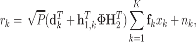 |
(1) |
where P is the transmission power at the BS, Φ = diag{v} is the phase shift matrix at the RIS,  satisfies θn ∈ [0, 2π],
  is the precoding vector to user k, xk is the signal sent to user k and nk is the additive complex Gaussian noise. In addition to the direct link,
  , which is of poor quality, the RIS provides a controllable supplementary link
  . The power of
  can be significantly enhanced by properly adjusting Φ, which can be realized when CSI is available.
In the context of CSI acquisition, this article starts from an introduction of the current categories of RISs, including passive RISs, hybrid RISs and active RISs. Based on the type of CSI to be acquired, implicit and explicit CSI acquisition methods are summarized, respectively. For explicit CSI especially, the methods to separate the direct link and the RIS link channels are first reviewed, involving high-overhead linear cascaded channel estimation in the RIS link. The channel features that can help reduce the cascaded channel estimation overhead are then articulated. Afterwards, the methods to estimate individual channels in the RIS link for different categories of RISs are reviewed. Then, the widely used channel estimation algorithms for explicit CSI acquisition are summarized. Finally, we present two open problems that will arise with the occurrence of new architectures and application scenarios.
Notation.—Letters in normal, lowercase bold and uppercase bold fonts are used for scalars, vectors and matrices, respectively. The superscripts ( · )T, ( · )H and ( · )† return the transpose, conjugate transpose, and pseudo-inverse, respectively; | · | and ‖ · ‖ return the absolute value and the modulus, respectively;  denotes taking the expectation. The notation ⌈ · ⌉ represents rounding up the value; [ · ]m, :, [ · ]:, n and [ · ]m, n extract the mth row, the nth column and the (m, n)th entry of a matrix, respectively. Finally, ‘
 ’ returns the column-wise Kronecker product.
CATEGORIES OF RISs
During the last few years, a variety of RISs have appeared, each with its unique structure and functionalities. In this section, we introduce the existing categories of RISs and make a comparison among them. It should be clarified that the definitions of passive, hybrid and active RISs in this article are determined on the basis of existing RISs that have been published in the literature. With the emergence of new RIS architectures, the definitions and categories of RISs will vary.
Passive RIS
We say that a RIS is passive when it is equipped with neither a power amplifier (PA), low noise amplifier nor signal transmission or reception radio-frequency (RF) chains. Here, passive does not mean that no input power is required by the RIS. A low-level external voltage is still needed to control the phase shift for signal reflection.
The most widely used passive RIS is the reflective-only passive RIS shown in Fig. 2(a) [9–17]. It is usually located on the roof or facade of a building, reflecting signals in front of it. Thus, the reflective-only passive RIS is also named the intelligent reflecting surface (IRS) [11,12]. When an IRS is introduced to assist the mobile communication, the individual channels H2 and h1, k are cascaded together through Φ. The effective channel at the IRS link is H2Φh1, k. Since signal processing modules are absent at the IRS, we can only estimate the channels at the BS or user side.
Figure 2.

Different categories of RISs, including the (a) passive RIS, (b) selection-type hybrid RIS, (c) beamforming-type hybrid RIS and (d) active RIS.
Apart from IRS, some passive RISs have the ability to refract the incident signal, including the refractive-only passive RISs and the simultaneous refractive and reflective passive RISs. A refractive-only passive RIS is also known as a reconfigurable refraction surface (RRS) [18,19]. It is generally located at the BS, acting as a phased antenna array. A RRS refracts the signal transmitted from the feed at the BS and controls the refraction direction of the signal by adjusting its phase. Different from the IRS-assisted system, where the IRS provides an additional link apart from the direct link, in a RRS-assisted system, only the BS-RRS-user link exists.
A passive RIS offering both refraction and reflection [20–22] is referred to as an intelligent omni-direction surface (IOS) or a simultaneously transmitting and reflecting RIS. In an ideal scenario, an IOS can replace window glass to enable signal reflection in front of the window and signal refraction across the window. Then, two users that are at different sides of the IOS can be served at the same time. Channel estimation in RRS and IOS-assisted systems is still in its infancy, and is thus beyond the scope of this review paper.
Hybrid RIS
To address the challenge of channel estimation in passive RIS-assisted mobile systems caused by the absence of signal processing capabilities, a semi-passive RIS, also known as a hybrid active and passive RIS, has been proposed in [23–28]. In this paper, we use a hybrid RIS for the simplification of expression. Hybrid RISs are equipped with signal reception or even transmitting RF chains, which can be connected with active sensors.
Each active sensor has two modes, including the antenna mode and the reflection mode. In the antenna mode, active sensors can receive pilots sent from the BS and users or even transmit pilots to them. Thus, channel estimation is supported at the RIS side. Denote by ρn ∈ [0, 1] the power ratio of the received signal over the incident signal on the nth unit; ρn = 0 and 1 represent the scenarios of the incident signal being completely reflected and received, respectively. When 0 < ρn < 1, signal reflection and reception happen simultaneously. The practical value range of ρn is determined by the hardware structure of the hybrid RIS.
In a hybrid RIS, a few or even all passive RIS units can be replaced by active sensors. Assume that Na out of N units are selected and replaced by active sensors, and that the number of signal reception RF chains is NRF. Generally, we have NRF ≤ Na ≤ N. Thus, a hybrid RIS can perform channel estimation and also maintains the RIS’s advantages of low hardware cost and low power consumption.
Based on the connection type between RF chains and active sensors, we further divide hybrid RISs into two sub-categories. One is the selection-type hybrid RIS, in which at one time instance, each RF chain is connected with only one active sensor, as shown in Fig. 2(b). If NRF < Na then a switch is further needed to make a selection between a RF chain and its possibly connected active sensor. The other is the beamforming-type hybrid RIS, in which each RF chain is connected with multiple or even all active sensors simultaneously. Analog beamforming is performed before signals received by the active sensors are combined at the RF chains, as illustrated in Fig. 2(c).
Active RIS
Figure 2(d) illustrates an active RIS, whose units are all active. Note that an active unit is different from an active sensor. An active unit has only one mode, i.e. the reflection mode. No RF chain is connected with an active unit. It should be connected with a PA to enhance the incident signal power [29–32]. The motivation to introduce active RISs is to overcome the multiplicative pathloss in the BS-RIS and RIS-user channels. However, an active RIS still works solely in the reflection mode and it is not equipped with signal reception RF chains. It cannot transmit or receive signals, and thus does not support channel estimation at the RIS side. Channel estimation in an active RIS-assisted system is the same as that in an IRS-assisted system.
No matter which structure the RIS has, in the data transmission stage, the RIS is switched to the reflection and/or refraction mode and improves the mobile communication quality by adjusting the signal phase. RIS phase shifting operates like analog beamforming in millimeter wave hybrid beamforming systems. In order to optimize the phase shift, acquisition of implicit or explicit CSI at the RIS is indispensable.
IMPLICIT CSI ACQUISITION
If the design of the RIS phase shift in the data transmission stage does not rely on the explicit CSI, i.e. the full channel h1, k or H2 or their cascaded version, then we can simply acquire the implicit CSI. Implicit CSI reflects the channel condition. It can be a beam index, a discrete phase index, etc.
Beam training
The original motivation to introduce RISs is to enhance the total channel power. Recalling Equation (1), the optimal  , or, equivalently, the optimal
  , should maximize
  . Following the beam training approach in hybrid beamforming systems, a predefined RIS phase shift codebook can be utilized, and the optimal RIS beam can be selected after beam sweeping [33–37].
To be specific, define  as the codebook for
  , where
  is the number of RIS beams and
  is the
  th RIS beam. Take the uplink as an example. Within the channel coherence time, the pilot model corresponding to the
  th RIS beam can be expressed as
 |
(2) |
where  is the pilot matrix received by the BS antennas, K is number of users as well as the length of the pilot sequence, Pk is the transmit power of user k,
  is the pilot sequence from user k, satisfying ‖sk‖2 = 1 and
  for k ≠ j and
  is the complex Gaussian noise matrix with independent and identically distributed entries. By multiplying Equation (2) with sk, we can extract the pilot component from user k as
 |
(3) |
The optimal RIS beam for user k with index  is the one that maximizes the pilot reception power:
 |
(4) |
Then,  is selected as the RIS phase shift vector for user k in the data transmission phase and
  is the implicit CSI we need to acquire.
Beam training is an efficient way to find a proper RIS phase shift design that can enhance the total channel quality. The computational complexity of beam training is  , much lower than that of explicit CSI estimation. Most importantly, we do not need to separate the direct link channel and the RIS link channel, and this method is not sensitive to the hardware impairments, such as imperfect phase shift and uncontrollable amplitude variations. However, the performance of beam training relies heavily on the codebook. On the one hand, a fine codebook that can seamlessly cover the whole service region of RIS is extremely powerful. On the other hand, the codebook that satisfies this requirement usually has a large size
  , resulting in a high beam training overhead of
  for K users.
The RIS codebook contains information of the spatial directions. If the user is equipped with multiple antennas as well, and only the line-of-sight (LoS) component exists in the RIS link, then the position of the user can be found with the beam training result [38,39].
Blind beamforming
Apart from a beam index, when the RIS phase shift has limited resolution, a discrete phase shift index can be the implicit CSI we aim to acquire [40–42]. Denote the number of quantization bits of each RIS unit as B. A total of 2B discrete phase shift values, denoted  , can be constructed. When h1, k and H2 are unknown to the RIS, a blind beamforming method is proposed to determine θ1, …, θN in Equation (1) from
  one by one. Similar to beam training above, a set of
  RIS beams, also denoted by
  here, is predefined. The difference is that random beams are utilized here, which means that during the beam sweeping phase, θ1, …, θN are independently and randomly generated from
  . If
. If  is large then, for the nth RIS unit,
  are selected averagely. Take the selection of θn as an example. There are nearly
  beams whose nth entry is
  , similar to
  . Collect all the RIS beams whose nth entry is
  and calculate the average pilot reception power at the BS as
 |
(5) |
Search for  that achieves the highest pilot reception power at the BS:
 |
(6) |
Then, the discrete phase index  is chosen as the phase shift profile of the nth RIS unit. This is the conditional sample mean–based blind beamforming proposed in [41].
The blind beamforming method has an even lower requirement on the codebook, because a randomly generated codebook is acceptable. Similar to beam training, blind beamforming requires a training overhead of  , and is not sensitive to hardware impairments. Its computational complexity is
  , and is thus higher than that of beam training. Blind beamforming has been experimentally verified to work well when N and B are small [41,42]. However, in order to guarantee that a proper
  can be selected for θn, the number of generated random samples or the size of the codebook should still be large. With the user’s movement, blind beamforming may return outdated results, and the whole blind beamforming procedure should run again. Therefore, this method also suffers from the burden of high training overhead.
Implicit CSI acquisition is applicable to all categories of RISs. However, among them, IRS and active RIS-assisted mobile systems are more preferable to acquire implicit CSI since they are not required to have signal reception or processing capabilities. Furthermore, implicit CSI acquisition does not rely heavily on the RIS hardware characteristics. When the RIS has low cost and the hardware impairments cannot be ignored, it is preferable to directly search for a proper RIS phase shift design without estimating the explicit CSI.
DOUBLE LINK CHANNEL SEPARATION
With the development of RIS manufacturing technology, the latest RISs have greatly improved hardware profile, resulting in the enhancement of explicit CSI acquisition robustness. Therefore, more attention has been paid to the estimation of explicit CSI, which refers to h1, k, H2 and their cascaded version. However, pilots in the direct link and in the RIS link are combined together at the receiver, making it difficult to discriminate them. In this section, we focus on the separation of channels in the two links. Commonly used RISs have been verified to offer reciprocity between uplink and downlink channels in TDD systems through experiments [43]. Considering that uplink training requires less pilot overhead than downlink training, we focus on the uplink when we study double link channel separation and the following channel estimation methods.
ON/OFF RIS
An ON/OFF RIS is capable of reflecting and absorbing the incident wave, corresponding to the ON and OFF states, respectively [44,45]. When all RIS units are turned OFF, signals arriving at the RIS will be absorbed instead of being reflected, and, equivalently, we have Φ = 0. The RIS link pilot component is completely diminished, solely resulting in the direct link pilot component in yk. Under this condition, dk can be easily obtained.
Afterwards, by turning ON the RIS units one by one, we can sequentially estimate the channel on each RIS unit. Alternatively, by turning ON all RIS units but alternating the phase shift, the channel on all RIS units can be obtained simultaneously. Based on the fact that
 |
(7) |
the RIS phase shift vector v can be separated from the channel H2diag(h1, k). We define
 |
(8) |
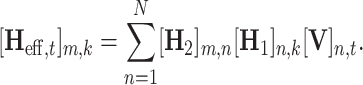
as the cascaded channel, satisfying  . Notably, the expression of H2diag(h1, k) requires that the user is equipped with only one antenna; otherwise, each user antenna corresponds to a distinct cascaded channel. When solely turning ON the nth RIS unit, we can estimate the cascaded channel on this unit, i.e. [Gk]:, n. Owing to Equation (7), the RIS phase shift amount v has been separated from Hk. Thus, with the estimate of Gk, a proper v for data transmission can be designed.
The ON/OFF channel separation method requires N + 1 sets of RIS phase shift configurations. Note that a low-cost RIS usually has a large size, resulting in a large N. Furthermore, when K users exist, the total overhead, involving the length of pilot sequence sk as well, should be K(N + 1). In other words, a long training period is required.
ON-only RIS
When the absorption state is not supported by the RIS, i.e. the RIS only has the ON state, the RIS link pilot component always exists in yk. In order to separate the channels in the two links, special RIS phase shift designs should be applied [46–50]. In the training phase, assume that the tth RIS phase shift vector is  . Then, by rewriting Equation (3), we get the uplink received pilot model from user k corresponding to vt as
 |
(9) |
Since the RIS phase shift vector vt has been separated from Gk and can be known at the BS, we regard vt as the pilot signal too. By stacking the pilot signals over T RIS phase shift vectors together into a matrix, we obtain
 |
(10) |
where  .
.
Given Equation (10), we have two approaches to separate dk and Gk. One is to mathematically turn OFF the direct link. We now seek to find a matrix V that satisfies
 |
(11) |
Then, Gk can be obtained by calculating YkV†. The other approach is to directly estimate the channels in the two links. Define
 |
Then,  can be estimated through the widely used linear channel estimation methods, including least-square (LS) and linear minimum mean square error (LMMSE) schemes, if
  has full rank. A typical instance of
  that can be used in both approaches is an (N + 1)-dimensional discrete Fourier transformation (DFT) matrix, whose entries in the first row are all one. However, T = N + 1 is still required, indicating that the same amount of training overhead as using ON/OFF RIS is required. The computational complexity when
  is a DFT matrix is
  .
.
The double link channel separation methods illustrated above are applicable to all RISs, especially IRSs and active RISs, but are not necessary to hybrid RISs. This is because a hybrid RIS has the ability to estimate the RIS-link channel and then separate the channels into two links with a greatly reduced pilot overhead, which is discussed in the subsequent section entitled ‘Individual channel estimation’.
CASCADED CHANNEL ESTIMATION OVERHEAD REDUCTION
Because of the huge training overhead resulting from the linear estimation of the large-dimensional channel Gk, we need to seek channel features for overhead reduction. Since dk and Gk have already been separated, in this section, we only exploit the channel features in the RIS link that can help reduce the overhead for estimating the cascaded channel Gk.
Scaling law
According to the definition of Gk in Equation (8), for two distinct users k and j, we have
 |
(12) |
The scaling law between Gk and Gj can be found as follows [44,51,52]:
 |
(13) |
That is, given Gj, Gk can be obtained with the N-dimensional scaling channel  . This is because Gk and Gj share the common BS-RIS channel H2. Recalling Equation (9) and omitting the direct link component, we have
 |
(14) |
Then,  can be linearly estimated given yk, Gj and the known vt. By exploiting the scaling law, the cascaded channel of the principle user G1 can be first estimated with the pilot overhead of N. Afterwards, the cascaded channels of other users Gk are obtained by simply estimating
  . Notably, in practical systems, we usually have M < N, causing a rank-deficient pseudo-inversion of Gj. Under this condition, according to [44], a total of ⌈(K − 1)N/M⌉ instead of (K − 1)N pilots are needed to obtain
  . Therefore, the total pilot overhead of multiuser double link channel estimation is greatly reduced from K(N + 1) to N + K + ⌈(K − 1)N/M⌉. The computational complexity is
  .
.
Channel sparsity
When the mobile system works in high frequencies, such as in the millimeter wave or even terahertz frequency bands, the channel experiences significant sparsity if the number of BS antennas or that of the RIS units grows large. Each individual channel is composed of a limited number of propagation paths, and each path can be described using a small amount of spatial parameters. Take the uniform linear array (ULA) as an example. Suppose that the RIS units are arranged in an ULA, and so are the BS antennas. When user k is in the far field of the RIS, h1, k can be expressed as [53]
 |
(15) |
where L1, k is the number of paths in h1, k, satisfying L1, k ≪ N, αl, k is the complex path gain of the lth path, φl, k is the angle of arrival (AoA) of the lth path at RIS, while
 |
(16) |
is the steering vector of an N-element ULA, d is the distance between two adjacent ULA elements and λ is the carrier wavelength. Similarly, in the far-field condition, H2 can be modeled as
 |
(17) |
where L2 is the number of paths in H2, satisfying L2 ≪ {M, N}, βl is the complex path gain of the lth path, ψl is the AoA of the lth path at the BS and ϕl is the AoD of the lth path at the RIS. By applying Equations (15) and (17) in Equation (8), the cascaded channel has the structure
 |
(18) |
Define  , where UM and UN are M- and N-dimensional DFT matrices. Given that L1, kL2 ≪ MN,
  is a sparse matrix with only a few entries having non-vanishing amplitude. Ignoring the direct link component, Equation (10) can be rewritten as
 |
(19) |
By regarding  as a measurement matrix, the sparse channel matrix
  can be estimated through compressed sensing or deep learning, which requires greatly reduced training overhead [23,51,54,55]. Alternatively, given the structured channel model in Equation (18), Gk can be reconstructed using the spatial parameters, including
  ,
,  and
and  [56–62]. Then, the channel reconstruction problem is translated to a parameter estimation problem, which also requires only a small amount of training overhead. Denote the average sparsity of
  , as
, as  , satisfying
  . The total overhead approximates
  , and the computational complexity is generally
  .
.
Furthermore, because the L1, kL2 paths in Gk are stemming from L1, k + L2 practical paths in h1, k and H2, the multiuser cascaded channels  , hold common row sparsity[51]. Figure 3 illustrates the modulo of cascaded channel matrices of two users, i.e.
  and
and  . The biggest proportion of power of
  is captured by the same rows that capture the major proportion of power of
  , demonstrating the common row sparsity between
  and
and  . The common sparsity and the channel scaling both result from the common channel H2. Exploring the common sparsity among multiple users can further reduce the pilot overhead and the computational complexity.
Figure 3.

Common row sparsity between cascaded channels of (a) user 1 and (b) user 2. Red boxes frame the LoS paths in two channels.
The cascaded channel is usually estimated in IRS and active RIS-assisted mobile systems. Nevertheless, for a hybrid RIS, since individual channels can be estimated, it is not necessary to estimate the cascaded channel.
INDIVIDUAL CHANNEL ESTIMATION
Under some special channel conditions in an IRS or active RIS-assisted system, as well as in a hybrid RIS-assisted system, the individual channels H2 and h1, k can be separated.
IRS and active RIS
Since the IRS and the active RIS do not have signal processing capabilities, whilst the channel estimation can be performed only at the BS or user side, it is not easy to obtain the individual channels or separate them from the cascaded one. To be specific, recalling the scaling law in Equation (12), we may take H2diag(h1, j) and  to be H2 and h1, j, respectively, causing severe estimation errors. Moreover, from the multipath cascaded channel model in Equation (18), we see that the spatial angles that can be estimated by the BS are
  and
and  . The AoA at the BS
  can be clearly distinguished. The AoA and AoD at the RIS are added together, forming
  . We cannot separate
  and
and  from their superposition without any prior information. Therefore, it is not easy to separate H2 and h1, k from Gk.
However, if partial CSI is known in advance then it becomes possible to correctly separate H2 and h1, k. A LoS path usually exists between the BS and the RIS to guarantee a good performance of the latter. Recalling the channel model of H2 in Equation (17), let the first path be the LoS path. The LoS path has the strongest power, satisfying |β1| ≥ |βl| for l > 1. The expression of β1 can be further derived from the free-space propagation path loss model [63]. The angles of the LoS path, i.e. ψ1 and θ1, are determined by the locations of the BS and the RIS and known in advance when the BS and the RIS are fixed [58,64,65]. Recall the example in Fig. 3. If sin ψ1 and sin θ1 are fixed then  can be determined from
  for l1 = 1, …, L1, k. Moreover, given β1, it is easy to derive
  from
from  . That is, all the spatial parameters in h1, k have been successfully obtained, and h1, k can be reconstructed by applying
  , in Equation (15). Then, H2 can be extracted from H2diag(h1, k) given h1, k. Following the parameter estimation approach, in this condition, the total pilot overhead of estimating the double link channels approximates
  , where
  is the average sparsity of h1, k, k = 1, …, K, satisfying
  . Hence, the computational complexity is about
  .
.
Another way to separate the individual channels in the RIS link is to perform the parallel factor (PARAFAC) decomposition [66,67], which belongs to multiway analysis. By stacking h1, k, k = 1, …, K, together into a matrix, we have  . Given vt, the effective channel is defined as
 |
(20) |
where
 |
(21) |
A three-way matrix  can be formulated, which has the following forms:
 |
(22) |
 |
(23) |
Given a random initial value, H2 and H1 can be iteratively and alternatively estimated from  and
and  , respectively, through the linear estimation algorithms, such as LS. However, the PARAFAC decomposition-based individual channel separation method requires min(M, K) ≥ N, which is hard to achieve in practice. According to [66], the training overhead is in the range of [K + 2, K + N], and the computational complexity is
  .
.
Selection-type hybrid RIS
Hybrid RISs can make individual channel estimation easier to implement. For the selection-type hybrid RIS, we denote the channel between user k and the Na active sensors and the channel between user k and the N − Na passive units as  and
and  , respectively. When active sensors choose the antenna mode, the signal received by the active sensors from user k can be expressed as
 |
(24) |
Given ya, 1, k, we can directly estimate ha, 1, k. However, if the active sensors are fixed and satisfy Na ≪ N then hp, 1, k can be obtained only through extrapolation from ha, 1, k, which requires that the hp, 1, k are correlated with the ha, 1, k. When h1, k satisfies the model in Equation (15), ha, 1, k and hp, 1, k share the same set of spatial parameters αl, k, sin φl, k, l = 1, …, L1, k, and, thus, are highly correlated [23,25,68]. By applying these parameters in Equation (15), the full channel h1, k is reconstructed. Alternatively, exploring the sparse structure or directly employing neural networks, h1, k can be obtained from ha, 1, k as well. The training overhead of acquiring h1, k is K.
Similarly, H2 can be reconstructed by the BS sending downlink pilots to the RIS. If the active sensors are further equipped with signal transmission RF chains then H2 can also be reconstructed by the RIS sending uplink pilots to the BS. Notably, pilot sequences from different BS antennas or RIS active sensors should be orthogonal to each other, causing a training overhead of M or Na. The second way to obtain H2 is to conduct estimation at the BS. Having estimated the cascaded channel Gk, H2 can be acquired given h1, k. However, the estimation of Gk needs a training overhead of  , because the RIS should alter the phase shift profile. Take the estimation of both-side individual channels at the RIS as an instance. The total pilot overhead of acquiring H2, h1, k and dk for k = 1, …, K is 2K + M, and the computational complexity is
  .
.
Beamforming-type hybrid RIS
For the beamforming-type hybrid RIS architecture, each RIS unit has the opportunity to be connected with a RF chain. Therefore, it is possible to make full channel estimation instead of channel extrapolation. However, since NRF ≪ N, an analog beam sweeping stage is required, similar to hybrid beamforming systems [27,28]. We still take the estimation of h1, k as an example. At time instance t, when the uplink pilot from user k arrives at the RIS, we have
 |
(25) |
where  is the received pilot across the NRF RF chains,
  contains NRF RIS reception beams,
  is the RIS reception beam in the mth RF chain in time instance t,
  if the nth RIS unit is connected with the mth RF chain, where ρn, t ∈ [0, 1] is the power ratio of the received signal over the incident signal and ϑm, n, t ∈ [0, 2π] is the reception phase shift, and [wm, t]n = 0 otherwise. After collecting pilots in ⌈N/NRF⌉ time instances, the N-dimensional channel h1, k can be linearly estimated. If h1, k is sparse and satisfies the multipath model in Equation (15) then the training overhead can be further reduced through compressed sensing or parameter estimation methods.
Channel H2 can be obtained at the RIS by using downlink pilots sent from the BS in similar approaches, and the pilot sequences from different BS antennas should be orthogonal to each other. Alternatively, we can also utilize the uplink pilot components reflected by the RIS and received by the BS, which in time instance t is mathematically expressed as
 |
(26) |
where the nth entry of the reflection phase shift vector  satisfies
  . Then, H2 can be estimated following the same approaches as that for the selection-type hybrid RISs. Similarly, take the linear estimation of both-side individual channels at RIS as an example, and suppose that Wt is in the DFT format. The total pilot overhead of acquiring H2, h1, k and dk for k = 1, …, K is K[1 + (1 + M)⌈N/NRF⌉], and the computational complexity is
  .
.
Double time scales
In a typical RIS-assisted mobile communication system, the locations of the BS and the RIS are fixed. The BS is generally mounted at the top of a building, and the RIS is then deployed in the LoS region of the BS to guarantee a strong link between them. The environment between the BS and the RIS is relatively stable, and thus the coherence time of H2, denoted as T2, is long. On the other hand, the mobile user has a high probability to keep moving. The coherence time of h1, k, denoted T1, k, is much shorter than T2. Therefore, channel estimation can be performed in double time scales [69–71]. For longer T2, the estimation of H2 only needs to be performed once. Within this period, the estimation of h1, k is performed in every shorter period of T1, k. Since the training overhead required by the estimation of h1, k is limited when H2 is given, the overall overhead of double time scale training can be very low.
CHANNEL ESTIMATION ALGORITHMS
A comprehensive comparison of the overhead and complexity of the above mentioned existing CSI acquisition methods is provided in Table 1. Moreover, Table 2 summarizes the applicability of these methods to different categories of RISs.
Table 1.
Overhead and complexity of existing CSI acquisition methods for acquiring H2, h1, k, and dk, k = 1, …, K.
| CSI acquisition method | Overhead | Complexity | |
|---|---|---|---|
| Implicit CSI acquisition | Beam training |

|

|
| Blind beamforming |

|

|
|
| Double link channel separation | ON/OFF RIS | K(N + 1) |

|
| ON-only RIS | K(N + 1) |

|
|
| Cascaded channel estimation | Scaling law |

|

|
| Channel sparsity |

|

|
|
| Individual channel estimation | IRS/active RIS (LoS) |

|

|
| Selection type | 2K + M |

|
|
| Beamforming type |

|

|
|
Table 2.
Applicability of existing CSI acquisition methods to different categories of RISs.
| Hyrbid RIS | |||
|---|---|---|---|
| CSI acquisition method | IRS/active RIS | Selection type | Beamforming type |
| Implicit CSI acquisition | Preferable | Not necessary | Not necessary |
| Double link channel separation | Preferable | Not necessary | Not necessary |
| Cascaded channel estimation | Preferable | Not necessary | Not necessary |
| Individual channel estimation | Conditional | Preferable | Preferable |
In previous sections, we briefly mentioned the algorithms that are used to estimate the channels or their parameters, including linear estimation, compressed sensing, parameter estimation and deep learning. This section will provide more details about them in the context of RIS-assisted mobile communication systems.
Linear estimation
Linear estimation is the most classic and widely used estimation method in practical systems [72]. The computational complexity is fixed and the estimation accuracy is stable. Linear estimation methods do not rely on channel features or structures like Equation (15) or (17). Referring back to Equation (10), which has the expression
 |
(27) |
the LS estimate of  is
is
 |
(28) |
and the LMMSE estimate is
 |
(29) |
where  is the covariance matrix of the channel
  and
and  is the variance of the noise. Notably,
  should have full column rank, which requires a sufficient amount of pilot overhead [28]. Considering that LMMSE has much higher estimation accuracy than LS, it is more widely adopted for channel estimation in RIS-assisted systems [44,73,74].
Compressed sensing
When the channels are sparse, compressed sensing can be applied for low-overhead channel estimation. Recall the signal model for compressed sensing-based cascaded channel estimation in Equation (19) such that  is the sparse cascaded channel in the angular domain to be estimated. We say that
  is in the angular domain because
  is built on the dictionaries UM and UN, which simultaneously and uniformly sample and draw grids on the angles. Each entry of
  represents the channel component on the corresponding sampled angular pair on the two-dimensional (2D) grid. Given Equation (19), the general problem to be solved by compressed sensing can be written as
 |
(30) |
where ε is a predefined residual threshold. The problem requires using the smallest amount of entries in  to capture the majority of information in the channel. Sparse channel representations and compressed sensing problems for hybrid RISs in Equations (24) and (25) can be expressed in a similar way.
Since the sparsity, i.e. the number of distinct entries in  , is unknown in advance, and in order to avoid the huge computational complexity caused by exhaustive search, a typical solution is the greedy algorithm such as orthogonal match pursuit (OMP) [23,75,76]. By inspecting the problem in Equation (30), other algorithms such as the alternating direction method of multipliers [25,27,77] can also recover the sparse channel.
In a multiuser scenario, the scaling law as well as the common sparsity between Gk and Gj can be exploited in compressed sensing-based channel estimation [51,75,76]. By writing Gj as
 |
(31) |
we see that users share a common sparse base  , which can be recovered through the multiple measurement vector-based compressed sensing estimator for accuracy enhancement.
Super-resolution parameter estimation
Unlike compressed sensing, which describes the angles using a grid defined by the dictionary, super-resolution parameter estimation aims to obtain more precise angular estimates that are no longer limited by the grids. We still take the cascaded channel as an example. Let Gk = Gk(Θk), where  contains the angles to be estimated. We now rewrite Equation (10), by ignoring the direct link, as
 |
(32) |
We seek to estimate Θk from  . For example, maximum likelihood (ML) estimation finds the angles that satisfy [56,57]
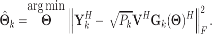 |
(33) |
Apart from ML, classic and widely used super-resolution parameter estimation algorithms include multiple signal classification, estimation of signal parameters via rotational invariance techniques, etc. [78–80]. Even though these algorithms have different objective functions, a super-resolution grid is generally required. This grid can be much denser than the grid in compressed sensing methods. By searching over the grid, one grid point that can satisfy the objective function is chosen as the estimate.
If the grid density is not high then a further step is conducted to refine the on-grid estimate towards the one that is closer to the real angle value. Under this condition, enhancement of the parameter estimation accuracy can be achieved on basis of the on-grid estimates obtained by compressed sensing. For example, a gradient descent step can be added after the grid-based matching in each iteration of OMP [59,61]. Alternatively, a Newton refinement step can also refine the on-grid angle estimates towards their real values [58]. Newton refinement integrated with OMP forms the Newtonized orthogonal matching pursuit algorithm [81], which has been widely applied in sparse channel reconstruction [82–84]. Another compressed sensing-based approach, which can overcome the on-grid effect, is atomic norm minimization [39,60,68,85], where the grid is composed of infinite cardinality.
Acquisition of the spatial parameters not only supports low-overhead sparse channel reconstruction, but enables further applications such as user or target localization [38,39,56,57].
Deep learning
Deep learning has experienced rapid development in recent years. When applied to channel estimation, deep learning does not heavily rely on a precise channel model like Equation (15), (17) or (18). In RIS-assisted systems, deep learning can be used to estimate the cascaded channel or the individual channels for both the IRS and hybrid RIS.
In an IRS-assisted system, deep learning is usually adopted to estimate the cascaded channel Gk. By directly regarding the received pilots at the BS or user side as the input of the neural network, the estimate of Gk can serve as the output of a convolutional neural network [86,87]. Alternatively, deep learning can be introduced to further enhance the accuracy of LS or LMMSE cascaded channel estimation results. By regarding it as a denoising problem, a deep residual network can be applied to fix this problem [88,89]. The denoising concept was also applied in [90]. Different from Liu et al. [88,89], Jin et al. [90] regarded the channel matrix as an image. Three practical residual neural networks were adopted to improve the cascaded channel estimation accuracy, while the network input was the received pilot matrix.
Deep learning-based channel estimation is also preferable in hybrid RIS-assisted systems. For the selection-type hybrid RIS especially, since pilots can be received by a small amount of active units, only the sampled channel on these units can be directly estimated. Then, the full channel can be extrapolated through a residual network. The input of the network is the sampled channel, and the output is the full channel [24]. The denoising approach can be further applied here. Considering that the accuracy of the full channel reconstruction from a few observations on the active sensors is limited, a denoising neural network can be employed to refine the channel reconstruction result [55].
OPEN PROBLEMS
From the review above, we see that extensive research has been carried out on CSI acquisition in traditional RIS-assisted mobile communication scenarios. In future mobile systems, the emergence of new architectures and new application scenarios of RISs entails new challenges. In this section, we discuss two open problems that have to be addressed in the context of CSI acquisition in future RIS-assisted systems.
Near-field effect
A RIS has the attractive advantages of low cost and low power consumption. Thus, we can increase the size of a RIS to further improve wireless communication services. However, as the RIS grows large, the user or the BS falls into the near field of the large RIS. Then, the near-field effect kicks in [64,91–94]. Under this condition, in the multipath channel model, each path is described by the 2D or 3D position of the user, BS or scatterer, instead of their direction or angle as in the far-field channel. The near-field steering vector  is different from the far-field one, whose nth entry can be expressed as
 |
(34) |
where (r, θ) is the polar position of the user, BS or scatterer, and Dn(rl, θl) is the distance between the user, BS or scatterer and the nth RIS unit. Take h1, k as an example. The near-field channel h1, k can be modeled as
 |
(35) |
Note that the sparsity of a near-field channel is not always apparent under the DFT transformation. When the user is quite close to the RIS, a large angular spread can be observed even if only a single LoS path exists in h1, k. Compressed sensing and super-resolution parameter estimation should be adjusted to cater for the near-field effect. In particular, the channel parameters to be estimated become (rl, θl), l = 1, …, L1, k. Moreover, by exploring these parameters, user localization can be achieved if the LoS path exists.
High-mobility scenarios
High-mobility wireless communications, including high-speed trains and unmanned aerial vehicles (UAVs) scenarios, have gained increasing attention over the past years. For the purpose of enhancing the coverage and providing seamless wireless services with low cost, the introduction of RISs have been considered in these high-mobility systems [95–98]. However, since trains and UAVs move fast, the environment and the channel vary rapidly. Wireless communication in high-mobility scenarios suffers from a severe Doppler effect and the channel aging problem [98]. In IRS-assisted systems especially, channel estimation in the RIS link becomes even more challenging. Hence, how to efficiently obtain CSI with limited pilot overhead is of great importance.
Fortunately, the property of double time scales can also be exploited in high-mobility scenarios. Take the high-speed train scenario as an example. The RIS can be deployed on one side of the railway, coated on the window of the train, or on the wall or roof of the train [95,99]. If the location of the RIS is fixed then H2 varies slowly and has a much longer channel coherence time than h1, k and dk. On the other hand, if the RIS moves with a high-speed train then the coherence time of h1, k becomes longer than that of H2 and dk, which is different from the double time scales in the formal case. Equally important, temporal correlation exists among channels in continuous time slots [98]. CSI obtained in previous time slots can be utilized to track the fast-varying channel in time with reduced pilot overhead. Furthermore, the Doppler effect can be mitigated by leveraging the time–frequency space framework [100]. However, the fast handover in high-mobility scenarios is an issue that cannot be ignored, introducing challenges to CSI acquisition in RIS-assisted systems.
CONCLUSIONS
This article provided a comprehensive review of the state of the art on CSI acquisition in RIS-assisted mobile communication systems. Newly appeared categories of RISs, including selection-type and beamforming-type hybrid RISs as well as active RISs, were considered. By classifying CSI into implicit CSI and explicit CSI, we surveyed the acquisition of these two types of CSI. Acquisition of explicit CSI was studied via a step-by-step approach, from double link channel separation, low-overhead cascaded channel estimation, individual channel estimation to the estimation algorithms. The review ended with two open problems in future RIS-assisted systems. We articulated that, with the emergence of more advanced RISs and algorithms, CSI acquisition in RIS-assisted mobile systems will experience new breakthroughs.
Contributor Information
Yu Han, National Mobile Communications Research Laboratory, Southeast University, Nanjing 210096, China.
Wankai Tang, National Mobile Communications Research Laboratory, Southeast University, Nanjing 210096, China.
Xiao Li, National Mobile Communications Research Laboratory, Southeast University, Nanjing 210096, China.
Michail Matthaiou, Centre for Wireless Innovation (CWI), Queen’s University Belfast, Belfast BT3 9DT, UK.
Shi Jin, National Mobile Communications Research Laboratory, Southeast University, Nanjing 210096, China.
FUNDING
This work was supported in part by the National Natural Science Foundation of China (62261160576, 61921004, 62231009, 61971126, 62201138 and 62341107), the Natural Science Foundation of Jiangsu Province (BK20211511 and BK20220809), the Jiangsu Province Frontier Leading Technology Basic Research Project (BK20212002) and the joint project of China Mobile Research Institute and Southeast University. The work of M.M. was supported by a research grant from the Department for the Economy Northern Ireland under the US-Ireland R&D Partnership Programme.
Conflict of interest statement. None declared.
REFERENCES
- 1. Cui TJ, Qi MQ, Wan Xet al. Coding metamaterials, digital metamaterials and programmable metamaterials. Light Sci Appl 2014; 3: e218. 10.1038/lsa.2014.99 [DOI] [Google Scholar]
- 2. Li L Jun Cui T, Ji Wet al. Electromagnetic reprogrammable coding-metasurface holograms. Nat Commun 2017; 8: 197. 10.1038/s41467-017-00164-9 [DOI] [PMC free article] [PubMed] [Google Scholar]
- 3. Zhang L, Chen XQ, Liu Set al. Space-time-coding digital metasurfaces. Nat Commun 2018; 9: 4334. 10.1038/s41467-018-06802-0 [DOI] [PMC free article] [PubMed] [Google Scholar]
- 4. Ma Q, Bai GD, Jing HBet al. Smart metasurface with self-adaptively reprogrammable functions. Light Sci Appl 2019; 8: 98. 10.1038/s41377-019-0205-3 [DOI] [PMC free article] [PubMed] [Google Scholar]
- 5. Hu J, Zhang H, Di Bet al. Reconfigurable intelligent surface based rf sensing: design, optimization, and implementation. IEEE J Sel Areas Commun 2020; 38: 2700–16. 10.1109/JSAC.2020.3007041 [DOI] [Google Scholar]
- 6. Zhang H, Zhang H, Di Bet al. Metalocalization: reconfigurable intelligent surface aided multi-user wireless indoor localization. IEEE Trans Wirel Commun 2021; 20: 7743–57. 10.1109/TWC.2021.3087354 [DOI] [Google Scholar]
- 7. Alexandropoulos GC, Shlezinger N, Del Hougne P. Reconfigurable intelligent surfaces for rich scattering wireless communications: recent experiments, challenges, and opportunities. IEEE Commun Mag 2021; 59: 28–34. 10.1109/MCOM.001.2001117 [DOI] [Google Scholar]
- 8. Nguyen CL, Georgiou O, Gradoni Get al. Wireless fingerprinting localization in smart environments using reconfigurable intelligent surfaces. IEEE Access 2021; 9: 135526–41. 10.1109/ACCESS.2021.3115596 [DOI] [Google Scholar]
- 9. Huang C, Alexandropoulos GC, Zappone Aet al. Energy efficient multi-user MISO communication using low resolution large intelligent surfaces. In: 2018 IEEE Globecom Workshops (GC Wkshps), Abu Dhabi, United Arab Emirates. New York: IEEE Press, 2018, 1–6. [Google Scholar]
- 10. Huang C, Zappone A, Alexandropoulos GCet al. Reconfigurable intelligent surfaces for energy efficiency in wireless communication. IEEE Trans Wirel Commun 2019; 18: 4157–70. 10.1109/TWC.2019.2922609 [DOI] [Google Scholar]
- 11. Wu Q, Zhang R. Intelligent reflecting surface enhanced wireless network: joint active and passive beamforming design. In: 2018 IEEE Global Communications Conference (GLOBECOM), Abu Dhabi, United Arab Emirates. New York: IEEE Press, 2018, 1–6. [Google Scholar]
- 12. Wu Q, Zhang R. Intelligent reflecting surface enhanced wireless network via joint active and passive beamforming. IEEE Trans Wirel Commun 2019; 18: 5394–409. 10.1109/TWC.2019.2936025 [DOI] [Google Scholar]
- 13. Han Y, Tang W, Jin Set al. Large intelligent surface-assisted wireless communication exploiting statistical CSI. IEEE Trans Veh Technol 2019; 68: 8238–42. 10.1109/TVT.2019.2923997 [DOI] [Google Scholar]
- 14. Basar E Di Renzo M, De Rosny Jet al. Wireless communications through reconfigurable intelligent surfaces. IEEE Access 2019; 7: 116753–73. 10.1109/ACCESS.2019.2935192 [DOI] [Google Scholar]
- 15. Di Renzo M, Zappone A, Debbah Met al. Smart radio environments empowered by reconfigurable intelligent surfaces: how it works, state of research, and the road ahead. IEEE J Sel Areas Commun 2020; 38: 2450–525. 10.1109/JSAC.2020.3007211 [DOI] [Google Scholar]
- 16. Tang W, Chen MZ, Chen Xet al. Wireless communications with reconfigurable intelligent surface: path loss modeling and experimental measurement. IEEE Trans Wirel Commun 2020; 20: 421–39. 10.1109/TWC.2020.3024887 [DOI] [Google Scholar]
- 17. Chen W, Wen CK, Li Xet al. Channel customization for limited feedback in RIS-assisted FDD systems. IEEE Trans Wirel Commun 2022; doi: 10.1109/TWC.2022.3226442. 10.1109/TWC.2022.3226442 [DOI] [Google Scholar]
- 18. Zeng S, Zhang H, Di Bet al. Reconfigurable refractive surfaces: an energy-efficient way to holographic MIMO. IEEE Commun Lett 2022; 26: 2490–4. 10.1109/LCOMM.2022.3189980 [DOI] [Google Scholar]
- 19. Zeng S, Zhang H, Di Bet al. Multi-user holographic MIMO systems: reconfigurable refractive surface or phased array? In: 2018 IEEE Global Communications Conference (GLOBECOM), Rio de Janeiro, Brazil. New York: IEEE Press, 2022, 645–50. 10.1109/LCOMM.2022.3189980 [DOI] [Google Scholar]
- 20. Zeng S, Zhang H, Di Bet al. Reconfigurable intelligent surfaces in 6G: reflective, transmissive, or both? IEEE Commun Lett 2021; 25: 2063–7. 10.1109/LCOMM.2021.3062615 [DOI] [Google Scholar]
- 21. Zhang H, Di B. Intelligent omni-surfaces: simultaneous refraction and reflection for full-dimensional wireless communications. IEEE Commun Surv Tutor 2022; 24: 1997–2028. 10.1109/COMST.2022.3202813 [DOI] [Google Scholar]
- 22. Mu X, Liu Y, Guo Let al. Simultaneously transmitting and reflecting (STAR) RIS aided wireless communications. IEEE Trans Wirel Commun 2021; 21: 3083–98. 10.1109/TWC.2021.3118225 [DOI] [Google Scholar]
- 23. Taha A, Alrabeiah M, Alkhateeb A. Enabling large intelligent surfaces with compressive sensing and deep learning. IEEE Access 2021; 9: 44304–21. 10.1109/ACCESS.2021.3064073 [DOI] [Google Scholar]
- 24. Jin Y, Zhang J, Zhang Xet al. Channel estimation for semi-passive reconfigurable intelligent surfaces with enhanced deep residual networks. IEEE Trans Veh Technol 2021; 70: 11083–8. 10.1109/TVT.2021.3109937 [DOI] [Google Scholar]
- 25. Hu J, Yin H, Björnson E. MmWave MIMO communication with semi-passive RIS: a low-complexity channel estimation scheme. In: 2021 IEEE Global Communications Conference (GLOBECOM), Madrid, Spain. New York,: IEEE Press, 2021, 1–6. [Google Scholar]
- 26. Li M, Zhang S, Ge Yet al. Joint channel estimation and data detection for hybrid RIS aided millimeter wave OTFS systems. IEEE Trans Commun 2022; 70: 6832–48. 10.1109/TCOMM.2022.3199019 [DOI] [Google Scholar]
- 27. Alexandropoulos GC, Vlachos E. A hardware architecture for reconfigurable intelligent surfaces with minimal active elements for explicit channel estimation. In: 2020 IEEE International Conference on Acoustics, Speech and Signal Processing (ICASSP), Barcelona, Spain. New York: IEEE Press, 2020, 9175–9. [Google Scholar]
- 28. Zhang H, Shlezinger N, Alamzadeh Iet al. Channel estimation with simultaneous reflecting and sensing reconfigurable intelligent metasurfaces. In: 2021 IEEE 22nd International Workshop on Signal Processing Advances in Wireless Communications (SPAWC), Lucca, Italy. New York: IEEE Press, 2021, 536–40. [Google Scholar]
- 29. Long R, Liang YC, Pei Yet al. Active reconfigurable intelligent surface-aided wireless communications. IEEE Trans Wirel Commun 2021; 20: 4962–75. 10.1109/TWC.2021.3064024 [DOI] [Google Scholar]
- 30. Zhang Z, Dai L, Chen Xet al. Active RIS vs. passive RIS: which will prevail in 6G? IEEE Trans Commun 2023; 71: 1707–25. 10.1109/TCOMM.2022.3231893 [DOI] [Google Scholar]
- 31. You C, Zhang R. Wireless communication aided by intelligent reflecting surface: active or passive? IEEE Wirel Commun Lett 2021; 10: 2659–63. 10.1109/LWC.2021.3111044 [DOI] [Google Scholar]
- 32. Zhi K, Pan C, Ren Het al. Active RIS versus passive RIS: which is superior with the same power budget? IEEE Commun Lett 2022; 26: 1150–4. 10.1109/LCOMM.2022.3159525 [DOI] [Google Scholar]
- 33. You C, Zheng B, Zhang R. Fast beam training for irs-assisted multiuser communications. IEEE Wirel Commun Lett 2020; 9: 1845–9. 10.1109/LWC.2020.3005980 [DOI] [Google Scholar]
- 34. Pei X, Yin H, Tan Let al. Ris-aided wireless communications: prototyping, adaptive beamforming, and indoor/outdoor field trials. IEEE Trans Commun 2021; 69: 8627–40. 10.1109/TCOMM.2021.3116151 [DOI] [Google Scholar]
- 35. Huang H, Wang X, Zhang Cet al. Reward-maximization-based passive beamforming for multi-RIS-aided multi-user MISO systems. In: 2021 IEEE Global Communications Conference (GLOBECOM), Madrid, Spain. New York: IEEE Press, 2021, 1–6. [Google Scholar]
- 36. Ning B, Chen Z, Chen Wet al. Terahertz multi-user massive MIMO with intelligent reflecting surface: beam training and hybrid beamforming. IEEE Trans Veh Technol 2021; 70: 1376–93. 10.1109/TVT.2021.3052074 [DOI] [Google Scholar]
- 37. Ma X, Chen Z, Huang Cet al. Cooperative beam training for reconfigurable intelligent surface enabled terahertz MIMO networks via multi-task learning, arXiv: 2207.02597v2
- 38. He J, Wymeersch H, Sanguanpuak Tet al. Adaptive beamforming design for mmwave RIS-aided joint localization and communication. In: 2020 IEEE Wireless Communications and Networking Conference Workshops (WCNCW), Seoul, Korea (South). Piscataway, NJ: IEEE Press, 2020, 1–6. 10.1109/WCNCW48565.2020.9124848 [DOI] [Google Scholar]
- 39. He J, Wymeersch H, Juntti M. Leveraging location information for RIS-aided mmWave MIMO communications. IEEE Wirel Commun Lett 2021; 10: 1380–4. 10.1109/LWC.2021.3067474 [DOI] [Google Scholar]
- 40. Zhang Y, Ren S, Shen Ket al. Optimal discrete beamforming for intelligent reflecting surface. In: 2021 IEEE Global Communications Conference (GLOBECOM), Madrid, Spain. New York: IEEE Press, 2021, 1–6. [Google Scholar]
- 41. Ren S, Shen K, Zhang Yet al. Configuring intelligent reflecting surface with performance guarantees: blind beamforming. IEEE Trans Wirel Commun 2022; 22: 3355–70. 10.1109/TWC.2022.3217679 [DOI] [Google Scholar]
- 42. Li J, Gao B, Yu Zet al. Coverage enhancement of 5G commercial network based on reconfigurable intelligent surface. In: 2022 IEEE 96th Vehicular Technology Conference (VTC2022-Fall), London, UK. New York: IEEE Press, 2022, 1–5. [Google Scholar]
- 43. Tang W, Chen X, Chen MZet al. On channel reciprocity in reconfigurable intelligent surface assisted wireless networks. IEEE Wirel Commun 2021; 28: 94–101. 10.1109/MWC.001.2100136 [DOI] [Google Scholar]
- 44. Wang Z, Liu L, Cui S. Channel estimation for intelligent reflecting surface assisted multiuser communications: framework, algorithms, and analysis. IEEE Trans Wirel Commun 2020; 19: 6607–20. 10.1109/TWC.2020.3004330 [DOI] [Google Scholar]
- 45. Yang Y, Zheng B, Zhang Set al. Intelligent reflecting surface meets OFDM: protocol design and rate maximization. IEEE Trans Commun 2020; 68: 4522–35. 10.1109/TCOMM.2020.2981458 [DOI] [Google Scholar]
- 46. Zheng B, Zhang R. Intelligent reflecting surface-enhanced OFDM: channel estimation and reflection optimization. IEEE Wirel Commun Lett 2019; 9: 518–22. 10.1109/LWC.2019.2961357 [DOI] [Google Scholar]
- 47. Jensen TL, De Carvalho E. An optimal channel estimation scheme for intelligent reflecting surfaces based on a minimum variance unbiased estimator. In: 2020 IEEE International Conference on Acoustics, Speech and Signal Processing (ICASSP), Barcelona, Spain. New York: IEEE Press, 2020, 5000–4. [Google Scholar]
- 48. Swindlehurst AL, Zhou G, Liu Ret al. Channel estimation with reconfigurable intelligent surfaces–a general framework. Proc IEEE 2022; 110: 1312–38. 10.1109/JPROC.2022.3170358 [DOI] [Google Scholar]
- 49. Pan C, Zhou G, Zhi Ket al. An overview of signal processing techniques for RIS/IRS-aided wireless systems. IEEE J Sel Topics Signal Process 2022; 16: 883–917. 10.1109/JSTSP.2022.3195671 [DOI] [Google Scholar]
- 50. Alwazani H, Kammoun A, Chaaban Aet al. Intelligent reflecting surface-assisted multi-user MISO communication: channel estimation and beamforming design. IEEE Open J Commun Soc 2020; 1: 661–80. 10.1109/OJCOMS.2020.2992791 [DOI] [Google Scholar]
- 51. Chen J, Liang YC, Cheng HVet al. Channel estimation for reconfigurable intelligent surface aided multi-user mmWave MIMO systems, IEEE Trans Wirel Commun 2023; doi: 10.1109/TWC.2023.3246264.
- 52. Zheng B, You C, Zhang R. Intelligent reflecting surface assisted multi-user OFDMA: channel estimation and training design. IEEE Trans Wirel Commun 2020; 19: 8315–29. 10.1109/TWC.2020.3021434 [DOI] [Google Scholar]
- 53. Sayeed AM. Deconstructing multiantenna fading channels. IEEE Trans Signal Process 2002; 50: 2563–79. 10.1109/TSP.2002.803324 [DOI] [Google Scholar]
- 54. Wang P, Fang J, Duan Het al. Compressed channel estimation for intelligent reflecting surface-assisted millimeter wave systems. IEEE Signal Process Lett 2020; 27: 905–9. 10.1109/LSP.2020.2998357 [DOI] [Google Scholar]
- 55. Liu S, Gao Z, Zhang Jet al. Deep denoising neural network assisted compressive channel estimation for mmWave intelligent reflecting surfaces. IEEE Trans Veh Technol 2020; 69: 9223–8. 10.1109/TVT.2020.3005402 [DOI] [Google Scholar]
- 56. Fascista A, Coluccia A, Wymeersch Het al. RIS-aided joint localization and synchronization with a single-antenna mmwave receiver. In: 2021 IEEE International Conference on Acoustics, Speech and Signal Processing (ICASSP), Toronto, ON, Canada. New York: IEEE Press, 2021, 4455–9. [Google Scholar]
- 57. Fascista A, Keskin MF, Coluccia Aet al. RIS-aided joint localization and synchronization with a single-antenna receiver: beamforming design and low-complexity estimation. IEEE J Sel Topics Signal Process 2022; 16: 1141–56. 10.1109/JSTSP.2022.3177925 [DOI] [Google Scholar]
- 58. Liu Y, Zhang S, Gao Fet al. Cascaded channel estimation for RIS assisted mmWave MIMO transmissions. IEEE Wirel Commun Lett 2021; 10: 2065–9. 10.1109/LWC.2021.3092147 [DOI] [Google Scholar]
- 59. He J, Leinonen M, Wymeersch Het al. Channel estimation for RIS-aided mmWave MIMO channels. In: 2020 IEEE Global Communications Conference (GLOBECOM). New York: IEEE Press, 2020, 1–6.
- 60. He J, Wymeersch H, Juntti M. Channel estimation for RIS-aided mmWave MIMO systems via atomic norm minimization. IEEE Trans Wirel Commun 2021; 20: 5786–97. 10.1109/TWC.2021.3070064 [DOI] [Google Scholar]
- 61. Zhou Z, Cai B, Chen Jet al. Dictionary learning-based channel estimation for RIS-aided MISO communications. IEEE Wirel Commun Lett 2022; 11: 2125–9. 10.1109/LWC.2022.3194585 [DOI] [Google Scholar]
- 62. Schroeder R, He J, Juntti M. Passive RIS vs. hybrid RIS: A comparative study on channel estimation. In: 2021 IEEE 93rd Vehicular Technology Conference (VTC2021-Spring), Helsinki, Finland. New York: IEEE Press, 2021, 1–7. [Google Scholar]
- 63. ITU-R . Calculation of free-space attenuation. Technical report P.525–4, International Telecommunications Union - Radiocommunications Sector (ITU-R), 2019. [Google Scholar]
- 64. Han Y, Jin S, Wen CKet al. Localization and channel reconstruction for extra large RIS-assisted massive MIMO systems. IEEE J Sel Topics Signal Process 2022; 16: 1011–25. 10.1109/JSTSP.2022.3174654 [DOI] [Google Scholar]
- 65. Ling T, Han Y, Jin Set al. Two-phase parameter-based separate channel estimation in RIS-Aided MIMO OFDM systems. In: 2023 IEEE International Conference on Communications (ICC), Rome, Italy. New York: IEEE Press, 2023. [Google Scholar]
- 66. Wei L, Huang C, Alexandropoulos GCet al. Channel estimation for RIS-empowered multi-user MISO wireless communications. IEEE Trans Commun 2021; 69: 4144–57. 10.1109/TCOMM.2021.3063236 [DOI] [Google Scholar]
- 67. Wei L, Huang C, Alexandropoulos GCet al. Parallel factor decomposition channel estimation IN ris-assisted multi-user MISO communication. In: 2020 IEEE 11th Sensor Array and Multichannel Signal Processing Workshop (SAM), Hangzhou, China. New York: IEEE Press, 2020, 1–5. [Google Scholar]
- 68. Schroeder R, He J, Brante Get al. Two-stage channel estimation for hybrid RIS assisted MIMO systems. IEEE Trans Commun 2022; 70: 4793–806. 10.1109/TCOMM.2022.3176654 [DOI] [Google Scholar]
- 69. Hu C, Dai L, Han Set al. Two-timescale channel estimation for reconfigurable intelligent surface aided wireless communications. IEEE Trans Commun 2021; 69: 7736–47. 10.1109/TCOMM.2021.3072729 [DOI] [Google Scholar]
- 70. Wei X, Shen D, Dai L. Channel estimation for RIS assisted wireless communications–part I: fundamentals, solutions, and future opportunities. IEEE Commun Lett 2021; 25: 1398–402. 10.1109/LCOMM.2021.3052822 [DOI] [Google Scholar]
- 71. Guo J, Chen W, Wen CKet al. Deep learning-based two-timescale CSI feedback for beamforming design in RIS-assisted communications. IEEE Trans Veh Technol 2023; 72: 5452–7. 10.1109/TVT.2022.3226220 [DOI] [Google Scholar]
- 72. Van De Beek JJ, Edfors O, Sandell Met al. On channel estimation in OFDM systems. In: 1995 IEEE 45th Vehicular Technology Conference, Chicago, IL, USA. New York: IEEE Press, 1995, 815–9. [Google Scholar]
- 73. Demir ÖT, Björnson E. Is channel estimation necessary to select phase-shifts for RIS-assisted massive MIMO? IEEE Trans Wirel Commun 2022; 21: 9537–52. 10.1109/TWC.2022.3177700 [DOI] [Google Scholar]
- 74. Zhi K, Pan C, Ren Het al. Reconfigurable intelligent surface-aided MISO systems with statistical CSI: Channel estimation, analysis and optimization. In: 2021 IEEE 22nd International Workshop on Signal Processing Advances in Wireless Communications (SPAWC), Lucca, Italy. New York: IEEE Press, 2021, 576–80. 10.1109/SPAWC51858.2021.9593154 [DOI] [Google Scholar]
- 75. Wei X, Shen D, Dai L. Channel estimation for RIS assisted wireless communications–part II: an improved solution based on double-structured sparsity. IEEE Commun Lett 2021; 25: 1403–7. 10.1109/LCOMM.2021.3052787 [DOI] [Google Scholar]
- 76. Abdallah A, Celik A, Mansour MMet al. RIS-aided mmwave MIMO channel estimation using deep learning and compressive sensing. IEEE Trans Wirel Commun 2023; 22: 3503–21. [Google Scholar]
- 77. Liu H, Zhang J, Wu Qet al. ADMM based channel estimation for RISs aided millimeter wave communications. IEEE Commun Lett 2021; 25: 2894–8. 10.1109/LCOMM.2021.3095218 [DOI] [Google Scholar]
- 78. Deepak B, Sankar R, Chepuri SP. Channel estimation for RIS-assisted millimeter-wave MIMO systems. arXiv: 2011.00900v2.
- 79. Hu X, Zhang R, Zhong C. Semi-passive elements assisted channel estimation for intelligent reflecting surface-aided communications. IEEE Trans Wirel Commun 2021; 21: 1132–42. 10.1109/TWC.2021.3102446 [DOI] [Google Scholar]
- 80. Hu X, Liu C, Peng Met al. IRS-based integrated location sensing and communication for mmWave SIMO systems. IEEE Trans Wirel Commun 2022; doi: 10.1109/TWC.2022.3223428. 10.1109/TWC.2022.3223428 [DOI] [Google Scholar]
- 81. Mamandipoor B, Ramasamy D, Madhow U. Newtonized orthogonal matching pursuit: frequency estimation over the continuum. IEEE Trans Signal Process 2016; 64: 5066–81. 10.1109/TSP.2016.2580523 [DOI] [Google Scholar]
- 82. Han Y, Hsu TH, Wen CKet al. Efficient downlink channel reconstruction for FDD multi-antenna systems. IEEE Trans Wirel Commun 2019; 18: 3161–76. 10.1109/TWC.2019.2911497 [DOI] [Google Scholar]
- 83. Han Y, Liu Q, Wen CKet al. FDD massive MIMO based on efficient downlink channel reconstruction. IEEE Trans Commun 2019; 67: 4020–34. 10.1109/TCOMM.2019.2900625 [DOI] [Google Scholar]
- 84. Garg N, Sellathurai M, Ratnarajah T. Low complexity joint OMP methods for FDD channel estimation in massive MIMO systems. In: 2020 IEEE 21st International Workshop on Signal Processing Advances in Wireless Communications (SPAWC), Atlanta, GA, USA. New York: IEEE Press, 2020, 1–5. [Google Scholar]
- 85. Chung H, Kim S. Location-aware channel estimation for RIS-aided mmWave MIMO systems via atomic norm minimization. arXiv: 2107.09222v1.
- 86. Elbir AM, Papazafeiropoulos A, Kourtessis Pet al. Deep channel learning for large intelligent surfaces aided mm-wave massive MIMO systems. IEEE Wirel Commun Lett 2020; 9: 1447–51. 10.1109/LWC.2020.2993699 [DOI] [Google Scholar]
- 87. Shen W, Qin Z, Nallanathan A. Deep learning enabled channel estimation for RIS-aided wireless systems. In: 2022 IEEE Global Communications Conference (GLOBECOM), Rio de Janeiro, Brazil. New York: IEEE Press, 2022, 4226–31. [Google Scholar]
- 88. Liu C, Liu X, Ng DWKet al. Deep residual network empowered channel estimation for IRS-assisted multi-user communication systems. In: IEEE International Conference on Communications (ICC), Montreal, QC, Canada. New York: IEEE Press, 2021, 1–7. [Google Scholar]
- 89. Liu C, Liu X, Ng DWKet al. Deep residual learning for channel estimation in intelligent reflecting surface-assisted multi-user communications. IEEE Trans Wirel Commun 2021; 21: 898–912. 10.1109/TWC.2021.3100148 [DOI] [Google Scholar]
- 90. Jin Y, Zhang J, Huang Cet al. Multiple residual dense networks for reconfigurable intelligent surfaces cascaded channel estimation. IEEE Trans Veh Technol 2022; 71: 2134–9. 10.1109/TVT.2021.3132305 [DOI] [Google Scholar]
- 91. Rahal M, Denis B, Keykhosravi Ket al. RIS-enabled localization continuity under near-field conditions. In: 2021 IEEE 22nd International Workshop on Signal Processing Advances in Wireless Communications (SPAWC), Lucca, Italy. New York: IEEE Press, 2021, 436–40. [Google Scholar]
- 92. Abu-Shaban Z, Keykhosravi K, Keskin MFet al. Near-field localization with a reconfigurable intelligent surface acting as lens. In: IEEE International Conference on Communications (ICC), Montreal, QC, Canada. New York: IEEE Press, 2021, 1–6. [Google Scholar]
- 93. Dardari D, Decarli N, Guerra Aet al. LOS/NLOS near-field localization with a large reconfigurable intelligent surface. IEEE Trans Wirel Commun 2021; 21: 4282–94. 10.1109/TWC.2021.3128415 [DOI] [Google Scholar]
- 94. Emenonye DR, Dhillon HS, Buehrer RM. RIS-aided localization under position and orientation offsets in the near and far field. IEEE Trans Wirel Commun 2022; 21: 3083–98. [Google Scholar]
- 95. Zhang J, Liu H, Wu Qet al. RIS-aided next-generation high-speed train communications: challenges, solutions, and future directions. IEEE Wirel Commun 2021; 28: 145–51. 10.1109/MWC.001.2100170 [DOI] [Google Scholar]
- 96. Xu J, Ai B. When mmWave high-speed railway networks meet reconfigurable intelligent surface: a deep reinforcement learning method. IEEE Wirel Commun Lett 2022; 11: 533–7. 10.1109/LWC.2021.3135602 [DOI] [Google Scholar]
- 97. Chen Y, Wang Y, Zhang Jet al. QoS-driven spectrum sharing for reconfigurable intelligent surfaces (RISs) aided vehicular networks. IEEE Trans Wirel Commun 2021; 20: 5969–85. 10.1109/TWC.2021.3071332 [DOI] [Google Scholar]
- 98. Xu C, An J, Bai Tet al. Channel estimation for reconfigurable intelligent surface assisted high-mobility wireless systems. IEEE Trans Veh Technol 2023; 72: 718–34. 10.1109/TVT.2022.3203818 [DOI] [Google Scholar]
- 99. Wang K, Lam CT, Ng BK. How to deploy RIS to minimize delay spread in HST communications: Railroad side, or train side? In: 2022 IEEE 22nd International Conference on Communication Technology (ICCT), Nanjing, China. New York: IEEE Press, 2022, 793–7. 10.1109/ICCT56141.2022.10073344 [DOI] [Google Scholar]
- 100. Xu C, Xiang L, An Jet al. OTFS-aided RIS-assisted SAGIN systems outperform their OFDM counterparts in doubly selective high-Doppler scenarios. IEEE Internet Things J 2023; 10: 682–703. 10.1109/JIOT.2022.3203895 [DOI] [Google Scholar]